
Torque Tube, Torque Converter Bearing Replacement Procedure w/pics
 12-19-2010, 01:10 PM
#1
Rennlist Member
Thread Starter
Join Date: Sep 2007
Location: Ridgecrest, California
Posts: 1,363
Likes: 0
Received 143 Likes
on
28 Posts
CH00 EXECUTIVE SUMMARY
December 2010
In general, this procedure covers removal of the exhaust system, rear suspension, transmission and Torque Tube (TT), servicing the TT bearings (both OEM and Constantine’s Super Bearings), installing bearings and Constantine’s Super Clamp, and then re-installing the transmission, rear suspension and a new X-Pipe exhaust for a 1987 928. However, some background is included to aid others in troubleshooting (the hard way) driveline bearing problems. My story begins with California, my 1984 Daily Driver.
About a year ago, I began to notice a faint “whirring” sound coming from underneath my 1984 Daily Driver while I was half-way across the country on one of my cross-country drives. Initially, I thought it was something serious about to break and leave me stranded on some lonely stretch of Interstate Highway while buzzards circled overhead. However, I decided to press on with my trip. After all, California IS the oldest and most abused 928 in our collection. If something broke, I would just have to deal with it. After I completed that cross country trip without incident and California was still going strong but with a louder “whirring” noise than when I started, I decided to continue driving it locally. About 12,000 miles later, it became so loud it was annoying. It was now growling and changed pitch in perfect unison with engine RPM regardless of whether the car was in gear or not.
After some research on Rennlist, I learned that the noise could be produced by either the TT bearings OR the Torque Converter (TC) bearings. Initially, I could not tell if the noise was coming from the TT or the TC. I just HAD to know for sure which one was causing the noise so decided to replace the TT bearings first and see what happened. I proceeded to remove the rear suspension and transmission on California and replaced the OEM TT bearings with Constantine’s Super Bearings. The OEM TT bearings did seem a bit worn compared to the sound of new bearings (virtually silent) and since I was not experienced enough to judge how worn a bearing would have to be to produce noise, I decided to proceed with replacing the TT bearings only. I put it all back together and viola! The noise was back again! Obviously, it MUST be the TC bearings that were bad!!
So I took it all apart again and replaced the TC bearings and sure enough, one of the TC bearings was noticeably worse than any other bearings. It felt rough when spinning the bearing and was noticeably louder than any of the original bearings. I put everything back together again and this time I experienced Silence! Nothing more than the melodious note of the factory exhaust system – SUCCESS! Today, California is back in service as my Daily Driver. I know, I know – I should have headed the sage advice of the Rennlist community and simply replaced both TT and TC bearings at the same time if I was experiencing drive line bearing failure noises! Some people have to learn things the hard way – I’m one of them!
Having so much fun taking California apart (twice), I decided to move on to Virginia (Wife’s ’87 928 DD). There wasn’t anything wrong with the bearings but I wanted to install a new Super Clamp from Constantine and deal with the slipping drive shaft clamp and potential Thrust Bearing Failure risk once and for all! While I was in there, I decided to replace the OEM TT bearings with Constantine’s Super Bearings as well. It was this latest task of replacing these bearings and installing the Super Clamp on Virginia that I documented the procedure.
WARNING: This procedure is intended to be a Newbie-Rated, STEP-BY-STEP Pictorial guide to removing all the parts necessary to get at the TT bearings, repair the bearings, and re-install everything back to working order. Therefore, it is picture INTENSIVE. There are approximately 580 pictures in this guide.
Finally, I would like to note that there are many ways to perform the work following in this write up. There are many variations to make it easier (and quicker) and I have documented just one. I welcome other thoughts and ideas and experiences to improve the overall quality of this post.
I’ve included a Table of Contents to make it easier to find a section of interest by simply searching for the Chapter Number (e.g., “CH01”). As always, feel free to comment or add ideas that will improve the overall quality of this procedure. ENJOY!
Table of Contents
CH01 Parts-Tools-Preparation
CH02 Removing Exhaust System
CH03 Removing Rear Suspension
CH04 Disconnecting TT from Engine
CH05 Removing Transmission and TT
CH06 Disconnecting TT from Transmission
CH07 Removing TT Bearings
CH08 Removing and Installing TC Bearings
CH09 Servicing TT OEM Bearings
CH10 Servicing TT Super Bearings
CH11 Installing TT Bearings
CH12 Installing Drive Shaft
CH13 Connecting TT to Transmission
CH14 Installing Transmission and TT
CH15 Installing Rear Suspension
CH16 Installing Exhaust System
CH17 Wrap Up
Here we go......
Last edited by Dwayne; 12-20-2010 at 12:38 PM.

The following 2 users liked this post by Dwayne:
jeff spahn (07-10-2019),
Niels_928_s4 (07-11-2023)
12-19-2010, 01:25 PM
#2
Rennlist Member
Thread Starter
Join Date: Sep 2007
Location: Ridgecrest, California
Posts: 1,363
Likes: 0
Received 143 Likes
on
28 Posts
CH01 PARTS-TOOLS-PREPARATION
First, the PARTS. For this Torque Tube Bearing job, I replaced the following parts:
1. Torque Tube Bearings (2 or 3 are needed depending on your application). You may replace with the OEM bearings available through Roger Tyson or you can upgrade to the Super Bearings available from Constantine. This procedure covers servicing both types of bearings as well as installation. Both California�s (1984 Auto) and Virginia�s (1987 Auto) TT contained just 2 OEM bearings. I understand manual transmission TTs contain 3 bearing units. I decided to replace the 2 OEM TT bearings with 3 of Constantine�s Super Bearings in this procedure.
2. Torque Converter Bearings. Two are needed and they are available through Roger Tyson.
3. Constantine�s Super Clamp
4. Automatic Transmission Fluid (7 quarts) � if working on an automatic
Optional parts:
1. Automatic Transmission Fluid Pan Gasket (PET Part #126.271.028.0)
2. Automatic Transmission Fluid Reservoir O-Ring (PET Part #477.321.487)
3. Transmission fluid return line at transmission (PET Part #928.307.039.00)
4. Transmission fluid supply line at transmission replacement rubber hose and clamps (PET Part #928.307.070.00 is NLA)
5. Transmission fluid supply line and return line sealing rings, qty 5 (PET Part #900.123.007.30) 14mm X 18mm
SPECIAL TOOLS
I used a few special tools for this job and they include:
1. Hydraulic Shop Press (for pressing out/in bearings)
2. Large Sockets matched to bearing size for pressing out/in bearings on the shop press
3. 3-Jaw pulley puller
4. 6� Threaded Rod size 5/8�, 11 threads per inch (standard) along with 3 standard nuts and flat washers. I use the threaded rod to remove and install the TT bearings.
5. Approximately 6� of 3 �� ABS Plastic pipe. I used this for helping to install the OEM bearing carriers. If you are using Constantine�s Super Bearings, this is not needed.
6. I used a furniture dolly with a piece of plywood on top as a platform to rest the front of the TT on when removing and installing the transmission/TT assembly.
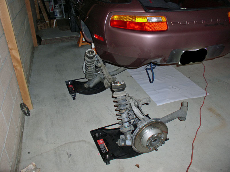
7. I purchased a set of car dollies from Harbor Freight to assist with removing the rear suspension�.
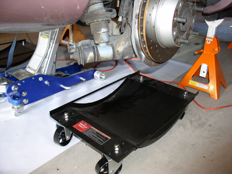
They provide a stable, easy �to-maneuver way to move the rear suspension once it�s removed from the car.
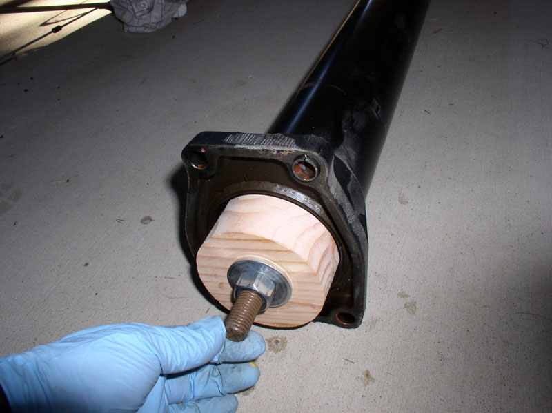
8. I used a pre-cut section of 1 �� X 6� threaded pipe from Home Depot for installing the TC bearings�.
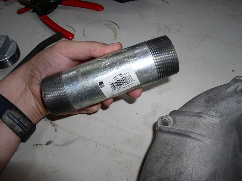
�.I also purchased a threaded cap from Home Depot as pictured below. The cap is threaded on the inside to match the threads on the pipe. This provided a nice flat surface to apply hydraulic press force.
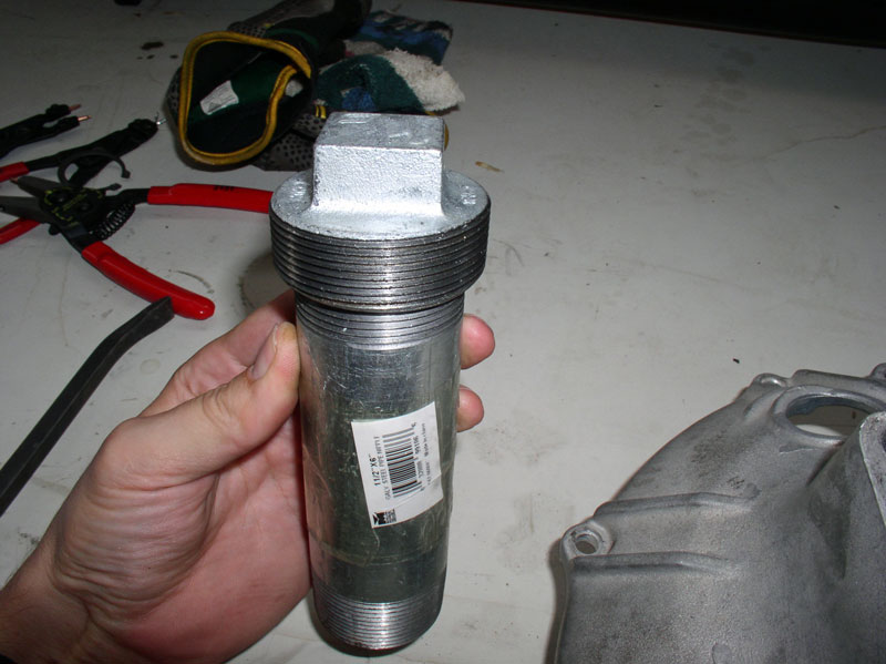
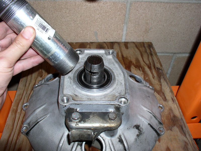
The threaded pipe matches the shoulder of the TC bearing and also allows the TC spline shaft to move inside. This procedure is demonstrated later in CH08 Removing and Installing TC Bearings.
Continued....
First, the PARTS. For this Torque Tube Bearing job, I replaced the following parts:
1. Torque Tube Bearings (2 or 3 are needed depending on your application). You may replace with the OEM bearings available through Roger Tyson or you can upgrade to the Super Bearings available from Constantine. This procedure covers servicing both types of bearings as well as installation. Both California�s (1984 Auto) and Virginia�s (1987 Auto) TT contained just 2 OEM bearings. I understand manual transmission TTs contain 3 bearing units. I decided to replace the 2 OEM TT bearings with 3 of Constantine�s Super Bearings in this procedure.
2. Torque Converter Bearings. Two are needed and they are available through Roger Tyson.
3. Constantine�s Super Clamp
4. Automatic Transmission Fluid (7 quarts) � if working on an automatic
Optional parts:
1. Automatic Transmission Fluid Pan Gasket (PET Part #126.271.028.0)
2. Automatic Transmission Fluid Reservoir O-Ring (PET Part #477.321.487)
3. Transmission fluid return line at transmission (PET Part #928.307.039.00)
4. Transmission fluid supply line at transmission replacement rubber hose and clamps (PET Part #928.307.070.00 is NLA)
5. Transmission fluid supply line and return line sealing rings, qty 5 (PET Part #900.123.007.30) 14mm X 18mm
SPECIAL TOOLS
I used a few special tools for this job and they include:
1. Hydraulic Shop Press (for pressing out/in bearings)
2. Large Sockets matched to bearing size for pressing out/in bearings on the shop press
3. 3-Jaw pulley puller
4. 6� Threaded Rod size 5/8�, 11 threads per inch (standard) along with 3 standard nuts and flat washers. I use the threaded rod to remove and install the TT bearings.
5. Approximately 6� of 3 �� ABS Plastic pipe. I used this for helping to install the OEM bearing carriers. If you are using Constantine�s Super Bearings, this is not needed.
6. I used a furniture dolly with a piece of plywood on top as a platform to rest the front of the TT on when removing and installing the transmission/TT assembly.
7. I purchased a set of car dollies from Harbor Freight to assist with removing the rear suspension�.
They provide a stable, easy �to-maneuver way to move the rear suspension once it�s removed from the car.
8. I used a pre-cut section of 1 �� X 6� threaded pipe from Home Depot for installing the TC bearings�.
�.I also purchased a threaded cap from Home Depot as pictured below. The cap is threaded on the inside to match the threads on the pipe. This provided a nice flat surface to apply hydraulic press force.
The threaded pipe matches the shoulder of the TC bearing and also allows the TC spline shaft to move inside. This procedure is demonstrated later in CH08 Removing and Installing TC Bearings.
Continued....
12-19-2010, 01:28 PM
#4
Archive Gatekeeper
Rennlist Member
Rennlist Member
Early Christmas present from Dwayne! Maybe I'll go buy an automatic so I can play along at home.... 
 12-19-2010, 01:40 PM
#6
Rennlist Member
Thread Starter
Join Date: Sep 2007
Location: Ridgecrest, California
Posts: 1,363
Likes: 0
Received 143 Likes
on
28 Posts
CUSTOM TOOLS
I fabricated two custom tools for this job. The first is a wooden shuttle used in conjunction with the threaded rod to extract the TT bearings and it is also used to install the new TT bearings. I started with a piece of 4� x 6� lumber (a 4� x 4� piece could also be used). I scribed a 3 1/2� diameter circle with a compass. Then I drilled a 1� diameter hole in the center of the circle. Next, I cut out the 3 1/2� diameter circle out of the 4� x 6� lumber stock with a band saw. I then sanded the edges smooth on a table belt sander to make the outer edges perfectly smooth. It should look like this when completed.
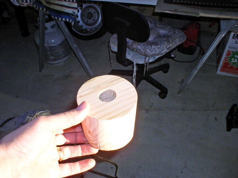
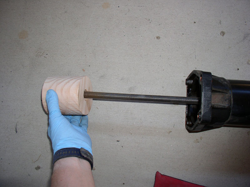
The shuttle is placed on the threaded rod when removing the TT bearings as depicted in the following pictures
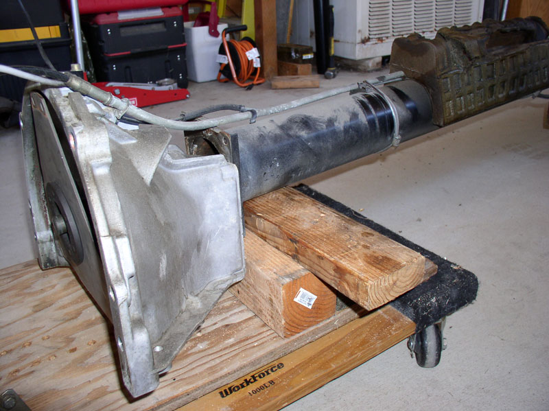
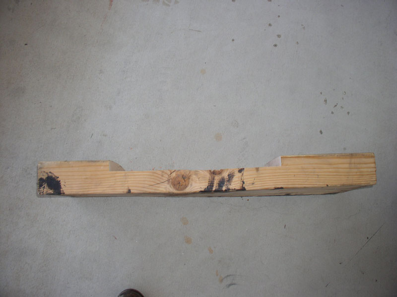
The second tool I fabricated was a transmission platform for supporting the automatic transmission upon removal and installation. I didn�t like the idea of supporting the transmission from underneath the transmission fluid pan as I thought this may distort the pan and may damage the gasket seal. Therefore, I found a scrap piece of 4� x 12� lumber and made a few cuts with the sliding miter saw. If you are interested in making a similar tool, here�s a few of the measurements. The side profile of the platform looks like this:
Overall length is approximately 35 inches. The center cut is offset from the front by approximately 7 inches and from the rear by approximately 11 inches�.
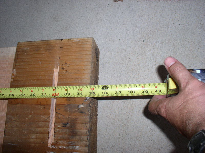
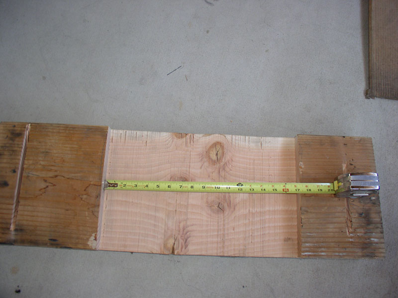
�the length of the center cut is approximately 17���.
�..the depth of the center cut is 1 3/8� inches. I would not make it any less than this depth in order to clear the transmission fluid pan. It could even be 1 �� deep and still work.
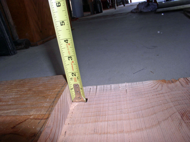
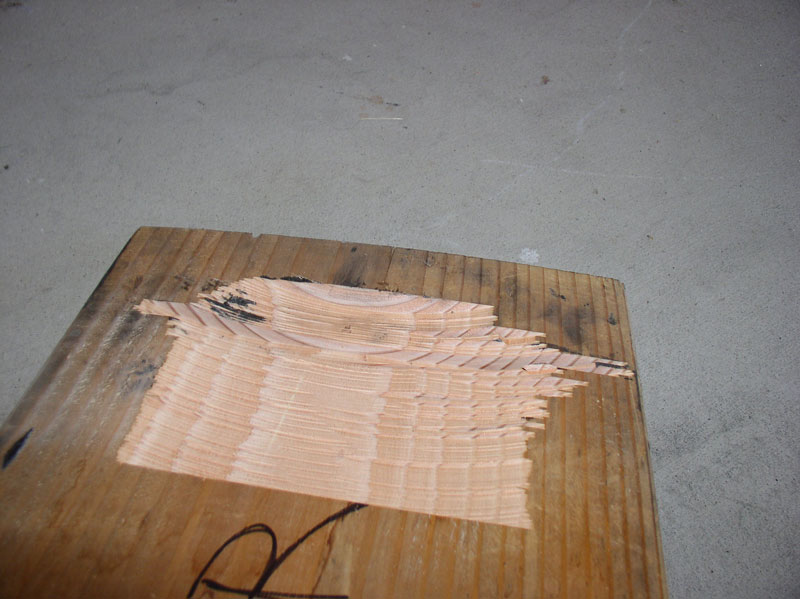
To provide transmission stability while on the platform, I cut concave recesses in both the front and rear of the platform for the torque converter housing and differential housing, respectively to rest in. These were cut with the miter saw (12� blade) by simply bringing the blade down on the wood platform and setting the depth stop on the blade to cut approximately 3/4� deep.
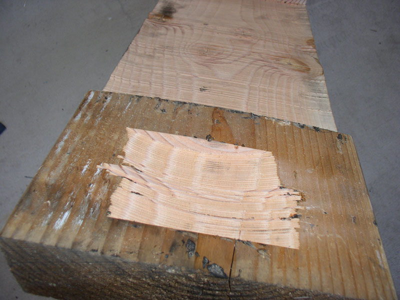
Here�s the rear cut for the differential to rest in.
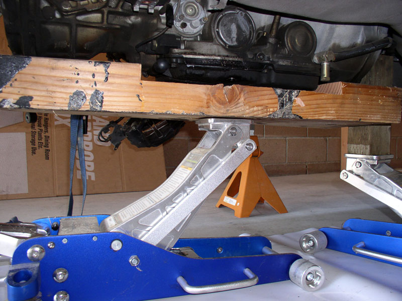
When in operation, it looks like this.
Continued...
I fabricated two custom tools for this job. The first is a wooden shuttle used in conjunction with the threaded rod to extract the TT bearings and it is also used to install the new TT bearings. I started with a piece of 4� x 6� lumber (a 4� x 4� piece could also be used). I scribed a 3 1/2� diameter circle with a compass. Then I drilled a 1� diameter hole in the center of the circle. Next, I cut out the 3 1/2� diameter circle out of the 4� x 6� lumber stock with a band saw. I then sanded the edges smooth on a table belt sander to make the outer edges perfectly smooth. It should look like this when completed.
The shuttle is placed on the threaded rod when removing the TT bearings as depicted in the following pictures
The second tool I fabricated was a transmission platform for supporting the automatic transmission upon removal and installation. I didn�t like the idea of supporting the transmission from underneath the transmission fluid pan as I thought this may distort the pan and may damage the gasket seal. Therefore, I found a scrap piece of 4� x 12� lumber and made a few cuts with the sliding miter saw. If you are interested in making a similar tool, here�s a few of the measurements. The side profile of the platform looks like this:
Overall length is approximately 35 inches. The center cut is offset from the front by approximately 7 inches and from the rear by approximately 11 inches�.
�the length of the center cut is approximately 17���.
�..the depth of the center cut is 1 3/8� inches. I would not make it any less than this depth in order to clear the transmission fluid pan. It could even be 1 �� deep and still work.
To provide transmission stability while on the platform, I cut concave recesses in both the front and rear of the platform for the torque converter housing and differential housing, respectively to rest in. These were cut with the miter saw (12� blade) by simply bringing the blade down on the wood platform and setting the depth stop on the blade to cut approximately 3/4� deep.
Here�s the rear cut for the differential to rest in.
When in operation, it looks like this.
Continued...
12-19-2010, 01:53 PM
#7
Rennlist Member
Thread Starter
Join Date: Sep 2007
Location: Ridgecrest, California
Posts: 1,363
Likes: 0
Received 143 Likes
on
28 Posts
PREPARATION
I took a little detour on this TT bearing replacement job to replace the rear half shaft CV Boots since Virginia�s were split�..
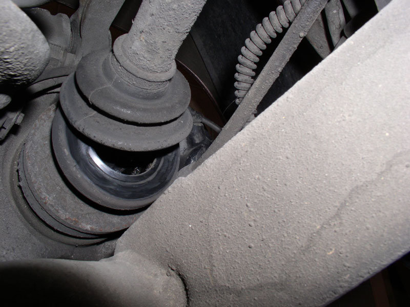
If you have the same issue, you can follow my steps to remove the half shafts. I will not be detailing the CV boot replacement procedure in this write up since I�ve covered that procedure in another write up. Otherwise, if your CV boots are in good shape, simply ignore the steps below that start with �[CV Boot repair prep step]�.
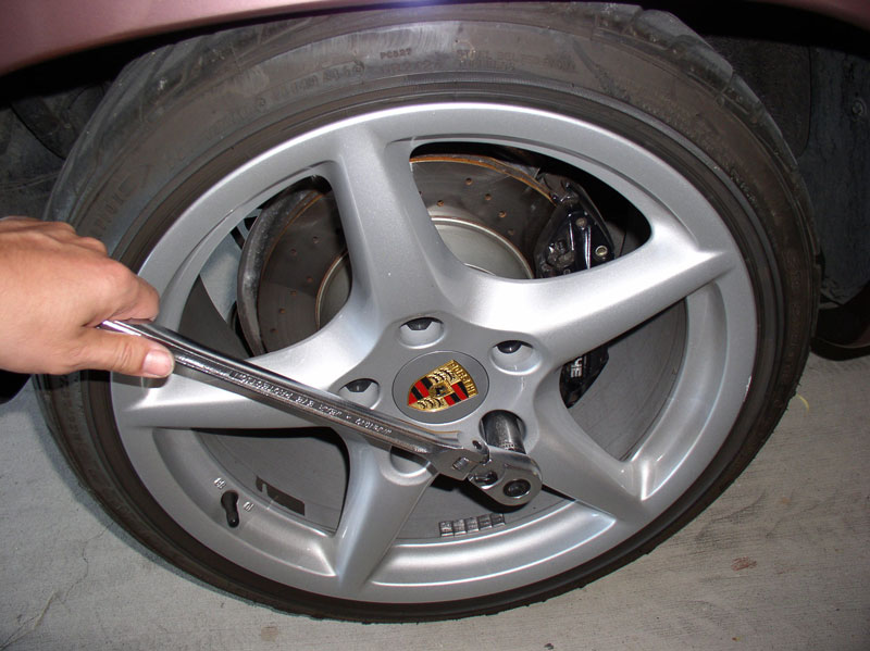
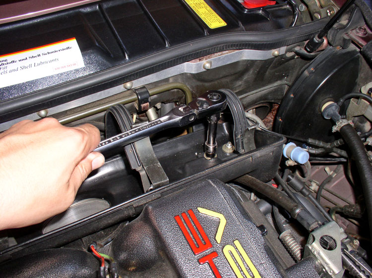
[CV Boot repair prep step] Since I was going to remove the half shafts, I needed to loosen the rear axle nuts while the car was still on the ground. I used a �� drive breaker bar with 32mm impact socket.
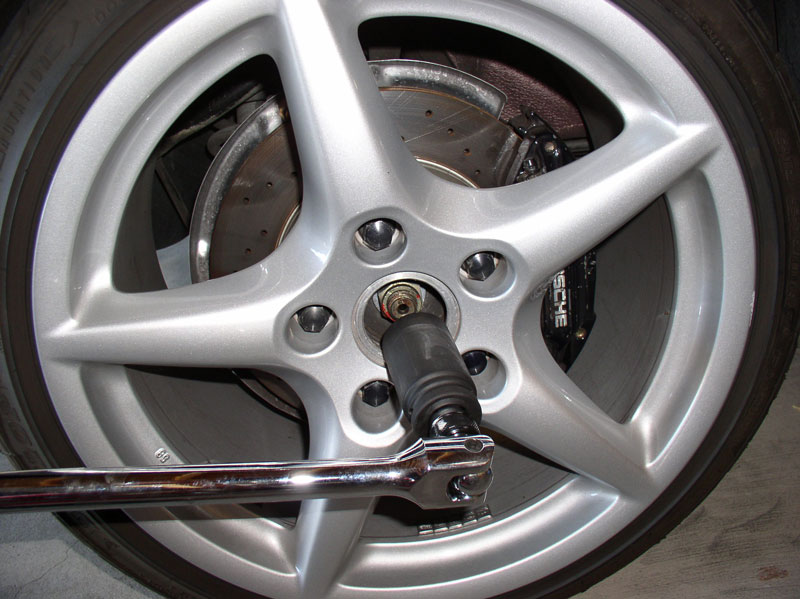
[CV Boot repair prep step] I blocked the tires as well as set the parking brake. Then you can use an extension pipe on the end of the breaker bar as shown�..
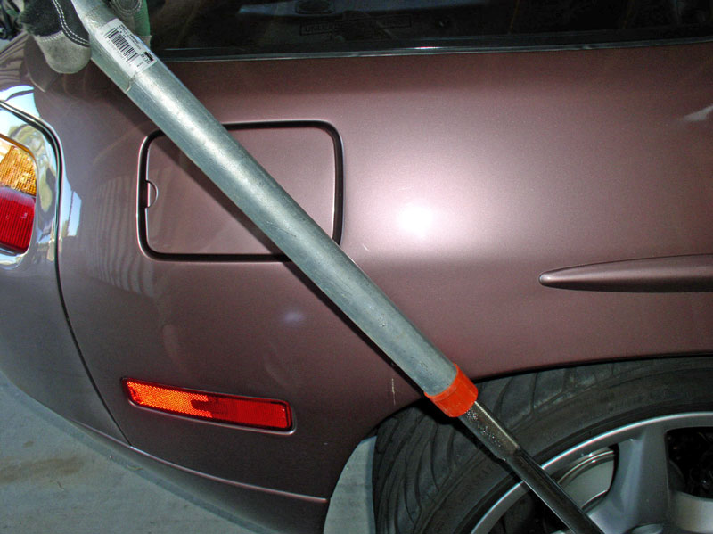
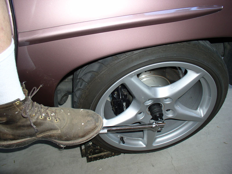
[CV Boot repair prep step] OR you can let gravity assist you if you weigh enough. I weigh about 250 pounds and simply stood on the end of the breaker bar and gave a little �bounce� and the nut came loose. This step is not required unless you are removing the axle half shafts to repair the CV boots.
I began by loosening the rear wheel lug nuts while I had weight on wheels.
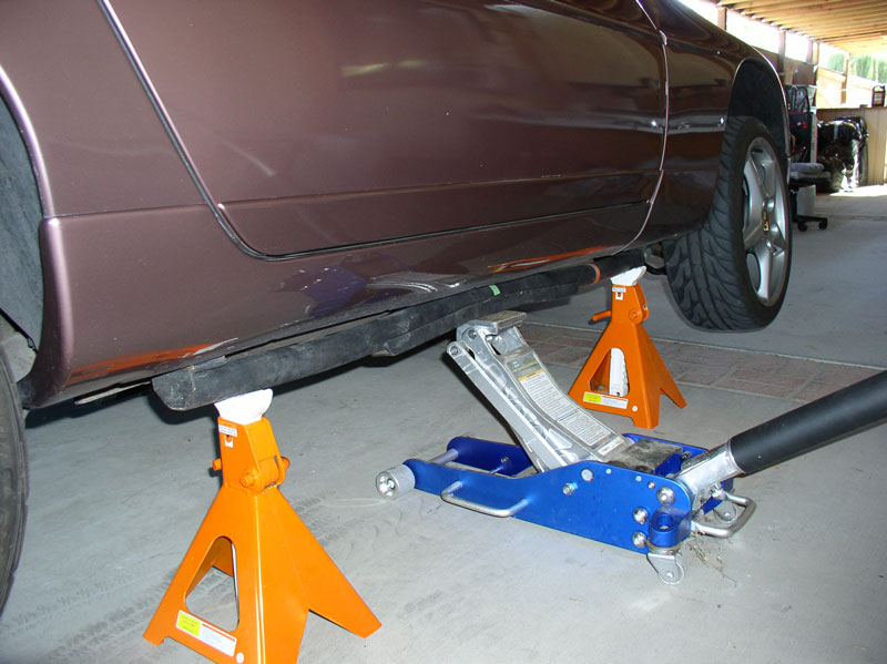
Then lifted the car using Porken�s lift bars and the Harbor Freight 6 Ton heavy duty jack stands. I raised the car as far as my floor jacks would lift in order to create as much room as possible to remove the transmission and rear suspension. I first lifted the car on both sides to the lowest setting on the jack stand then lifted again to maximum height of the floor jack. This seems to be the safer way to lift the car for this height.
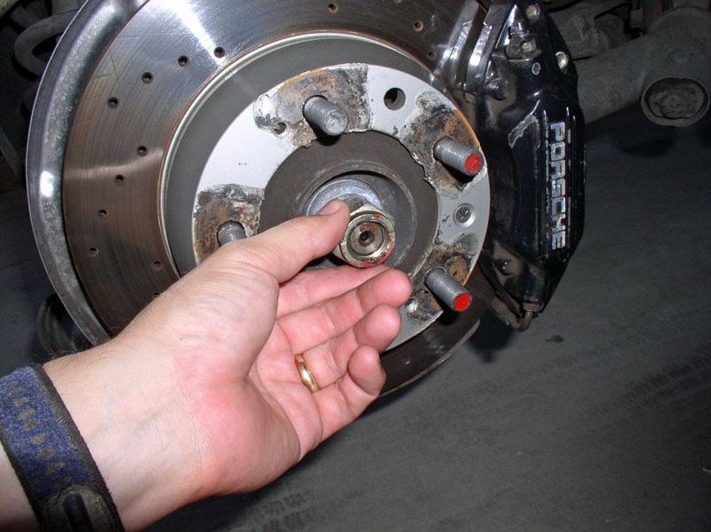
[CV Boot repair prep step] I removed the wheel next and the axle nut and washer. This step is not required unless you are removing the axle half shafts to repair the CV boots.
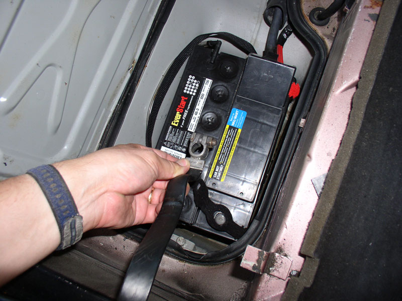
Next, I moved the driver�s seat all the way forward before disconnecting the battery. You will need to move the seat forward to access the parking brake cable in order to disconnect it later on.
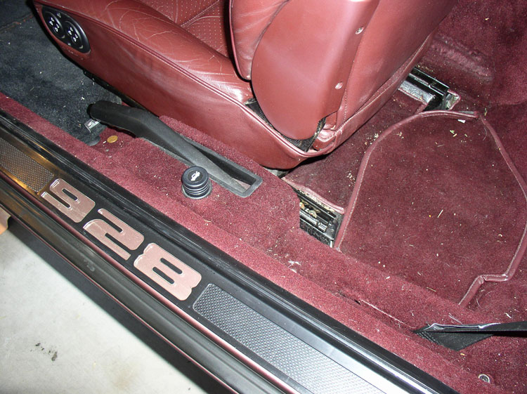
Disconnect the cable from the negative battery post.
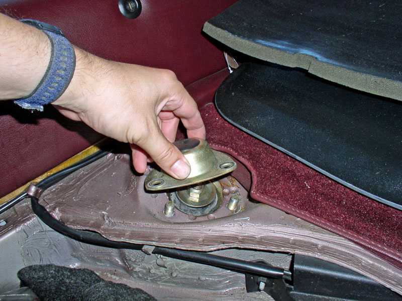
Remove the 17mm rear shock struts on both sides as shown�..
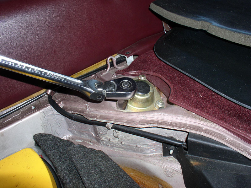
�.and remove the caps.
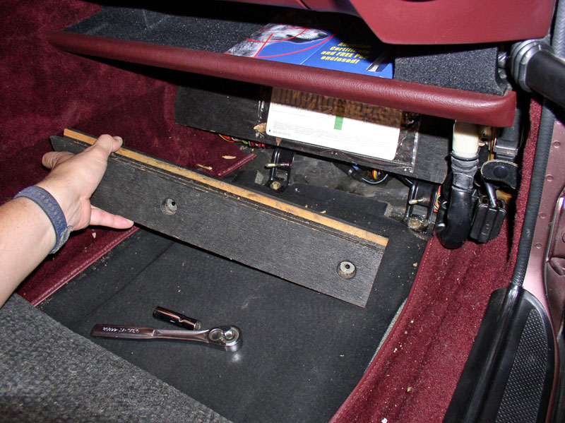
You will need to disconnect the transmission wiring harness at the spare tire compartment. To remove the plastic cover, remove the 10mm nut as shown.
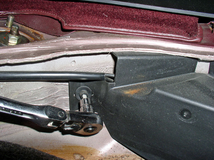
Pull the left side of the cover toward you and slide the right side of the cover forward to clear the two metal tabs holding it in place. Remove the plastic cover.
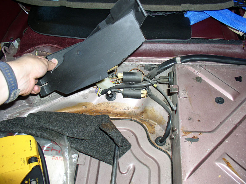
Use a Phillips screwdriver to detach this harness connector from the body as shown�.
�.and disconnect the harness. I used a small screwdriver on each side to pry up the plastic tabs enough to unlock the connector and separate.
Continued...
I took a little detour on this TT bearing replacement job to replace the rear half shaft CV Boots since Virginia�s were split�..
If you have the same issue, you can follow my steps to remove the half shafts. I will not be detailing the CV boot replacement procedure in this write up since I�ve covered that procedure in another write up. Otherwise, if your CV boots are in good shape, simply ignore the steps below that start with �[CV Boot repair prep step]�.
[CV Boot repair prep step] Since I was going to remove the half shafts, I needed to loosen the rear axle nuts while the car was still on the ground. I used a �� drive breaker bar with 32mm impact socket.
[CV Boot repair prep step] I blocked the tires as well as set the parking brake. Then you can use an extension pipe on the end of the breaker bar as shown�..
[CV Boot repair prep step] OR you can let gravity assist you if you weigh enough. I weigh about 250 pounds and simply stood on the end of the breaker bar and gave a little �bounce� and the nut came loose. This step is not required unless you are removing the axle half shafts to repair the CV boots.
I began by loosening the rear wheel lug nuts while I had weight on wheels.
Then lifted the car using Porken�s lift bars and the Harbor Freight 6 Ton heavy duty jack stands. I raised the car as far as my floor jacks would lift in order to create as much room as possible to remove the transmission and rear suspension. I first lifted the car on both sides to the lowest setting on the jack stand then lifted again to maximum height of the floor jack. This seems to be the safer way to lift the car for this height.
[CV Boot repair prep step] I removed the wheel next and the axle nut and washer. This step is not required unless you are removing the axle half shafts to repair the CV boots.
Next, I moved the driver�s seat all the way forward before disconnecting the battery. You will need to move the seat forward to access the parking brake cable in order to disconnect it later on.
Disconnect the cable from the negative battery post.
Remove the 17mm rear shock struts on both sides as shown�..
�.and remove the caps.
You will need to disconnect the transmission wiring harness at the spare tire compartment. To remove the plastic cover, remove the 10mm nut as shown.
Pull the left side of the cover toward you and slide the right side of the cover forward to clear the two metal tabs holding it in place. Remove the plastic cover.
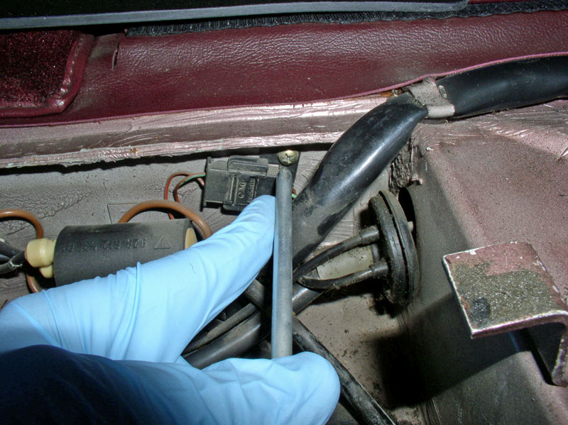
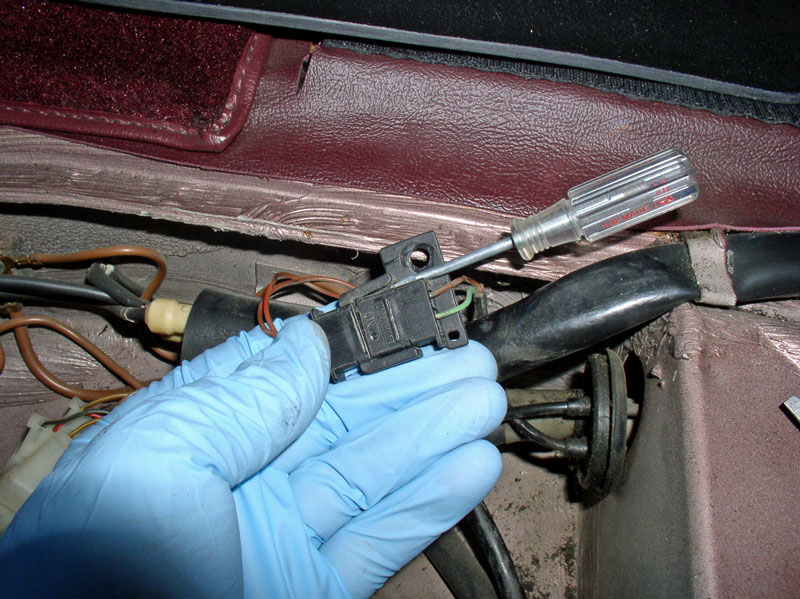
Use a Phillips screwdriver to detach this harness connector from the body as shown�.
�.and disconnect the harness. I used a small screwdriver on each side to pry up the plastic tabs enough to unlock the connector and separate.
Continued...
Trending Topics
12-19-2010, 02:04 PM
#8
Rennlist Member
Thread Starter
Join Date: Sep 2007
Location: Ridgecrest, California
Posts: 1,363
Likes: 0
Received 143 Likes
on
28 Posts
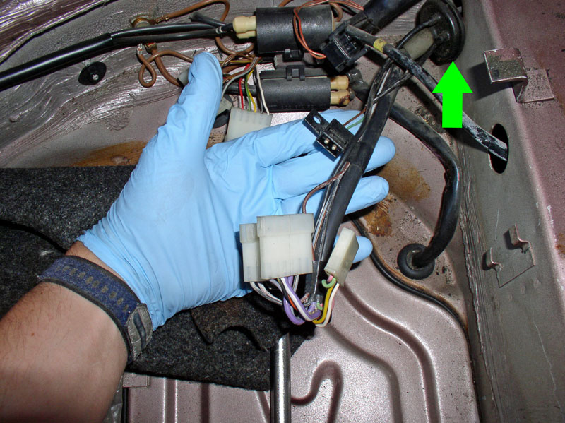
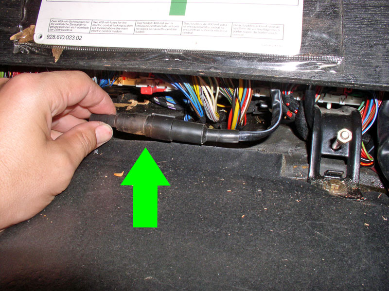
These three connectors will also have to be separated. Go ahead and disconnect them now.
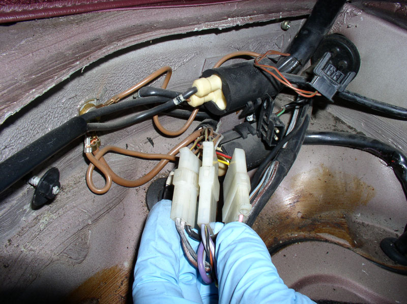
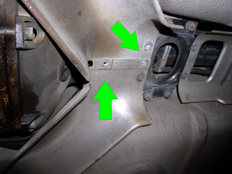
All together, the three white connectors and the one black connector will need to be pushed through the harness port as depicted by the green arrow in the picture below. You can push them through now or partially now and the rest of the way when you begin to lower the transmission.
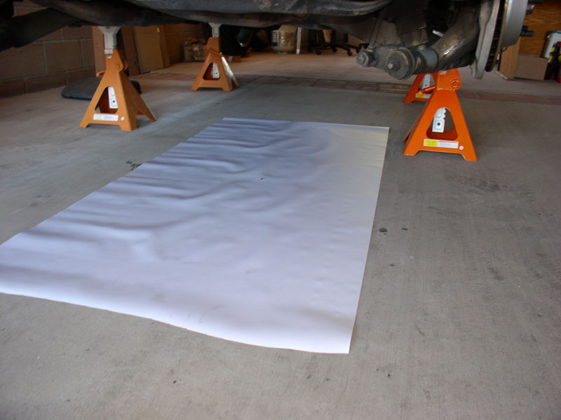
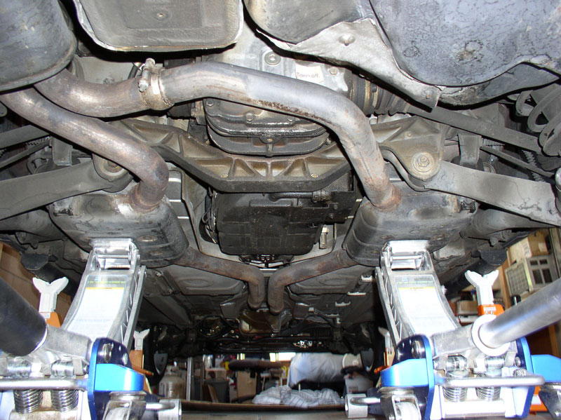
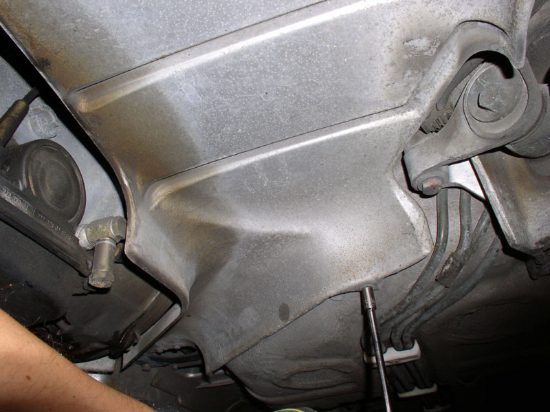
It�s a good idea to lay down a sheet of non-permeable material (such as a sheet of plastic shown below) under the transmission and Torque Converter (TC) as you will be draining transmission fluid and disconnecting hoses that will be leaking fluid. Also, remove the front two belly pans at this time. You will need a 10mm socket to remove the two 10mm bolts and you�ll need an 8mm socket and extension to remove all the 8mm screws.
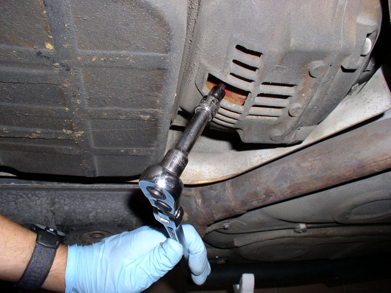
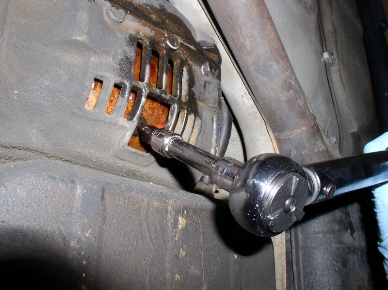
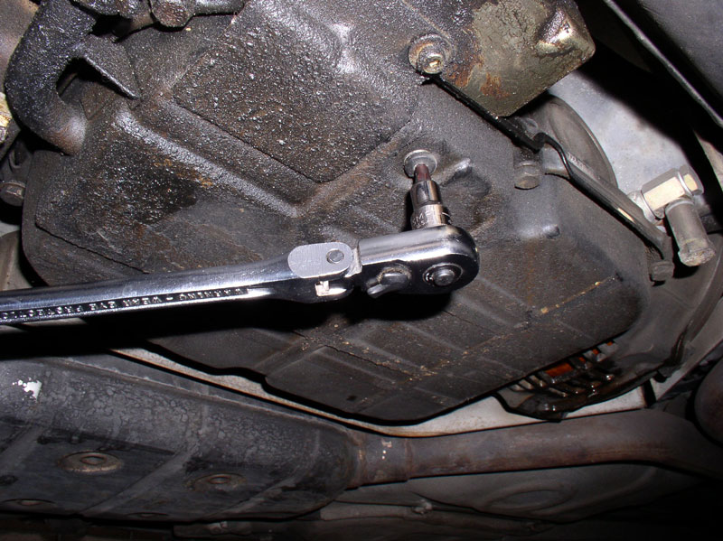
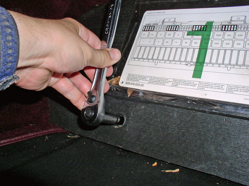
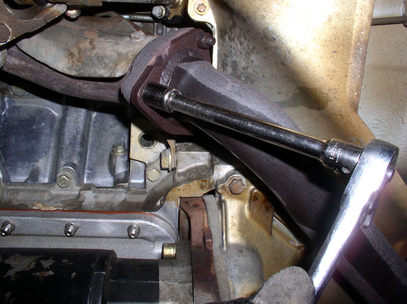
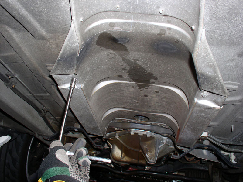
Next, I drained the transmission fluid from the TC and transmission fluid pan. In order to drain the TC, you will need to align the drain plug with the access port on the TC housing. This involves turning the engine crank shaft. I used a 27mm deep socket with a long handle �� ratchet.

I found it easiest to access the crank pulley bolt from underneath the front of the engine then rotated the crank CLOCKWISE (as you are standing in front of the car facing the engine)�..
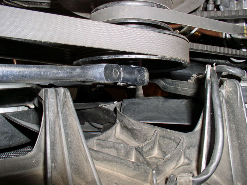
�. until the TC drain plug is lined up with the access port.
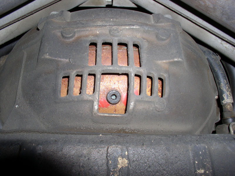
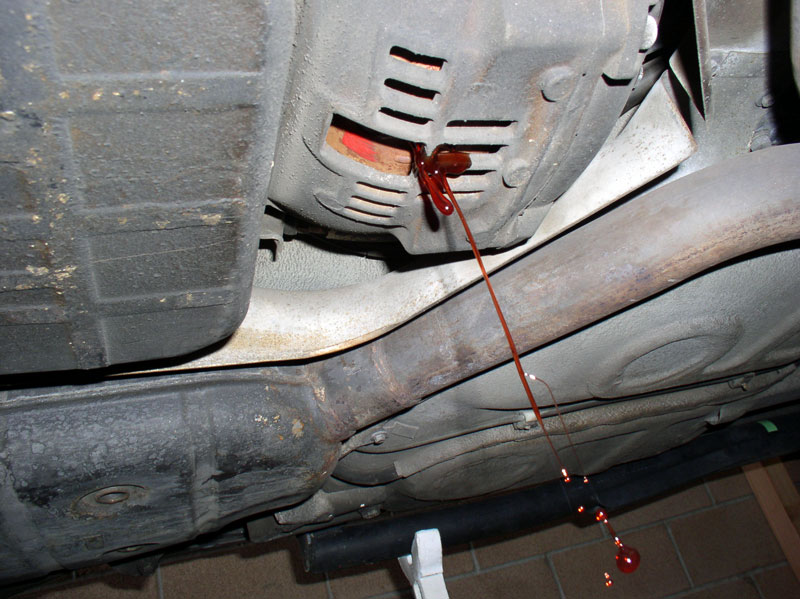
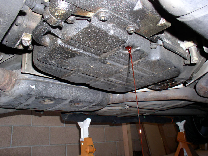
The drain plug takes a 5mm Allen head socket. Position your fluid catch pan under the drain plug. I would recommend using an EMPTY fluid drain pan to start. That way when you have drained all the fluid from the transmission, TC and hoses, you will know exactly how much fluid came out and can replace with exactly the same amount without guessing whether you have filled it too much or too little (assuming you had the correct fluid level in the first place).
Strawberry syrup!
It�s a good idea to inspect the TC drain plug sealing ring and replace if needed. The sealing ring looked new and since Virginia only has about 42K miles, I figured it had not been drained before. The rule of thumb I use for replacing the sealing rings like this one is to replace if it�s been removed and re-torqued more than 3 times (or if there�s signs of leakage, of course).
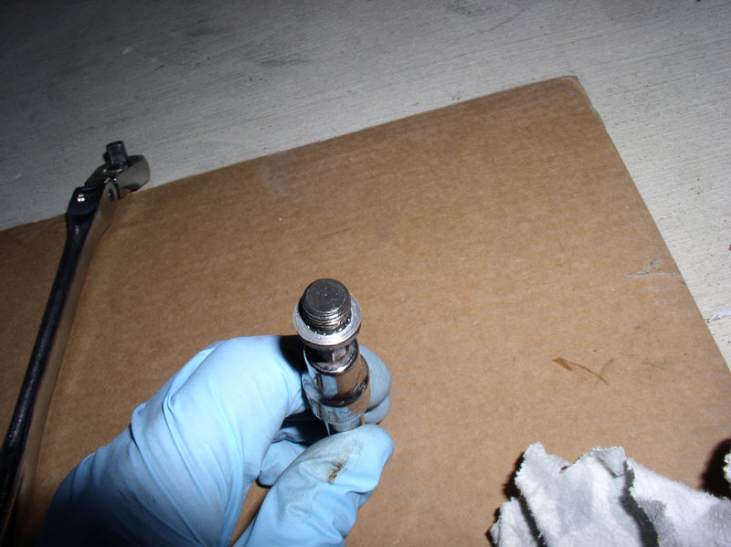
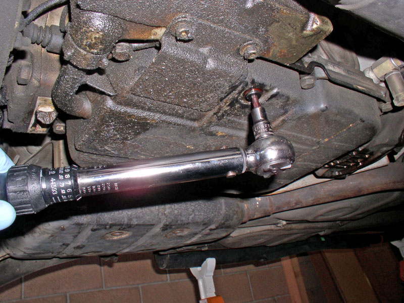
Replace the TC drain plug and torque to 7 ftlbs.
Using a 5mm Allen head socket, remove the transmission fluid pan drain plug��
�.and drain the transmission pan.
Inspect the sealing ring on the plug and replace is necessary. Re-install the drain plug and torque to 7 ftlbs. We�ll remove the transmission fluid reservoir later after we remove the exhaust system.
Next, I installed service covers and began preparing the engine bay.
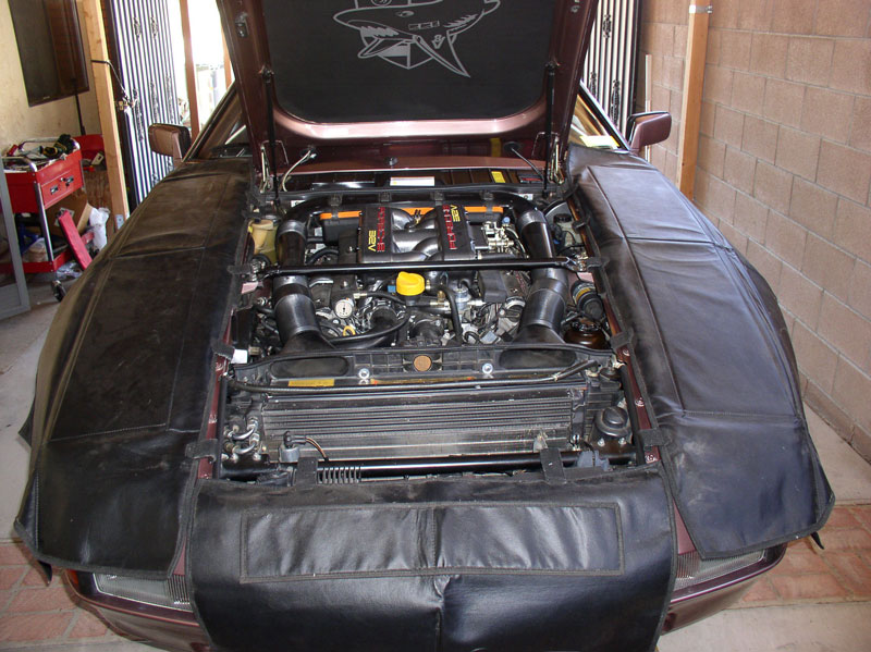
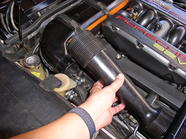
Remove the air guide tubes.
Continued...
All together, the three white connectors and the one black connector will need to be pushed through the harness port as depicted by the green arrow in the picture below. You can push them through now or partially now and the rest of the way when you begin to lower the transmission.
It�s a good idea to lay down a sheet of non-permeable material (such as a sheet of plastic shown below) under the transmission and Torque Converter (TC) as you will be draining transmission fluid and disconnecting hoses that will be leaking fluid. Also, remove the front two belly pans at this time. You will need a 10mm socket to remove the two 10mm bolts and you�ll need an 8mm socket and extension to remove all the 8mm screws.
Next, I drained the transmission fluid from the TC and transmission fluid pan. In order to drain the TC, you will need to align the drain plug with the access port on the TC housing. This involves turning the engine crank shaft. I used a 27mm deep socket with a long handle �� ratchet.
I found it easiest to access the crank pulley bolt from underneath the front of the engine then rotated the crank CLOCKWISE (as you are standing in front of the car facing the engine)�..
�. until the TC drain plug is lined up with the access port.
The drain plug takes a 5mm Allen head socket. Position your fluid catch pan under the drain plug. I would recommend using an EMPTY fluid drain pan to start. That way when you have drained all the fluid from the transmission, TC and hoses, you will know exactly how much fluid came out and can replace with exactly the same amount without guessing whether you have filled it too much or too little (assuming you had the correct fluid level in the first place).
Strawberry syrup!
It�s a good idea to inspect the TC drain plug sealing ring and replace if needed. The sealing ring looked new and since Virginia only has about 42K miles, I figured it had not been drained before. The rule of thumb I use for replacing the sealing rings like this one is to replace if it�s been removed and re-torqued more than 3 times (or if there�s signs of leakage, of course).
Replace the TC drain plug and torque to 7 ftlbs.
Using a 5mm Allen head socket, remove the transmission fluid pan drain plug��
�.and drain the transmission pan.
Inspect the sealing ring on the plug and replace is necessary. Re-install the drain plug and torque to 7 ftlbs. We�ll remove the transmission fluid reservoir later after we remove the exhaust system.
Next, I installed service covers and began preparing the engine bay.
Remove the air guide tubes.
Continued...
12-19-2010, 02:15 PM
#9
Rennlist Member
Thread Starter
Join Date: Sep 2007
Location: Ridgecrest, California
Posts: 1,363
Likes: 0
Received 143 Likes
on
28 Posts
Loosen the air hose clamp underneath the intake air housing as shown and remove the air filter box top and air filter.
Remove the 10mm nuts that hold the air box bottom half in place and remove the bottom half of the air box.
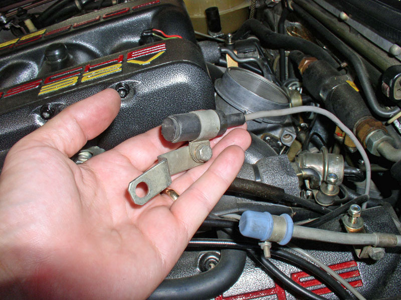
Disconnect the flywheel position sensor from its mounted position and set aside.
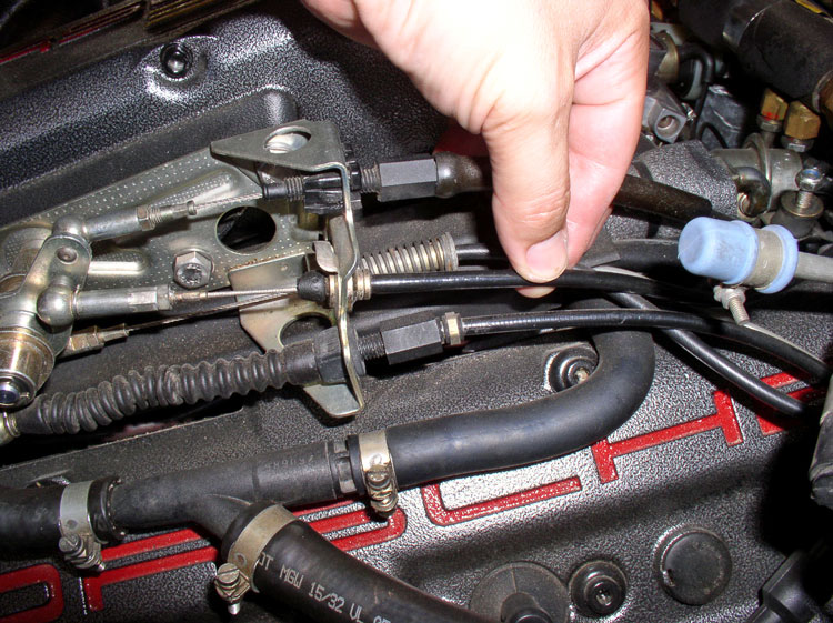
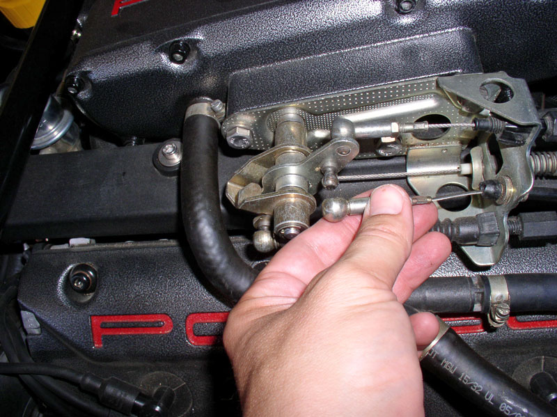
Next, you will disconnect the transmission Bowden cable that is used to help determine shift points based on accelerator position. It is the cable I�m grasping in the picture below.
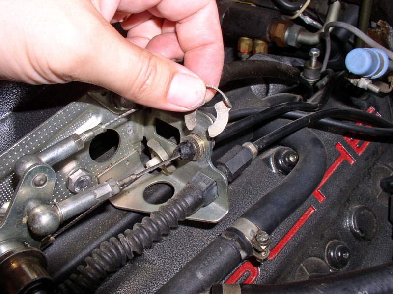
First, remove the retaining clip.
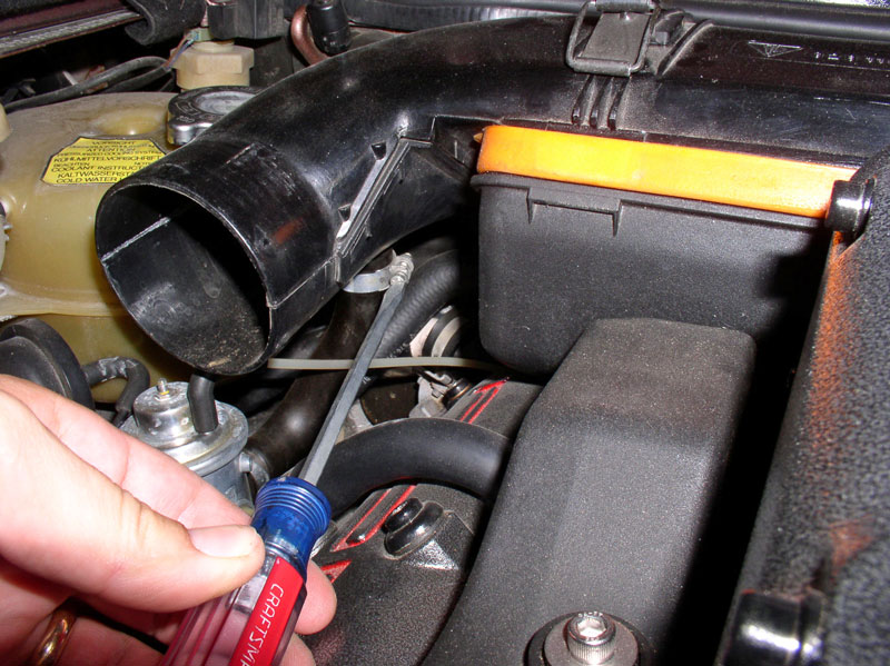
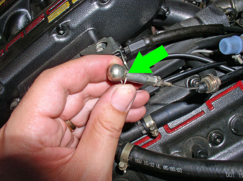
Next, you will need to remove the locking pin on the end of the cable. You can use a screwdriver to rotate the locking pin downward�..
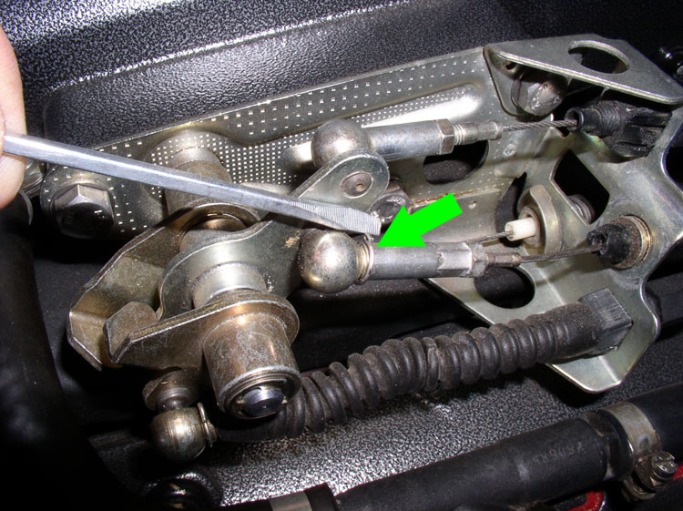
�.and slide it out (rearward).
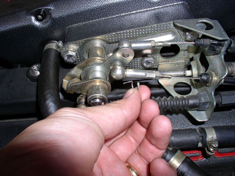
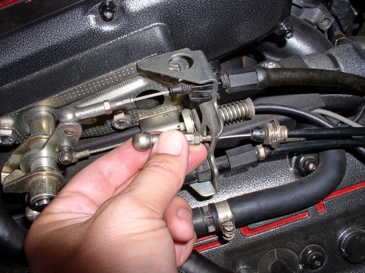
Next, pull the Bowden cable head off the accelerator linkage as shown.
Then push the cable back out through the linkage bracket as shown.
I would recommend re-installing the locking pin back into the cable head for safe keeping until it�s time to put it all back together.
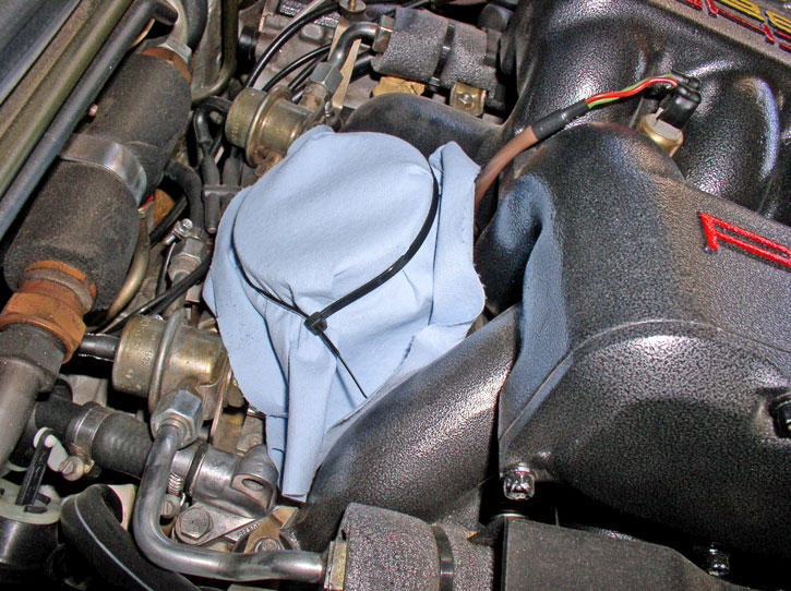
Lastly, once the air box is removed, I recommend covering the MAF. I just used a paper towel and zip tie as shown.
Next, we'll remove the exhaust system.
Remove the 10mm nuts that hold the air box bottom half in place and remove the bottom half of the air box.
Disconnect the flywheel position sensor from its mounted position and set aside.
Next, you will disconnect the transmission Bowden cable that is used to help determine shift points based on accelerator position. It is the cable I�m grasping in the picture below.
First, remove the retaining clip.
Next, you will need to remove the locking pin on the end of the cable. You can use a screwdriver to rotate the locking pin downward�..
�.and slide it out (rearward).
Next, pull the Bowden cable head off the accelerator linkage as shown.
Then push the cable back out through the linkage bracket as shown.
I would recommend re-installing the locking pin back into the cable head for safe keeping until it�s time to put it all back together.
Lastly, once the air box is removed, I recommend covering the MAF. I just used a paper towel and zip tie as shown.
Next, we'll remove the exhaust system.
12-19-2010, 02:41 PM
#10
Rennlist Member
Thread Starter
Join Date: Sep 2007
Location: Ridgecrest, California
Posts: 1,363
Likes: 0
Received 143 Likes
on
28 Posts
CH02 REMOVING EXHAUST SYSTEM
Removing the exhaust system will involve removing the Oxygen sensor (if equipped) either at the exhaust pipe or at the Central Electric Board (CEB). Since I was planning on replacing my O2 sensor, I decided to remove the sensor at the CEB. Use a 10mm socket to remove the two 10mm nuts that hold the lower CEB panel in place.
Remove the lower CEB panel cover and prop the upper CEB panel in the up position.
Peel back the carpet as shown and you will see the O2 sensor harness and the access port through the floor pan tunnel. Since I was removing the O2 sensor, I pressed out the floor pan grommet from the inside as pointed out by the arrow below.
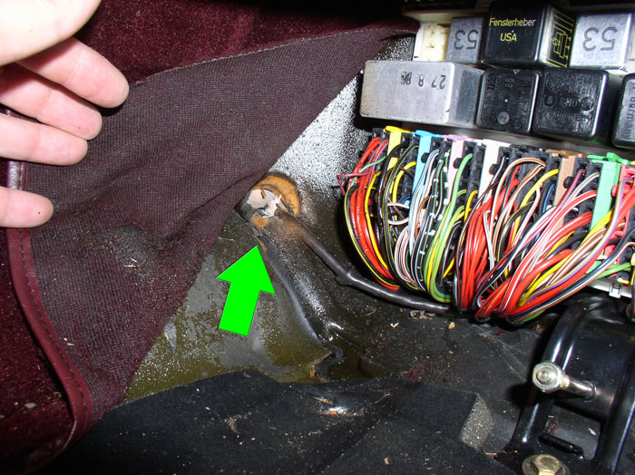
Follow the O2 sensor lead to the barrel connector as shown in the picture below. You can disconnect the O2 sensor from the harness by simply pulling apart the barrel connector. I left the O2 sensor lead in the car and pulled it out from underneath the car later on.
Back underneath the car I used WD-40 on the exhaust nuts to make removal easier.
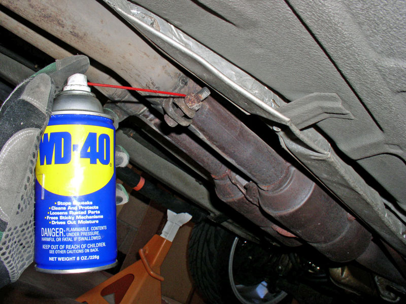
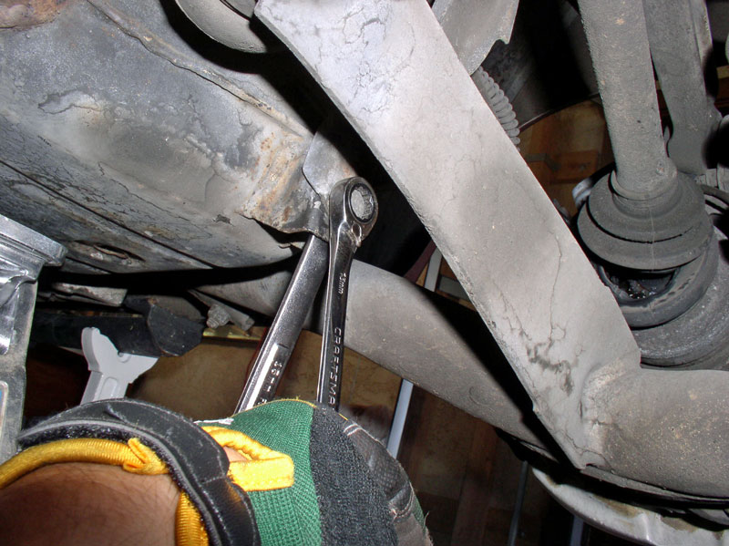
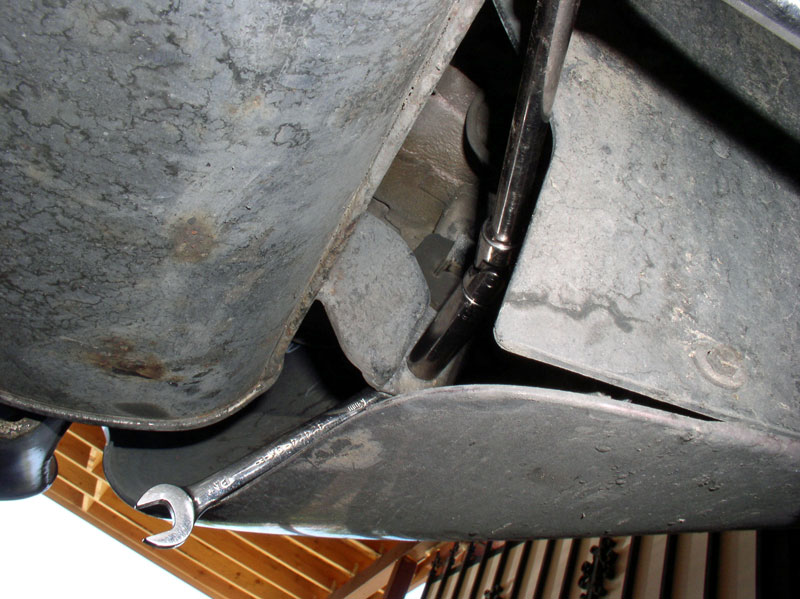
I used a 17mm wrench to loosen the clamps. Use the 17mm on the nut and a 15mm wrench to counter hold the bolt head. It�s not necessary to completely remove the nut.
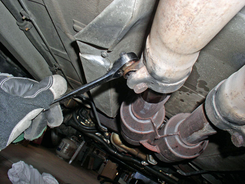
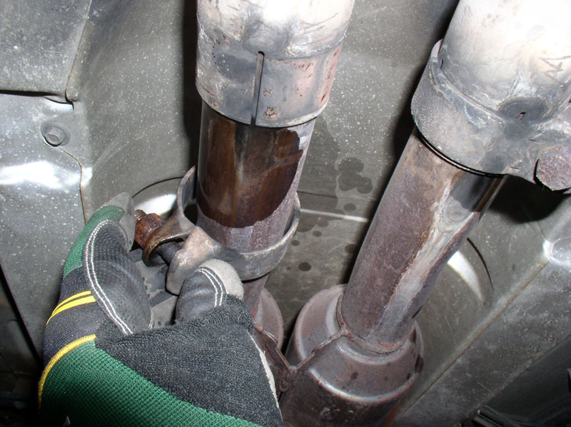
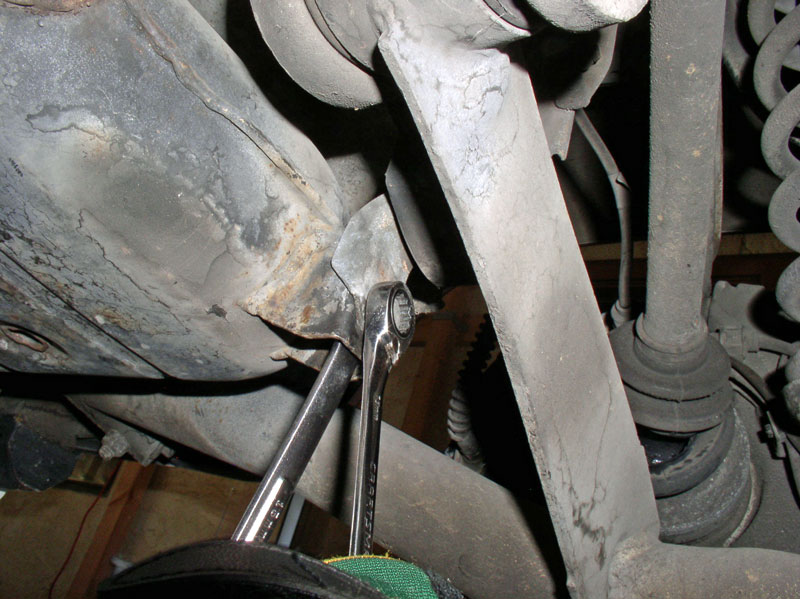
When the clamp is loose, slide it forward as shown.
I then pulled the O2 sensor lead out through the floor pan cutout.
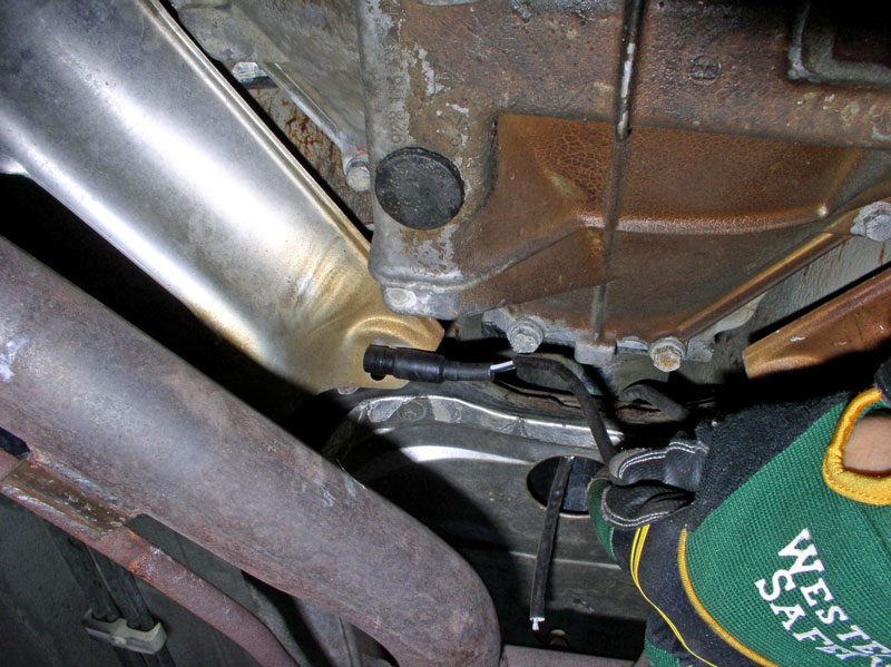
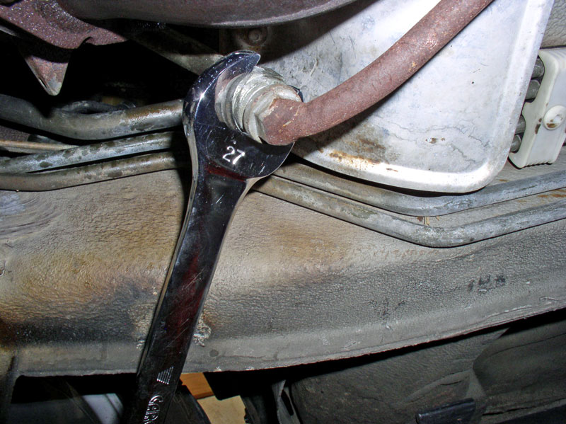
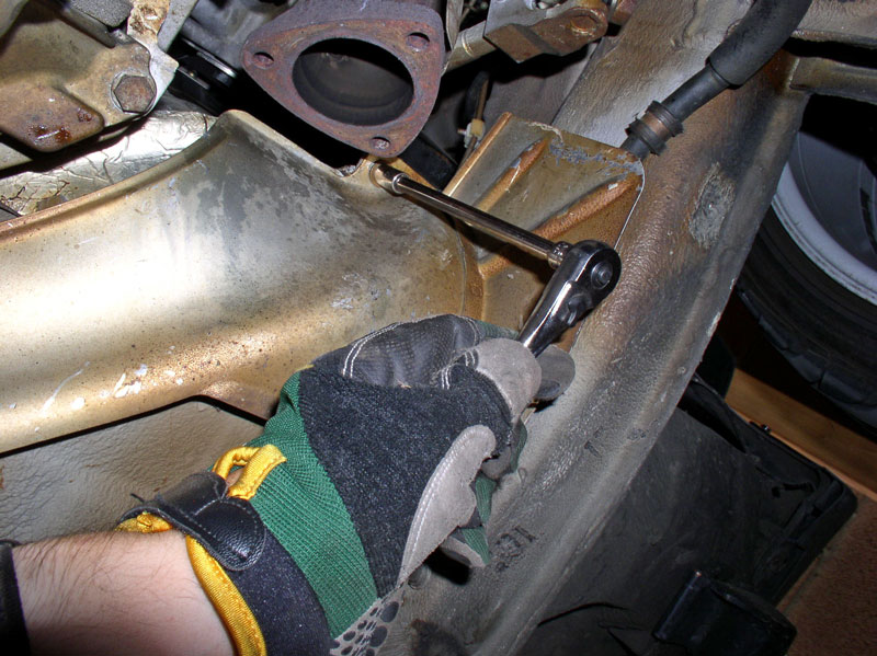
Next, use a 27mm wrench to loosen and disconnect the air pump hard line from the air tube to the catalytic converter. You may need to counter hold the air tube when loosening and WD-40 may be used if the nut is rusty or corroded.
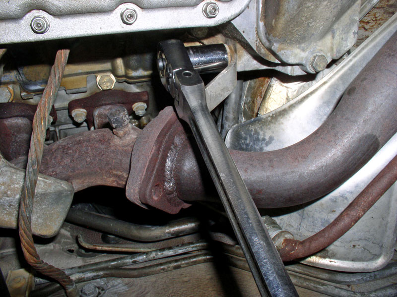
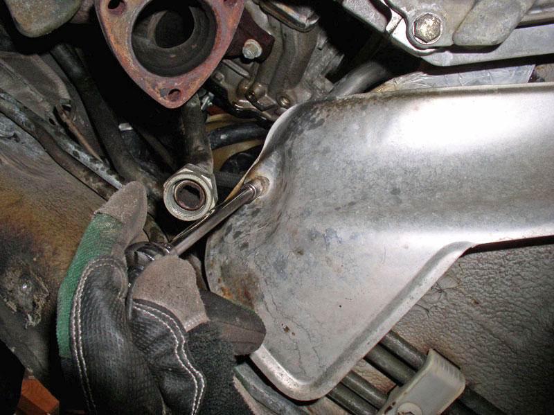
Support the catalytic converters from underneath with a hydraulic floor jack. Then loosen and remove the 13mm nuts that secure exhaust pipe to the exhaust manifold as shown below. There are 3 nuts on each side.
You may also have the support brace that attaches the exhaust pipe/manifold connection to the engine block as shown. Use a 19mm socket to remove these support braces. There�s one on each side of the engine. Be careful to support/hold the exhaust pipe while loosening as these are the last bolts that attach the exhaust pipe/cats to the engine.
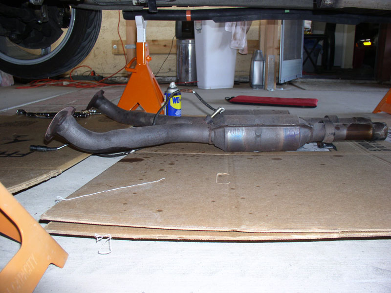
Lower the exhaust pipes and cats and inspect for damage. I will be replacing this assembly with an X-Pipe with High Flow CATS later on.
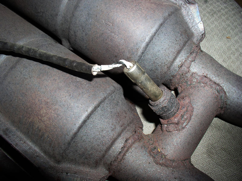
I noticed the O2 sensor had what appeared to be a splice in the sensor wire lead.

In addition, the O2 wires themselves were cracked at the O2 sensor. The car was running fine so it probably wasn�t causing any problems, yet. I opted to replace the O2 sensor since I was also installing the new X-Pipe and these wires were not instilling much confidence in future performance.
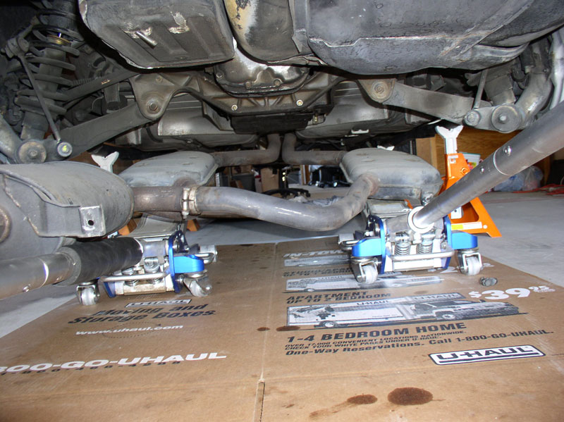
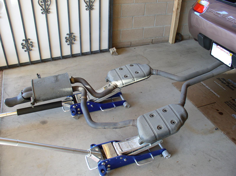
Next, remove the rear exhaust from behind the CATS. I used 2 hydraulic floor jacks and positioned them under the resonators to support the rear exhaust while it was being �disconnected� from the hangars.
Continued...
Removing the exhaust system will involve removing the Oxygen sensor (if equipped) either at the exhaust pipe or at the Central Electric Board (CEB). Since I was planning on replacing my O2 sensor, I decided to remove the sensor at the CEB. Use a 10mm socket to remove the two 10mm nuts that hold the lower CEB panel in place.
Remove the lower CEB panel cover and prop the upper CEB panel in the up position.
Peel back the carpet as shown and you will see the O2 sensor harness and the access port through the floor pan tunnel. Since I was removing the O2 sensor, I pressed out the floor pan grommet from the inside as pointed out by the arrow below.
Follow the O2 sensor lead to the barrel connector as shown in the picture below. You can disconnect the O2 sensor from the harness by simply pulling apart the barrel connector. I left the O2 sensor lead in the car and pulled it out from underneath the car later on.
Back underneath the car I used WD-40 on the exhaust nuts to make removal easier.
I used a 17mm wrench to loosen the clamps. Use the 17mm on the nut and a 15mm wrench to counter hold the bolt head. It�s not necessary to completely remove the nut.
When the clamp is loose, slide it forward as shown.
I then pulled the O2 sensor lead out through the floor pan cutout.
Next, use a 27mm wrench to loosen and disconnect the air pump hard line from the air tube to the catalytic converter. You may need to counter hold the air tube when loosening and WD-40 may be used if the nut is rusty or corroded.
Support the catalytic converters from underneath with a hydraulic floor jack. Then loosen and remove the 13mm nuts that secure exhaust pipe to the exhaust manifold as shown below. There are 3 nuts on each side.
You may also have the support brace that attaches the exhaust pipe/manifold connection to the engine block as shown. Use a 19mm socket to remove these support braces. There�s one on each side of the engine. Be careful to support/hold the exhaust pipe while loosening as these are the last bolts that attach the exhaust pipe/cats to the engine.
Lower the exhaust pipes and cats and inspect for damage. I will be replacing this assembly with an X-Pipe with High Flow CATS later on.
I noticed the O2 sensor had what appeared to be a splice in the sensor wire lead.
In addition, the O2 wires themselves were cracked at the O2 sensor. The car was running fine so it probably wasn�t causing any problems, yet. I opted to replace the O2 sensor since I was also installing the new X-Pipe and these wires were not instilling much confidence in future performance.
Next, remove the rear exhaust from behind the CATS. I used 2 hydraulic floor jacks and positioned them under the resonators to support the rear exhaust while it was being �disconnected� from the hangars.
Continued...
12-19-2010, 03:08 PM
#11
Rennlist Member
Thread Starter
Join Date: Sep 2007
Location: Ridgecrest, California
Posts: 1,363
Likes: 0
Received 143 Likes
on
28 Posts
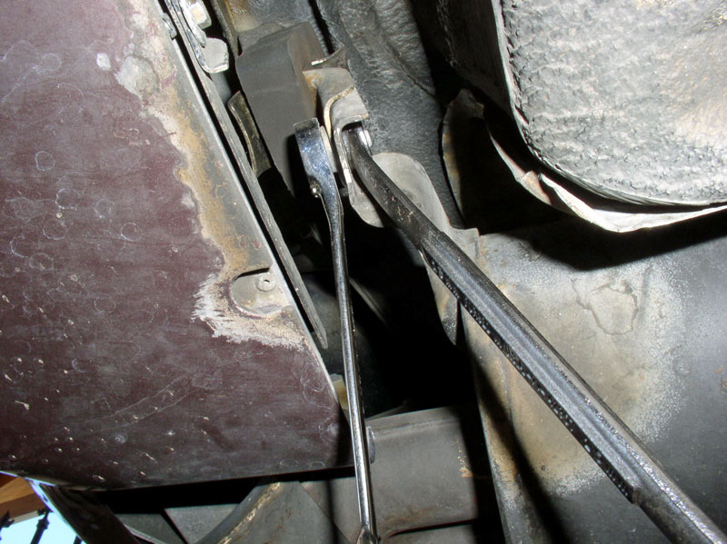
Use two 13mm wrenches to loosen and disconnect the resonator from the exhaust hanger on the passenger side.
Do the same with the hanger on the driver�s side.
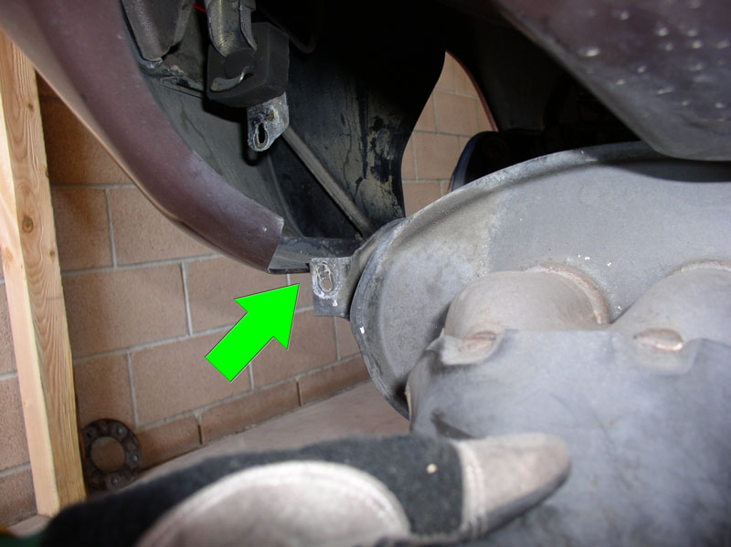
There�s another hanger attached to the side of the rear muffler. You can reach the 13mm nut and bolt as shown in the pic below. It is also easier to access this bolt/nut if you remove the rearward splash guard of the driver�s side rear wheel well.
Lastly, loosen and disconnect the 13mm bolt/nut from the rear hanger just behind the rear muffler and battery box. At this point, the rear exhaust system will be free from the car�.
Before removing the exhaust system, you will need to carefully maneuver the rear muffler hanger support tab to clear the bottom of the rear bumper cover as shown in the picture below.
Once it�s clear, you can lower the hydraulic jacks�..
�.and pull the rear exhaust system from the car. The rear of the system will be heavier than the front so tip the muffler up when pulling back so the pipes at the front will clear the rear bumper without scratching the paint.
Next, remove the heat shields. I started with the 2 rear shields. All the heat shields are secured using 8mm metal screws. Remove the 4 screws identified in the pic below.
Remove the remaining 8mm screws for each rear heat shield and remove the shields.
Remove the securing screws for the center heat shield and remove the center shield.
I removed the front, passenger side heat shield. It�s held in place with two 8mm screws.
I went ahead and removed the driver�s side heat shield as well.
Next, remove the forward cross brace. It is secured with four 13mm bolts.
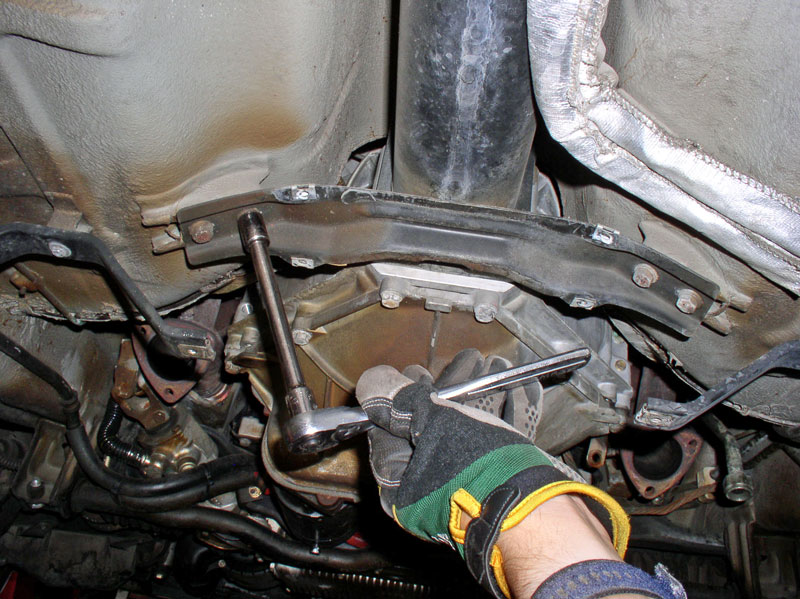
Finally, remove the rear cross brace. It is secured with four 13mm bolts.
Do the same with the hanger on the driver�s side.
There�s another hanger attached to the side of the rear muffler. You can reach the 13mm nut and bolt as shown in the pic below. It is also easier to access this bolt/nut if you remove the rearward splash guard of the driver�s side rear wheel well.
Lastly, loosen and disconnect the 13mm bolt/nut from the rear hanger just behind the rear muffler and battery box. At this point, the rear exhaust system will be free from the car�.
Before removing the exhaust system, you will need to carefully maneuver the rear muffler hanger support tab to clear the bottom of the rear bumper cover as shown in the picture below.
Once it�s clear, you can lower the hydraulic jacks�..
�.and pull the rear exhaust system from the car. The rear of the system will be heavier than the front so tip the muffler up when pulling back so the pipes at the front will clear the rear bumper without scratching the paint.
Next, remove the heat shields. I started with the 2 rear shields. All the heat shields are secured using 8mm metal screws. Remove the 4 screws identified in the pic below.
Remove the remaining 8mm screws for each rear heat shield and remove the shields.
Remove the securing screws for the center heat shield and remove the center shield.
I removed the front, passenger side heat shield. It�s held in place with two 8mm screws.
I went ahead and removed the driver�s side heat shield as well.
Next, remove the forward cross brace. It is secured with four 13mm bolts.
Finally, remove the rear cross brace. It is secured with four 13mm bolts.
12-19-2010, 03:25 PM
#12
AutoX

Join Date: Sep 2010
Posts: 13
Likes: 0
Received 0 Likes
on
0 Posts
Dwayne - my hats off to you - this is very impressive stuff! If you're not a professional mechanic, I would like to know what you do for a living. Just fantastic, very helpful even to me, and I am a professional mechanic. By the way, the car in the picture appears to have the same burgundy interior as my '83, which I'm in the middle of returning to correct. That leather is no longer available, and has turned into quite the project for me. I'm now 8 months into it with no real end in sight, so take good care of yours. I guess if you own 6 of these cars, you probably know just about everything there is to know already.
Ben
Ben
12-19-2010, 03:35 PM
#13
Rennlist Member
Your timing is fantastic Dwayne.............I just spoke with Constantine this week re. his super bearings and super clamp.
I now have some great reading in these cold dark days of winter of your latest epic...........thanks so much.
I now have some great reading in these cold dark days of winter of your latest epic...........thanks so much.


