
1965 Imp 911 - a baby 911 in making....


 05-17-2022, 05:46 AM
#34
Advanced
Thread Starter
Time to mount up.
First thing was to remove the air from the nearside chassis rail. It was a bit frilly right where I want to bolt a crossmember..
.jpg)
I bought some bobbin style rubber mounts, 60 in hardness, from the local engineering shop. They are British made mounts so somehow they will probably leak.
I cut some plates that then bolted to the stock Subaru gearbox mount points. Then shuffled the engine/box into the position I wanted it to sit. I had measured the level at which Imp one sat on the ground, finding that the bottom of the rear side windows were pretty much level. I set Imp two up on the hoist at the same level and made sure it was level across the car. Marked things, measured things, checked clearances. Once happy with all that I got some cardboard and started making little shapes with folds out of it. Added a bobbin and the other end went through the original Imp gearbox chassis mount, hole enlarged a mm to take a 10mm stud.
.jpg)
Kept trying them until things looked good and transferred the shape to steel. Bent the shape in the... bender.
.jpg)
.jpg)
Tacked in place..
.jpg)
.jpg)
Removed to be reinforced and fully welded..
.jpg)
_(1).jpg)
_(1).jpg)
Finished and fitted...
.jpg)
.jpg)
Now for the front of the engine.
Or is that the back of the engine?
The other end. I plonked a bit of steel in place.
.jpg)
I didn't want to go much lower than the sump. I went for some low profile bobbins that were ideal. Cut some more plate to suit and drilled, tapped, bolted them in place on the engine end plate. Played with more cardboard and then steel, folded and tacked till I had things that held bobbins.
.jpg)
welded them up..
.jpg)
.jpg)
Next job was to make a crossmember.
Now there was going to be lots of moving this engine/box in and out of position. Not just now while building the crossmember but in the future of the build as I do exhausts/piping/induction etc. The huge steel bench we have in the workshop that I had been moving the engine in and out on was just that - huge, heavy and often in the way. Plus its set in height so when I wanted to move the engine position up and down it was via the car hoist which is not exactly finely controlled.
I needed a bespoke engine table that was easily height adjustable.
Enter stage left the 'Engine cart 2000'..
.jpg)
I whipped that lot above in one evening using an old height adjustable Bedford truck seat base, some spare steel offcuts from the steel rack and some budget castor wheels from Mitre 10. I added some plywood for the top and then I sat on it whilst twiddling the **** - which made things go up.
And down. It was designed to match up with the main workbench in height so I could slide the engine and box straight on. Engine and box are quite light as they are and I can shift them about easily but that wont last when the flywheel/clutch/pistons/heads/gearbox internals are all back in their rightful homes.
I painted it grey because I don't like blue steel and Mitre 10 had loads of plasticoat spray paint on clearance.
_(Custom).jpg)
I couldn't help but mask the old sticker on the seat base..
.jpg)
Hannah varnished the plywood so it looked pretty. But then I realised that sliding the engine off and on was going to ruin the ply, nor was plywood a very slidey surface. So a bit of old stainless kitchen bench got cut up for the top layer.
.jpg)
Now in action..
.jpg)
Aint that just so cute.
Way easier to move the lot about the workshop and into position under the car- which now handily sits a bit higher in the air which was nice for the next stage.
_(Custom).jpg)
Crossmember time.
I wanted this to be more organic/factory looking then the simple box section one holding the Datsun up. It had to be strong and allow plenty of space for exhaust pipes heading backwards to a silencer assembly that will be slung under the rear valence. It also had remove easily from the car, ideally still attached to the engine if need be.
I started by making some mount points that would bolt in and out easily onto the chassis rails. Captive nuts welded on some angle iron that sits on the inside of the rails. 4 bolts per side. These bolted in place with 3mm alloy spacers on each side to allow for differences between this car and Imp one, which I know has rails a few mm closer.
Plasma cut a strip 50mm wide from 3mm mild steel plate. Welded some mounts on it to suit the bobbins hanging from the engine. Bent a curve in the plate till it sat where I wanted and had the shape I desired. Then started cutting cardboard again...
.jpg)
and transferring it to steel...
.jpg)
Tacked it altogether..
.jpg)
Added tubes to it for easy access to the engine mount nuts which made for a cleaner look. I could close off the angles on top and make it all pretty like.
.jpg)
.jpg)
I welded what I could on the inside of the crossmember. I really didn't want exposed welds on the outside or any lumps. Then welded the outside. I had to be strategic because even though it was all 3mm steel it would still move a heap as the welds cooled- shrink on the welded edge and shorten or lengthen the whole length either way. My final welds had to pull it back out in length as they cooled and shrunk so it matched the rails. To much relief I got it pretty much bang on and it all still lined up sweet.
.jpg)
.jpg)
.jpg)
The whole time I was building this bugger I was thinking 'ooh this is going to be hefty..' and stressing. Trying to find a happy medium between strength and weight but strength really was the most important thing. I didn't want my engine to fall on the road. As it was it turned out ok. Not a bad weight at all. I hung it on some scales..
.jpg)
.jpg)
Not bad at all. Just a smidge heavier than the alternator for example. Certainly brute enough. I was happy.
I bolted the whole lot in place, lowered the wheely cart 2000 out of the way and there it sat, engine and box finally suspended on their own mounts.
Beautiful I thought.
So beautiful that I had to take the car off the hoist and snap some pics...
.jpg)
.jpg)
.jpg)
Would ya look at that. Damn that looks cool. I was ****ing stoked. This was a big occasion. I patted myself on the back and then took some more pics and measured some things..
Clearance under the car was great. The crossmember was only about 10mm lower than the exhaust on IMP one however this was also far further forward. It'll be gravy.
.jpg)
.jpg)
The room between the inlet faces on the heads and what would be the underside of the parcel shelf was almost bang on what I had very originally measure it to be when I first mocked the untouched engine up under Imp one. About 170mm..
.jpg)
.jpg)
Neat. I'd better start ordering some induction goodies eh.
So that's that. Engine is now a bolt in thing. When the time comes I'll be transferring this crossmember along with the suspension crossmember over to Impy one. But I'm a long way from that point.
I put Imp two back on the hoist, gracefully rolled the engine cart 2000 back in place, 'UNBOLTED' the engine and box and rolled it away. Engine was slid back onto the bench and I am now going to look at making a custom alternator drive pulley and mounting the alternator (probably the old prelude/civic item I scored from the wreckers)
I have also been looking into the exhaust. I'm doing some research and trying suss out what to do about headers. Either modifying what I have or making bespoke ones. But that's another story and will be my next installment.
First thing was to remove the air from the nearside chassis rail. It was a bit frilly right where I want to bolt a crossmember..
I bought some bobbin style rubber mounts, 60 in hardness, from the local engineering shop. They are British made mounts so somehow they will probably leak.
I cut some plates that then bolted to the stock Subaru gearbox mount points. Then shuffled the engine/box into the position I wanted it to sit. I had measured the level at which Imp one sat on the ground, finding that the bottom of the rear side windows were pretty much level. I set Imp two up on the hoist at the same level and made sure it was level across the car. Marked things, measured things, checked clearances. Once happy with all that I got some cardboard and started making little shapes with folds out of it. Added a bobbin and the other end went through the original Imp gearbox chassis mount, hole enlarged a mm to take a 10mm stud.
Kept trying them until things looked good and transferred the shape to steel. Bent the shape in the... bender.
Tacked in place..
Removed to be reinforced and fully welded..
Finished and fitted...
Now for the front of the engine.
Or is that the back of the engine?
The other end. I plonked a bit of steel in place.
I didn't want to go much lower than the sump. I went for some low profile bobbins that were ideal. Cut some more plate to suit and drilled, tapped, bolted them in place on the engine end plate. Played with more cardboard and then steel, folded and tacked till I had things that held bobbins.
welded them up..
Next job was to make a crossmember.
Now there was going to be lots of moving this engine/box in and out of position. Not just now while building the crossmember but in the future of the build as I do exhausts/piping/induction etc. The huge steel bench we have in the workshop that I had been moving the engine in and out on was just that - huge, heavy and often in the way. Plus its set in height so when I wanted to move the engine position up and down it was via the car hoist which is not exactly finely controlled.
I needed a bespoke engine table that was easily height adjustable.
Enter stage left the 'Engine cart 2000'..
I whipped that lot above in one evening using an old height adjustable Bedford truck seat base, some spare steel offcuts from the steel rack and some budget castor wheels from Mitre 10. I added some plywood for the top and then I sat on it whilst twiddling the **** - which made things go up.
And down. It was designed to match up with the main workbench in height so I could slide the engine and box straight on. Engine and box are quite light as they are and I can shift them about easily but that wont last when the flywheel/clutch/pistons/heads/gearbox internals are all back in their rightful homes.
I painted it grey because I don't like blue steel and Mitre 10 had loads of plasticoat spray paint on clearance.
I couldn't help but mask the old sticker on the seat base..
Hannah varnished the plywood so it looked pretty. But then I realised that sliding the engine off and on was going to ruin the ply, nor was plywood a very slidey surface. So a bit of old stainless kitchen bench got cut up for the top layer.
Now in action..
Aint that just so cute.
Way easier to move the lot about the workshop and into position under the car- which now handily sits a bit higher in the air which was nice for the next stage.
Crossmember time.
I wanted this to be more organic/factory looking then the simple box section one holding the Datsun up. It had to be strong and allow plenty of space for exhaust pipes heading backwards to a silencer assembly that will be slung under the rear valence. It also had remove easily from the car, ideally still attached to the engine if need be.
I started by making some mount points that would bolt in and out easily onto the chassis rails. Captive nuts welded on some angle iron that sits on the inside of the rails. 4 bolts per side. These bolted in place with 3mm alloy spacers on each side to allow for differences between this car and Imp one, which I know has rails a few mm closer.
Plasma cut a strip 50mm wide from 3mm mild steel plate. Welded some mounts on it to suit the bobbins hanging from the engine. Bent a curve in the plate till it sat where I wanted and had the shape I desired. Then started cutting cardboard again...
and transferring it to steel...
Tacked it altogether..
Added tubes to it for easy access to the engine mount nuts which made for a cleaner look. I could close off the angles on top and make it all pretty like.
I welded what I could on the inside of the crossmember. I really didn't want exposed welds on the outside or any lumps. Then welded the outside. I had to be strategic because even though it was all 3mm steel it would still move a heap as the welds cooled- shrink on the welded edge and shorten or lengthen the whole length either way. My final welds had to pull it back out in length as they cooled and shrunk so it matched the rails. To much relief I got it pretty much bang on and it all still lined up sweet.
The whole time I was building this bugger I was thinking 'ooh this is going to be hefty..' and stressing. Trying to find a happy medium between strength and weight but strength really was the most important thing. I didn't want my engine to fall on the road. As it was it turned out ok. Not a bad weight at all. I hung it on some scales..
Not bad at all. Just a smidge heavier than the alternator for example. Certainly brute enough. I was happy.
I bolted the whole lot in place, lowered the wheely cart 2000 out of the way and there it sat, engine and box finally suspended on their own mounts.
Beautiful I thought.
So beautiful that I had to take the car off the hoist and snap some pics...
Would ya look at that. Damn that looks cool. I was ****ing stoked. This was a big occasion. I patted myself on the back and then took some more pics and measured some things..
Clearance under the car was great. The crossmember was only about 10mm lower than the exhaust on IMP one however this was also far further forward. It'll be gravy.
The room between the inlet faces on the heads and what would be the underside of the parcel shelf was almost bang on what I had very originally measure it to be when I first mocked the untouched engine up under Imp one. About 170mm..
Neat. I'd better start ordering some induction goodies eh.
So that's that. Engine is now a bolt in thing. When the time comes I'll be transferring this crossmember along with the suspension crossmember over to Impy one. But I'm a long way from that point.
I put Imp two back on the hoist, gracefully rolled the engine cart 2000 back in place, 'UNBOLTED'
the engine and box and rolled it away. Engine was slid back onto the bench and I am now going to look at making a custom alternator drive pulley and mounting the alternator (probably the old prelude/civic item I scored from the wreckers)I have also been looking into the exhaust. I'm doing some research and trying suss out what to do about headers. Either modifying what I have or making bespoke ones. But that's another story and will be my next installment.
Last edited by yoeddynz; 05-17-2022 at 05:42 PM. Reason: Missed a photo
05-17-2022, 01:36 PM
#35
Three Wheelin'
like isn't enough. we need a love button. hah.
The following users liked this post:
yoeddynz (05-17-2022)
05-18-2022, 06:59 AM
#37
Advanced
Thread Starter
Look at this lot I have to play with.
Here's a head. Lovely little things. Nicely made. Very clean and simple. Brilliant hemi design. Not sure on the valve angles but I could picture it flowing nicely (based on the knowledge of my mildly edumacated mind about such technical enginy things, stuff gained from reading old cars and car conversion books etc)
.jpg)
I measured the valves. The inlet is a fairly decent 33mm thereabouts.
.jpg)
Exhaust 28mm
.jpg)
Not bad. Not bad at all really. I dunno if they have anything mildly flash like a 3 angle seat. I suspect not. Goldwings are a pay grade above such frilvolous race engine nonsense. But I think I do happen to have a valve grinding setup and some seat cutters amongst the engine reconditioning stuff I was given a year or so ago.
Anyway.. I won't get too excited because as far as maximum flow at stratospheric revs go it heads downhill from the valve sizes. Just look at the size of this inlet port...
.jpg)
25mm Extravagance ! Not really much room to open it out either, nor risk mucking about with the port innards. Too risky.
Now the other end of the equation.
.jpg)
Exhaust port is 28mm one way and 23 the other. I think its cast like that on purpose to aid the low engine speed air flow (these engines are all about torque... and I'll probably mention that several times as I go on, just as I take a sip of my finest scotch. Lets not mention those dirty words like bhp and redlines)
The exhaust headers are comical. But I shouldn't really laugh because I know full well that the technical boffins at Honda know a heck of a lot more than me about cylinder head flow and tuning engines to suit bikes that are made to cruise all day long for a lifespan in the vicinity of 1,000,000 miles.
But still. They are funny..
.jpg)
At first glance one might be fooled into thinking they are maybe 26- 28mm like the ports. But they step down to an internal diameter of 23mm. Outside measures ap at around 26mm.
.jpg)
The valkyrie items are not bigger from what I can gather. They just have a poncy bit of shiny chrome tube over them so they look bigger..and shiny.
So there we have it.
Plans thus far.
My intention is to start the induction side with some bmw k75 itbs, injectors mounted into custom flanges to suit. They are about 34mm thereabouts so hugely more than big enough. They are not perfect though and will involve a bit of tinkering because the K series of engines have port spacing at 75mm and the Goldwing ports are spaced at 90mm. But they are separate and things could be adapted I'm sure.
These ..
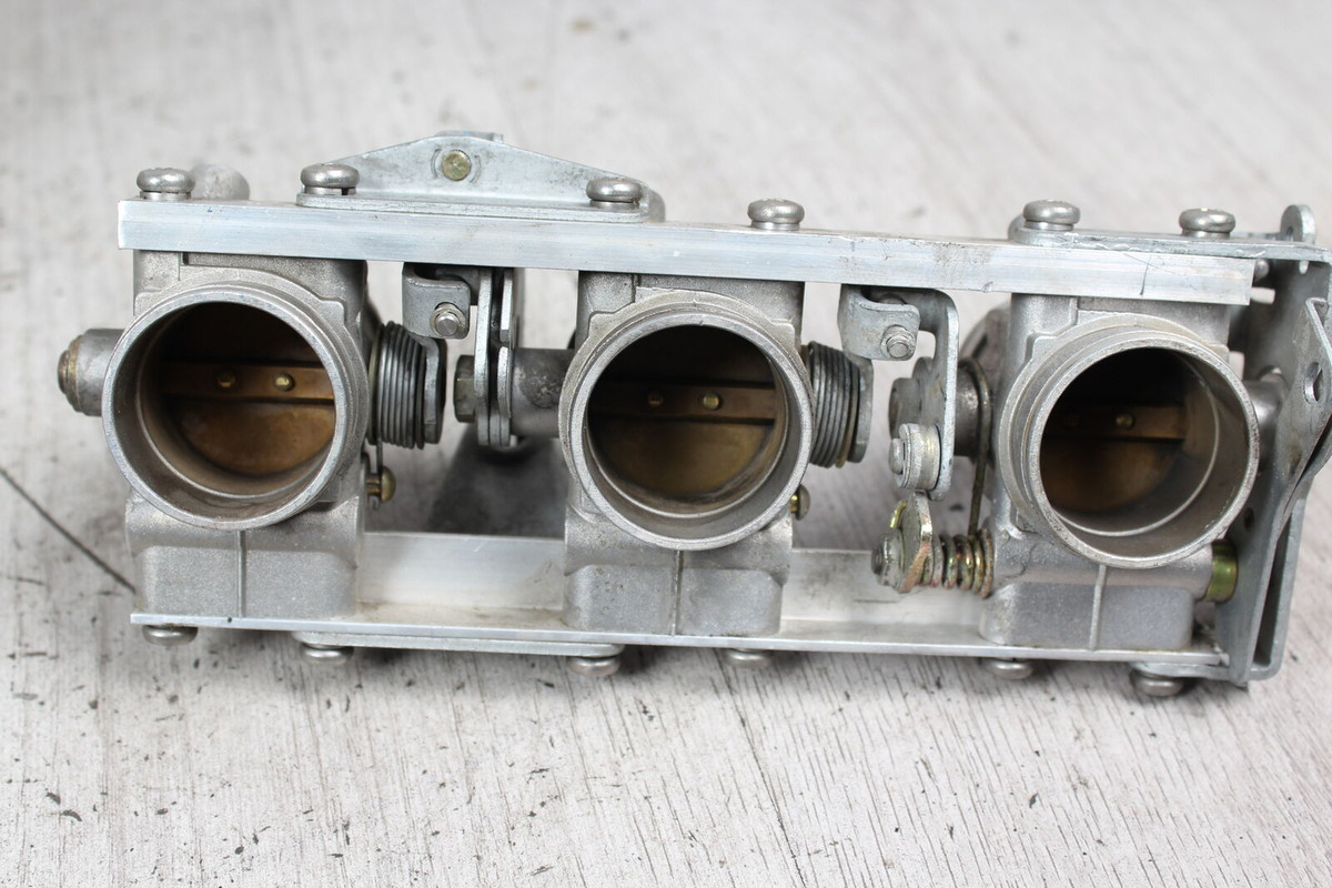
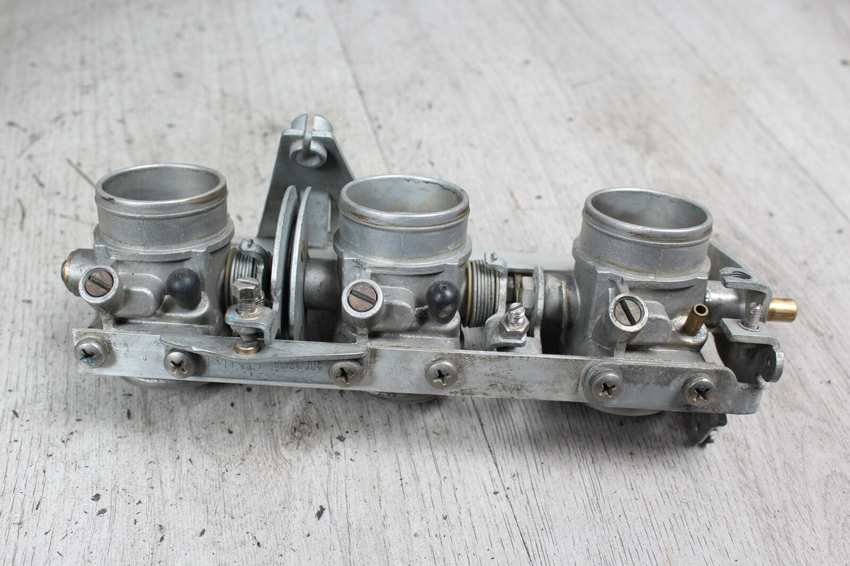
I'm probably going down this route mainly for the induction sound, the response and the looks. Topped with K&N filters (breathing in that super hot engine bay air....) with machined alloy covers. Hmmmmmmmm yummy.
However if I don't do itbs for some reason then my next choice will be to fabricate some neat looking runners that are fed from a single centre mounted plenum, in a sort of slight race car like finish. A single throttle body and a nice machined top to the plenum chamber. This would be the easiest and quickest route, with the stock inlet runners lending themselves to being modified to suit.
ECU I already have (Megasquirt 3 since you ask) can do fully sequential on six. This will give me the ability to tune for a really sweet idle, better off the mark acceleration at low revs and hopefully better economy.
The exhaust. Here's a pic of the stock headers attached in place. They need a tiny bit of chopping and moving about to clear the back of the engine mount area, plus they sit too low, below the sump.
.jpg)
.jpg)
I'm undecided about mucking about with the headers themselves for what would probably be small gains. I wouldn't want to go any larger than 28mm od on the tubes and from my googling so far it's not a common size for stainless or mildsteel bends. I would love to have a person who is super well qualified and really experienced (which is more important really) about such things as exhaust airspeed and the effects the primaries have. Someone who does this for a living. But otherwise I'll keeping trawling through all the various opinions that google offers from men in pubs and their dogs, stack all the offers and snippets of info up an a big pile and select the mean average.
With a hint of gut instinct weighed heavily on by how much I can be arsed.
So far it seems that great exhaust sounds can and are to be had from these engines by mucking about with everything past the primaries. I suspect the gas leaves these little pipes with sod all resistance and Honda was happy with the airspeeds they got because if not it would have been very easy for them to have increased the size of them with no real other issues.
But they didn't. So I'm probably going to concentrate more on the length of them, keeping the pipes as equal as I can an look more deeply into what happens afterwards.
I'm super keen to hear lots of sage exhaust advice from other men in pubs though - if only to give more my mean average pile more height.
Here's a head. Lovely little things. Nicely made. Very clean and simple. Brilliant hemi design. Not sure on the valve angles but I could picture it flowing nicely (based on the knowledge of my mildly edumacated mind about such technical enginy things, stuff gained from reading old cars and car conversion books etc)
I measured the valves. The inlet is a fairly decent 33mm thereabouts.
Exhaust 28mm
Not bad. Not bad at all really. I dunno if they have anything mildly flash like a 3 angle seat. I suspect not. Goldwings are a pay grade above such frilvolous race engine nonsense. But I think I do happen to have a valve grinding setup and some seat cutters amongst the engine reconditioning stuff I was given a year or so ago.
Anyway.. I won't get too excited because as far as maximum flow at stratospheric revs go it heads downhill from the valve sizes. Just look at the size of this inlet port...
25mm
Extravagance ! Not really much room to open it out either, nor risk mucking about with the port innards. Too risky.Now the other end of the equation.
Exhaust port is 28mm one way and 23 the other. I think its cast like that on purpose to aid the low engine speed air flow (these engines are all about torque... and I'll probably mention that several times as I go on, just as I take a sip of my finest scotch. Lets not mention those dirty words like bhp and redlines)
The exhaust headers are comical. But I shouldn't really laugh because I know full well that the technical boffins at Honda know a heck of a lot more than me about cylinder head flow and tuning engines to suit bikes that are made to cruise all day long for a lifespan in the vicinity of 1,000,000 miles.
But still. They are funny..
At first glance one might be fooled into thinking they are maybe 26- 28mm like the ports. But they step down to an internal diameter of 23mm. Outside measures ap at around 26mm.
The valkyrie items are not bigger from what I can gather. They just have a poncy bit of shiny chrome tube over them so they look bigger..and shiny.
So there we have it.
Plans thus far.
My intention is to start the induction side with some bmw k75 itbs, injectors mounted into custom flanges to suit. They are about 34mm thereabouts so hugely more than big enough. They are not perfect though and will involve a bit of tinkering because the K series of engines have port spacing at 75mm and the Goldwing ports are spaced at 90mm. But they are separate and things could be adapted I'm sure.
These ..
I'm probably going down this route mainly for the induction sound, the response and the looks. Topped with K&N filters (breathing in that super hot engine bay air....) with machined alloy covers. Hmmmmmmmm yummy.
However if I don't do itbs for some reason then my next choice will be to fabricate some neat looking runners that are fed from a single centre mounted plenum, in a sort of slight race car like finish. A single throttle body and a nice machined top to the plenum chamber. This would be the easiest and quickest route, with the stock inlet runners lending themselves to being modified to suit.
ECU I already have (Megasquirt 3 since you ask) can do fully sequential on six. This will give me the ability to tune for a really sweet idle, better off the mark acceleration at low revs and hopefully better economy.
The exhaust. Here's a pic of the stock headers attached in place. They need a tiny bit of chopping and moving about to clear the back of the engine mount area, plus they sit too low, below the sump.
I'm undecided about mucking about with the headers themselves for what would probably be small gains. I wouldn't want to go any larger than 28mm od on the tubes and from my googling so far it's not a common size for stainless or mildsteel bends. I would love to have a person who is super well qualified and really experienced (which is more important really) about such things as exhaust airspeed and the effects the primaries have. Someone who does this for a living. But otherwise I'll keeping trawling through all the various opinions that google offers from men in pubs and their dogs, stack all the offers and snippets of info up an a big pile and select the mean average.
With a hint of gut instinct weighed heavily on by how much I can be arsed.
So far it seems that great exhaust sounds can and are to be had from these engines by mucking about with everything past the primaries. I suspect the gas leaves these little pipes with sod all resistance and Honda was happy with the airspeeds they got because if not it would have been very easy for them to have increased the size of them with no real other issues.
But they didn't. So I'm probably going to concentrate more on the length of them, keeping the pipes as equal as I can an look more deeply into what happens afterwards.
I'm super keen to hear lots of sage exhaust advice from other men in pubs though - if only to give more my mean average pile more height.
06-16-2022, 05:20 PM
#39
Advanced
Thread Starter
So while I plan out what my induction and exhaust setup with consist of I thought it best to get the alternator sorted.
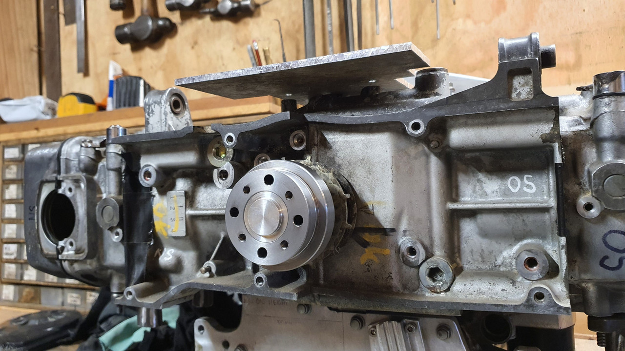
The goldwing engine originally had its alternator mounted off the back of the engine on a seperate casing now removed and driven via one of the many gears that resided within this casing between the engine and the clutch area. That area is now taken up by the bellhousing I have built and the alternator has to go on the front of the engine (which now the back ? of the engine as it sits in the imp..) and be driven off a crankshaft pulley that does not exist.
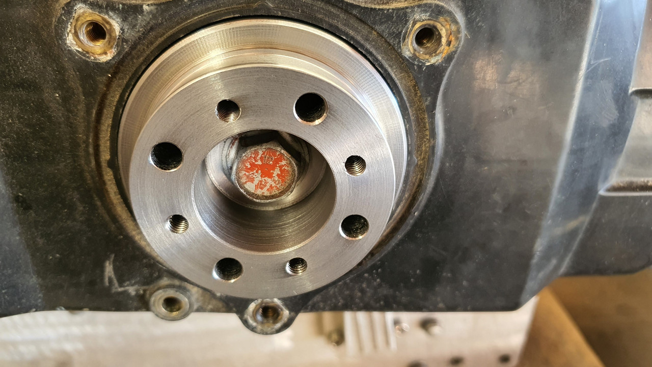
This is what it looks like ..
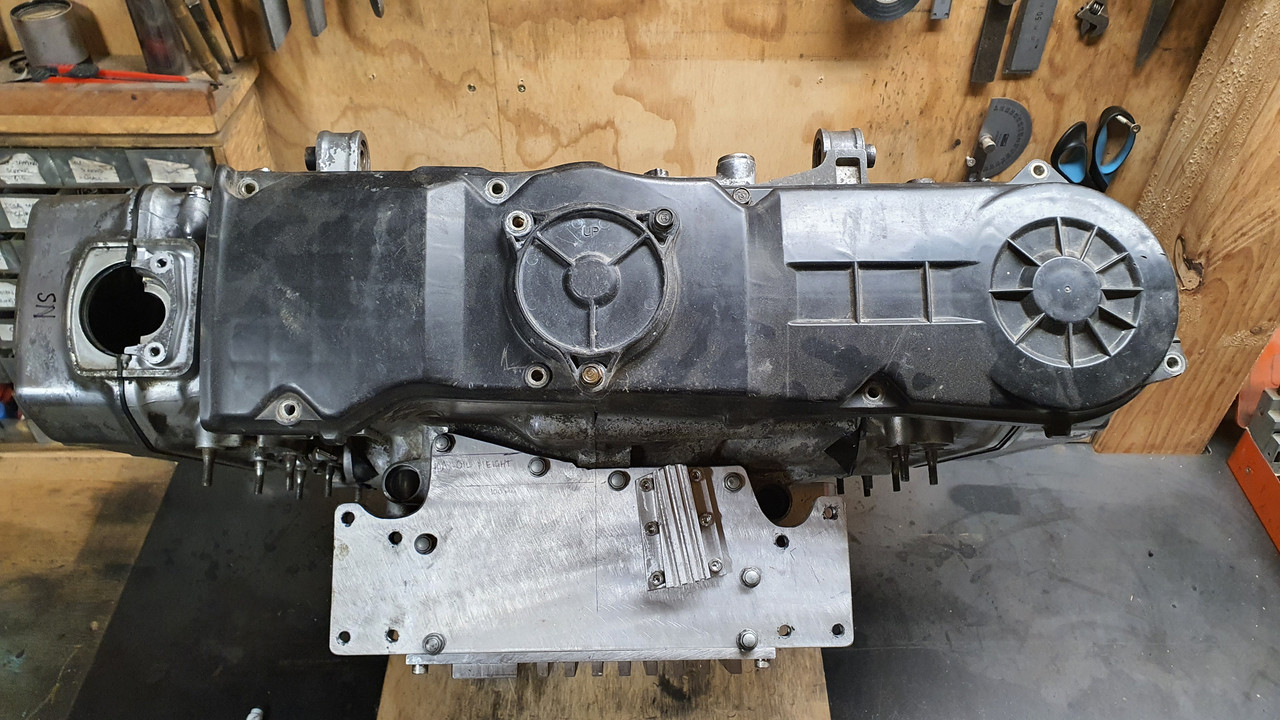
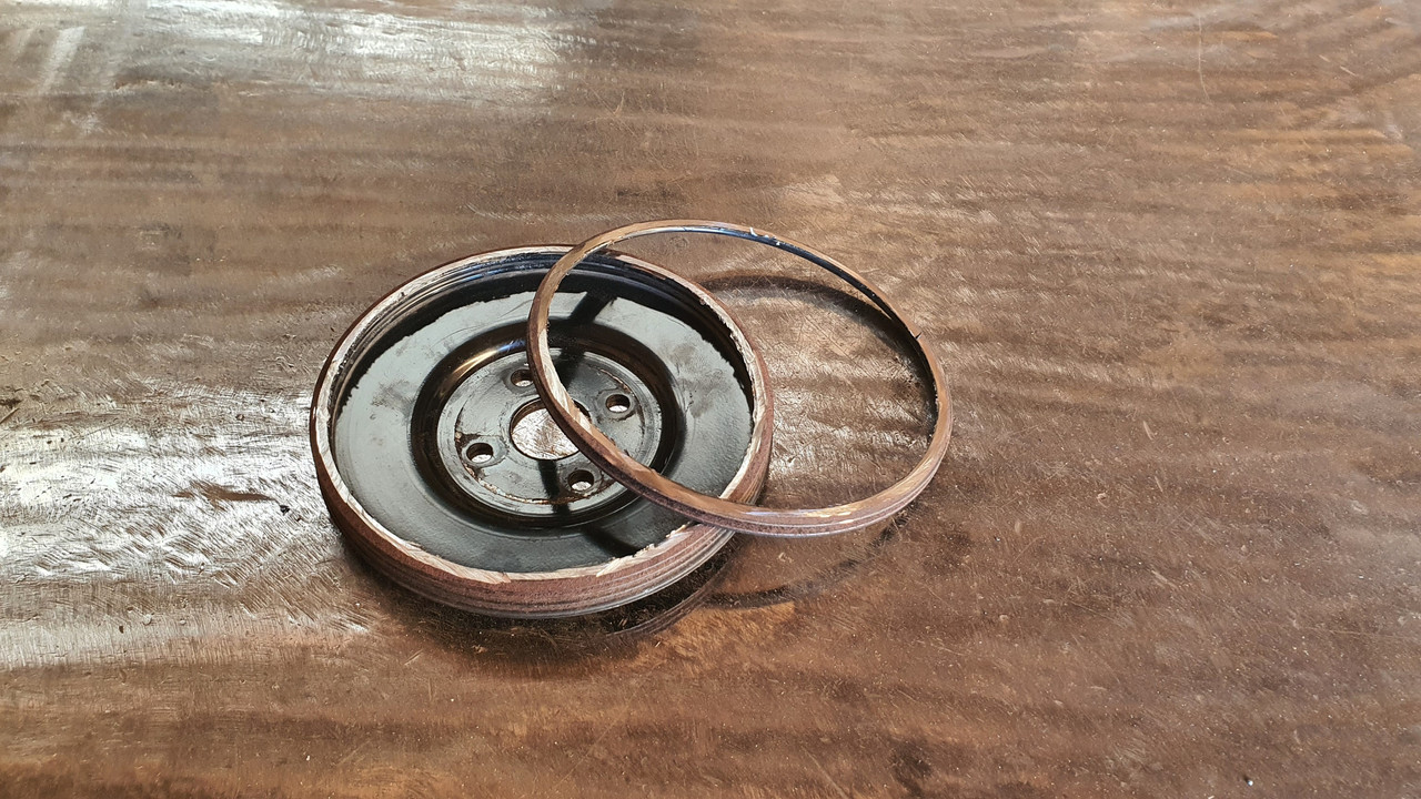
That little round cover hides the main cambelt drive pulleys and has a belt guide plate marked with various timing marks for setting up the ignition..

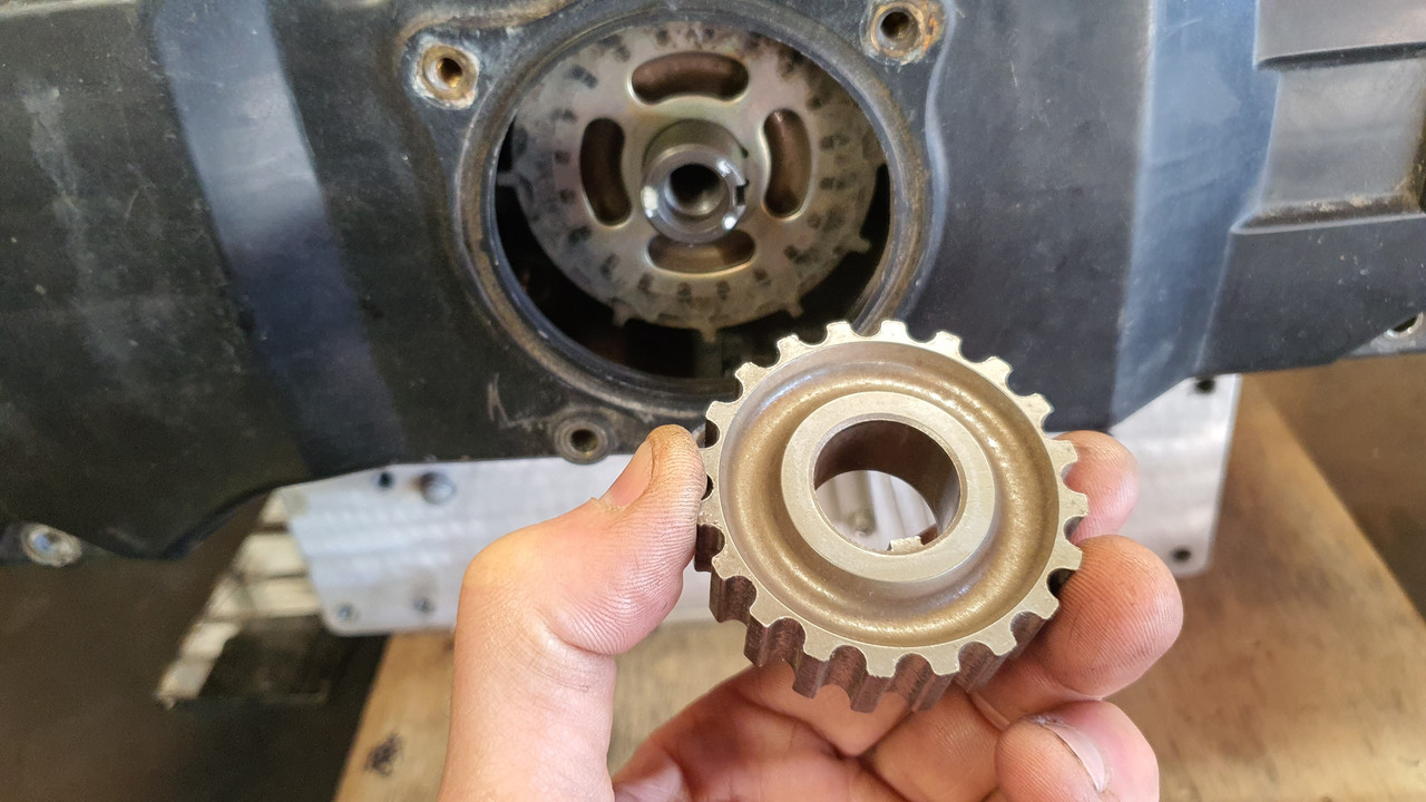
Under that pressed steel disc resides the first of the pulleys.
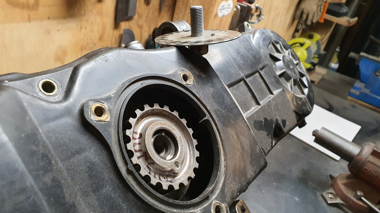
Sandwiched between the pulleys is a 12 tooth trigger wheel - handy for my planned engine management on a six. I'll replace it with a 36-1 wheel though.
So I need to machine up a few bits to allow the crank to run a mini v belt pulley and drive the Honda alternator which I had picked up at the local wreckers will sit about here...

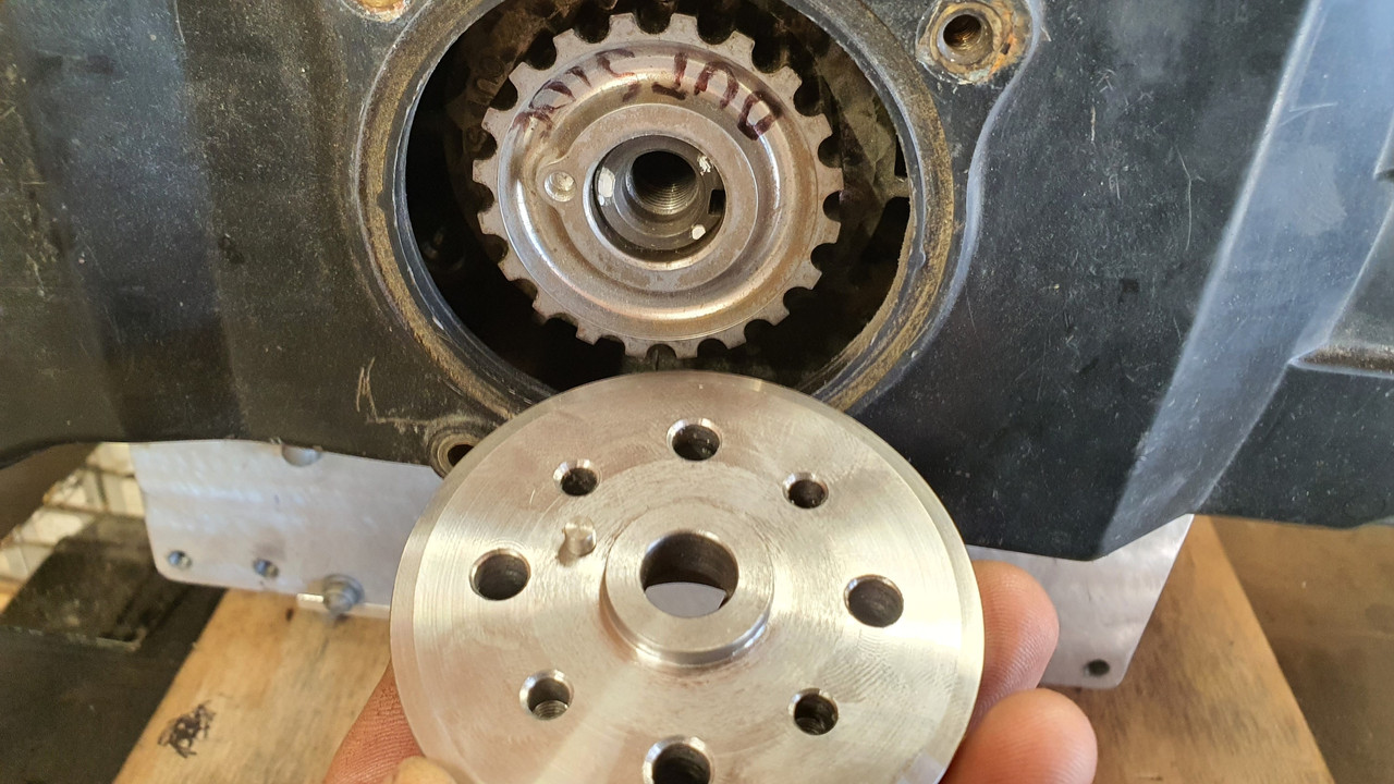
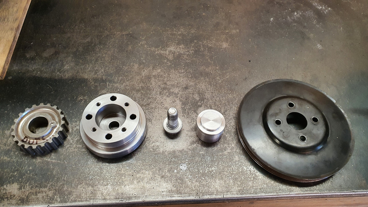
At another wreckers I found a pressed steel 5pk pulley from a power steering pump that was about the right diameter, had a flat mounting face and bolted in place with 4 little bolts. Ideal for my plan. I cut it down to suit a 3pk belt..
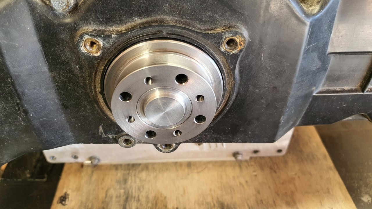
Then I popped a big lump of steel bar I luckily had left over from some other job into the lathe and machined up a hub with a locating extension on one side to match the inside of the cambelt pulley, of which which extends beyond the crankshaft nose by about 3mm. It drives , via a pin pushed into hub, off the hole in the cambelt pulley, which is there to locate the original timing plate..
The other side of this hub I bored out as far as I could whilst still allowing enough meat to bolt the pulley on.
This hub then bolts onto the crankshaft, eccentrically located by the camshaft pulley and held fast by the crankbolt..
Then I machined an alloy 'plug' that fits snug into the bored out hub, machined on the end to centrally locate the steel pulley, rather then rely on the bolts..

And all lined up...
So now I have a front drive pulley. Yay. Next up is making some sort of way to mount the alternator securely and not too ugly considering its going to be right there, centrally on view.
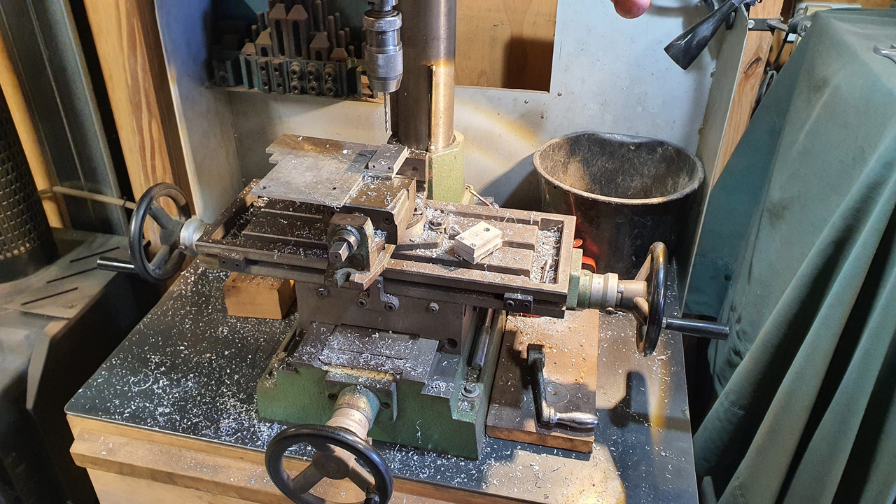
Starting the mount by making lots of little tiny bits of alloy to tread about the workshop with this tool...
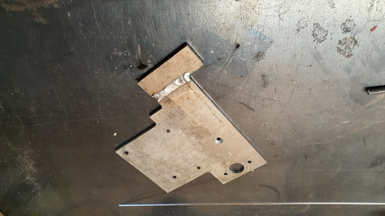
I cut some strong alloy plate and mounted it to the top of the engine using several of the conveniently placed cast in mounting points scattered about the place on top of the engine. Thanks Honda
I had to add a support on the front, easily bolted to the cambelt housing. Now I had a place that the alternator brackets could be bolted to. I just made it up as I went along and machined bits and pieces until I had what I was looking for. I wanted it to look a mix of between sort of factory and sort of 'race car'.
I had lots of fun making more alloy swarf..
Of course I cut my plate too narrow...
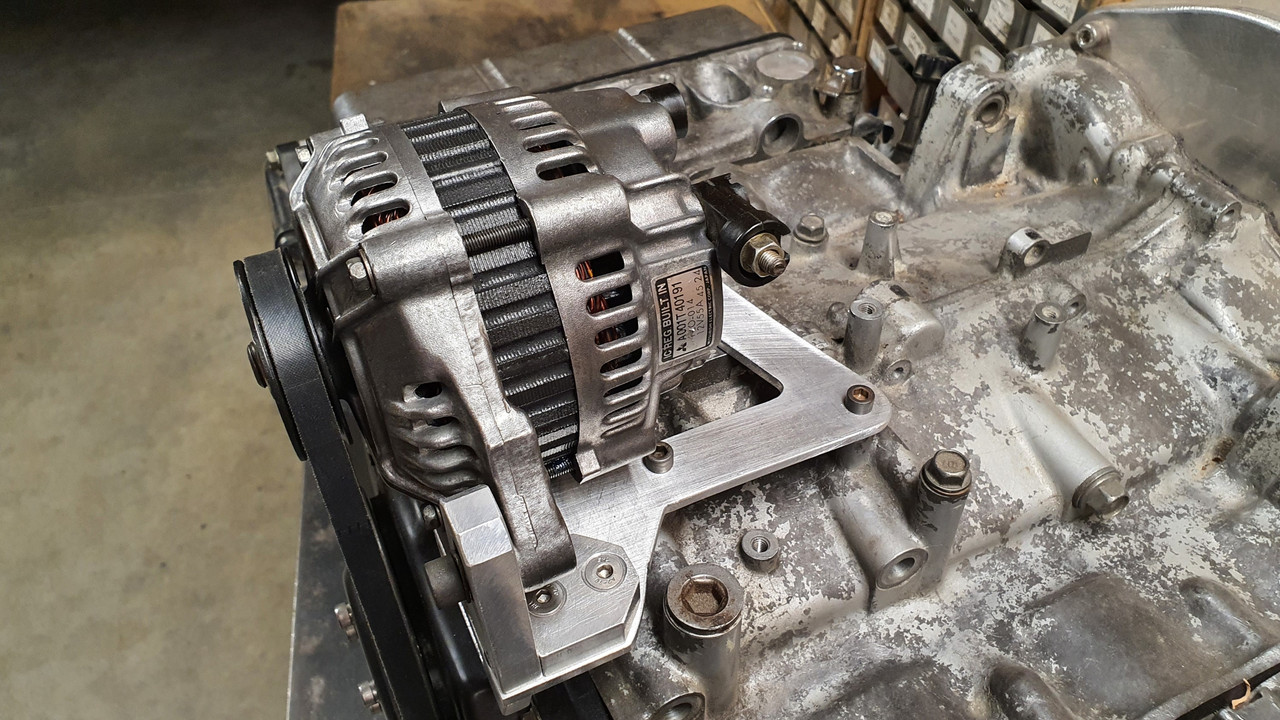
Eventually I ended up with all these bits to piece together...
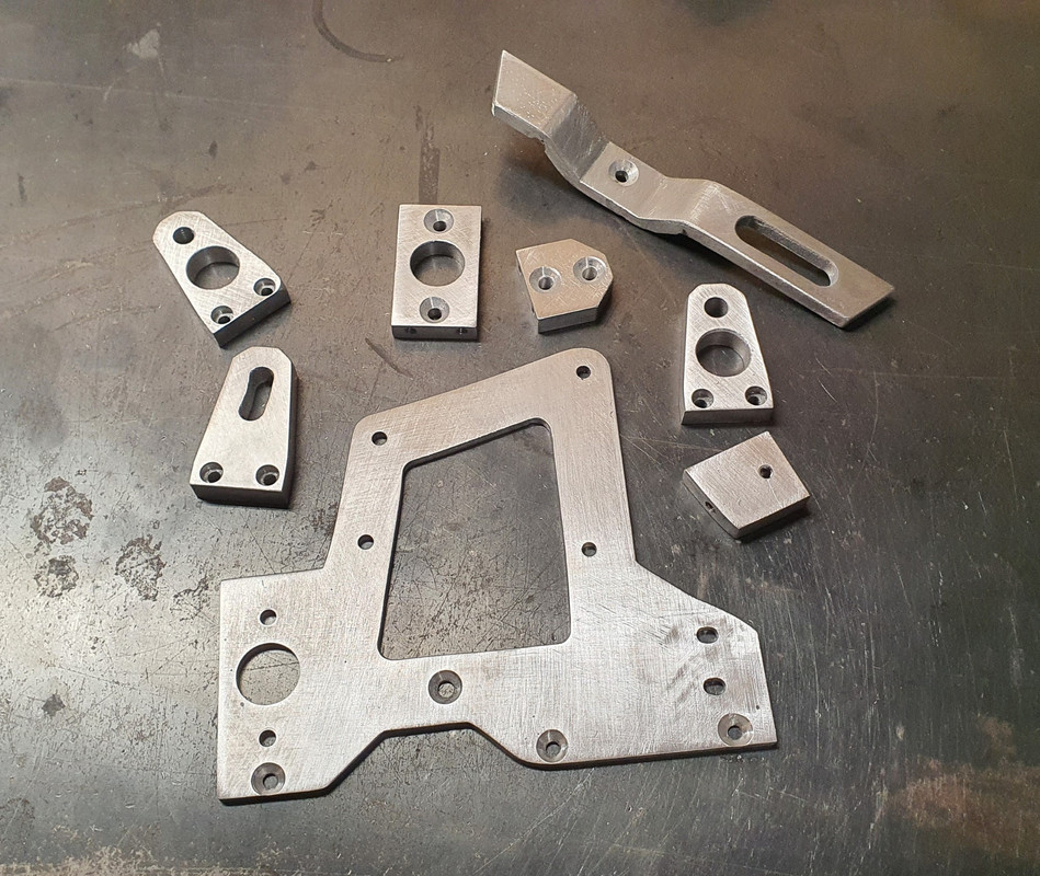
Together they made this..

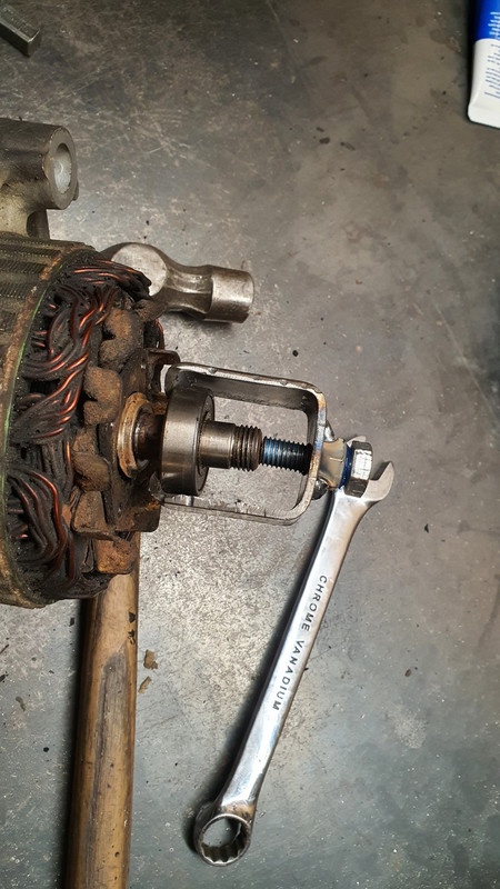
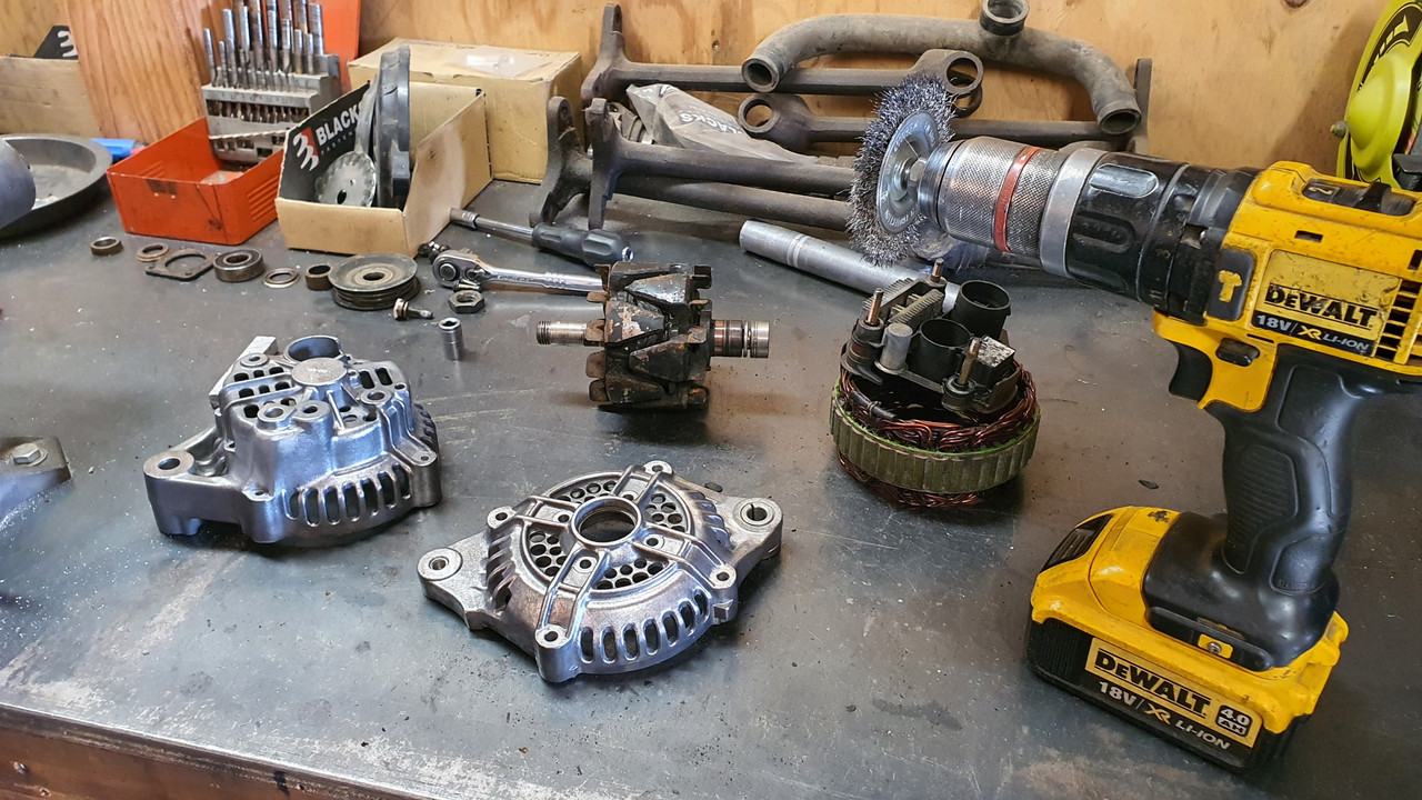
But before I plonked the alternator in place I had to clean it. It looked horrid and had obviously resided in a Honda of some ilk with some serious oil leaks. It was also a bit corroded and things didn't want to pull apart too easily. I made a bespoke little bearing puller..
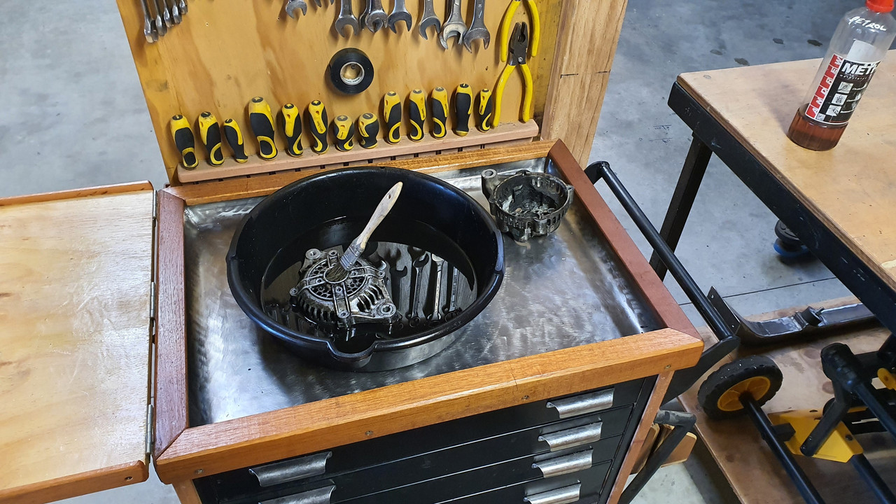
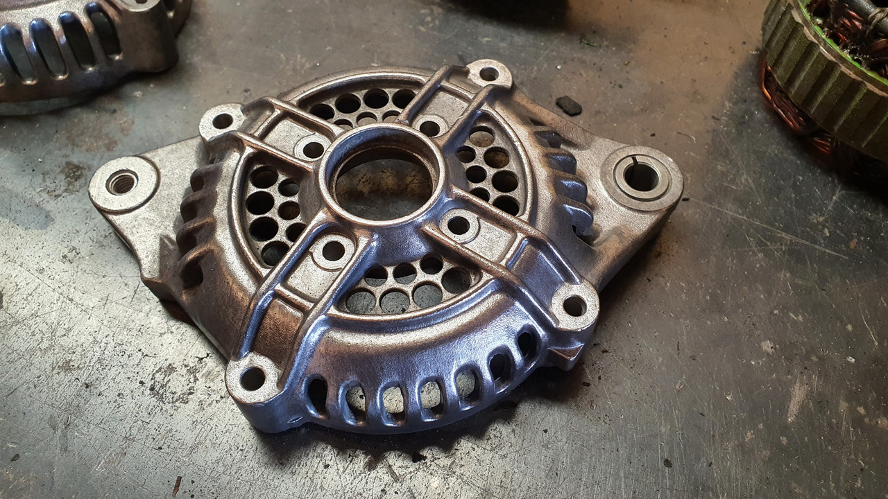
The filthy alloy castings came up nice with a petrol bath..
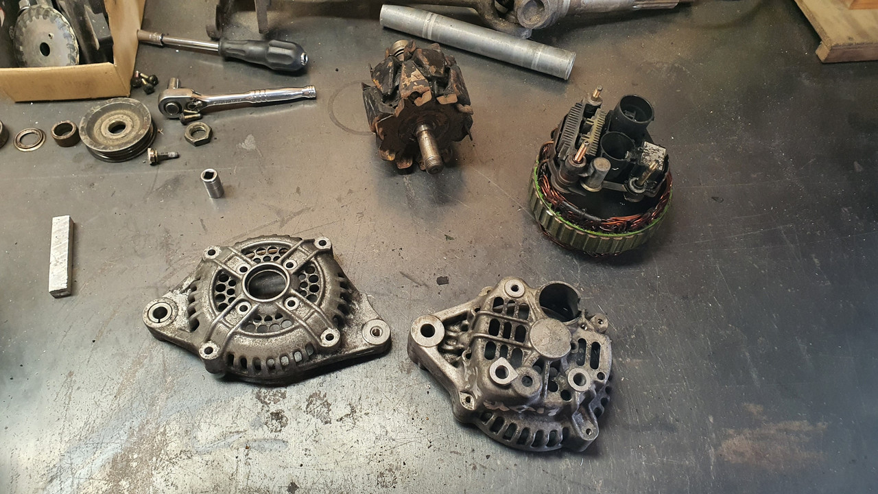
and even nicer with some wire brushing...
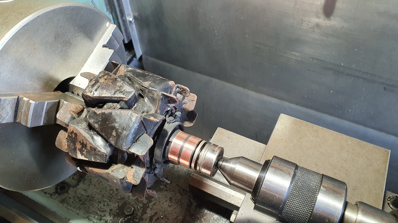
While it was apart I cleaned up the slip rings...
Painted the centre black. It will possibly be repainted in Imp blue at a later date, as a treat if the engine swap works out ok. Its just a look I quite like - call me 90s boy.
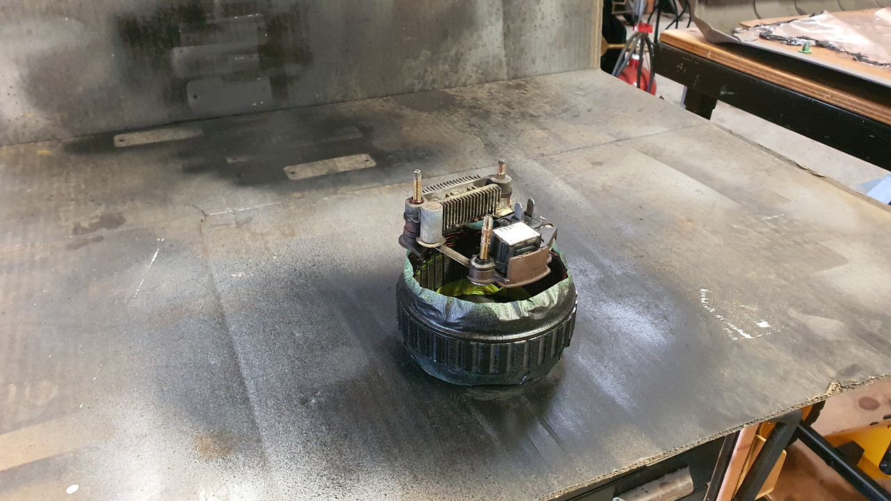
Bolted it all back together, complete with a new main bearing that I happened to have in stock (must be one of the most common bearings ever -35/15/10)
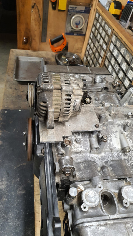
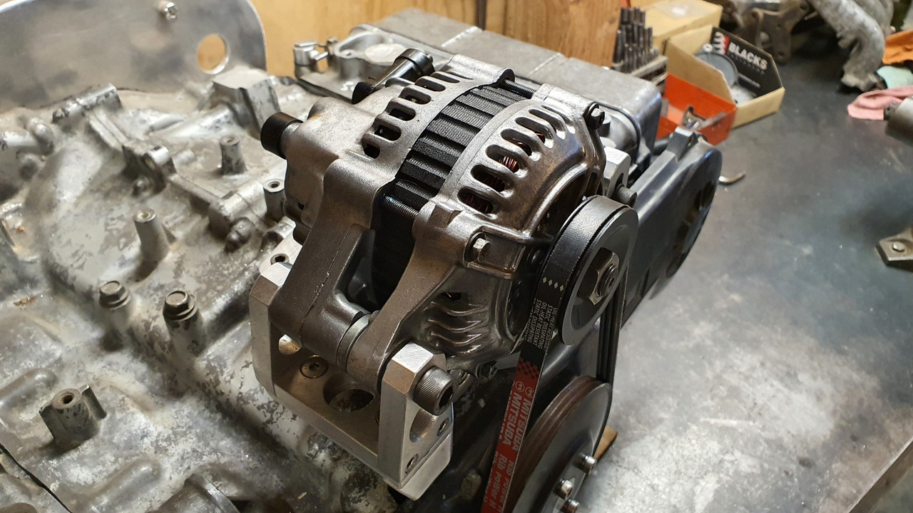
Then excitedly bolted it in place. My Honda goldwing now has a standard alternator mounted in a pretty normal fashion and it looks nice and neat...

With that sorted I can move onto making the cooling pipes and induction setup. I have still not fully made my mind up on what route I'll be taking here but I'll probably to bite the bullet and click buy now on a set of itbs so at least I have something to play with and go from there.
I need to find a set of suitable top feed injectors. Something around 200cc at a guess. The standard Honda goldwing 1800 items look like they'd be ok and pretty compact. I'll be making the mounting seats to suit, which I'll then weld in place on the stock intake runners. Fuel rail made to suit.
The goldwing engine originally had its alternator mounted off the back of the engine on a seperate casing now removed and driven via one of the many gears that resided within this casing between the engine and the clutch area. That area is now taken up by the bellhousing I have built and the alternator has to go on the front of the engine (which now the back ? of the engine as it sits in the imp..) and be driven off a crankshaft pulley that does not exist.
This is what it looks like ..
That little round cover hides the main cambelt drive pulleys and has a belt guide plate marked with various timing marks for setting up the ignition..
Under that pressed steel disc resides the first of the pulleys.
Sandwiched between the pulleys is a 12 tooth trigger wheel - handy for my planned engine management on a six. I'll replace it with a 36-1 wheel though.
So I need to machine up a few bits to allow the crank to run a mini v belt pulley and drive the Honda alternator which I had picked up at the local wreckers will sit about here...
At another wreckers I found a pressed steel 5pk pulley from a power steering pump that was about the right diameter, had a flat mounting face and bolted in place with 4 little bolts. Ideal for my plan. I cut it down to suit a 3pk belt..
Then I popped a big lump of steel bar I luckily had left over from some other job into the lathe and machined up a hub with a locating extension on one side to match the inside of the cambelt pulley, of which which extends beyond the crankshaft nose by about 3mm. It drives , via a pin pushed into hub, off the hole in the cambelt pulley, which is there to locate the original timing plate..
The other side of this hub I bored out as far as I could whilst still allowing enough meat to bolt the pulley on.
This hub then bolts onto the crankshaft, eccentrically located by the camshaft pulley and held fast by the crankbolt..
Then I machined an alloy 'plug' that fits snug into the bored out hub, machined on the end to centrally locate the steel pulley, rather then rely on the bolts..
And all lined up...
So now I have a front drive pulley. Yay. Next up is making some sort of way to mount the alternator securely and not too ugly considering its going to be right there, centrally on view.
Starting the mount by making lots of little tiny bits of alloy to tread about the workshop with this tool...
I cut some strong alloy plate and mounted it to the top of the engine using several of the conveniently placed cast in mounting points scattered about the place on top of the engine. Thanks Honda
I had to add a support on the front, easily bolted to the cambelt housing. Now I had a place that the alternator brackets could be bolted to. I just made it up as I went along and machined bits and pieces until I had what I was looking for. I wanted it to look a mix of between sort of factory and sort of 'race car'.
I had lots of fun making more alloy swarf..
Of course I cut my plate too narrow...
Eventually I ended up with all these bits to piece together...
Together they made this..
But before I plonked the alternator in place I had to clean it. It looked horrid and had obviously resided in a Honda of some ilk with some serious oil leaks. It was also a bit corroded and things didn't want to pull apart too easily. I made a bespoke little bearing puller..
The filthy alloy castings came up nice with a petrol bath..
and even nicer with some wire brushing...
While it was apart I cleaned up the slip rings...
Painted the centre black. It will possibly be repainted in Imp blue at a later date, as a treat if the engine swap works out ok. Its just a look I quite like - call me 90s boy.
Bolted it all back together, complete with a new main bearing that I happened to have in stock (must be one of the most common bearings ever -35/15/10)
Then excitedly bolted it in place. My Honda goldwing now has a standard alternator mounted in a pretty normal fashion and it looks nice and neat...
With that sorted I can move onto making the cooling pipes and induction setup. I have still not fully made my mind up on what route I'll be taking here but I'll probably to bite the bullet and click buy now on a set of itbs so at least I have something to play with and go from there.
I need to find a set of suitable top feed injectors. Something around 200cc at a guess. The standard Honda goldwing 1800 items look like they'd be ok and pretty compact. I'll be making the mounting seats to suit, which I'll then weld in place on the stock intake runners. Fuel rail made to suit.
The following users liked this post:
LimeyBoy (05-29-2023)
06-17-2022, 04:47 AM
#41
Advanced
Thread Starter
 06-17-2022, 11:24 AM
#42
Three Wheelin'
yeah, the alternator placement is key to the overall theme. nice work on all those parts to mount it.
and agreed, it looks great with the intake above!
and agreed, it looks great with the intake above!
06-17-2022, 07:55 PM
#43
Advanced
Thread Starter
They dont look too bad at all do they- especially given the cruddiness. I'm still not set on the induction setup yet so I'm looking into designing some sort of central plenum using these runners and make a rear mounted throttle body with a cold air feed from a remote air filter. Its either that or ITBs - but the room I have for itbs will mean thin filters, hot air and short runners which will absorb some of the low speed smoothness and torque these goldwing engines are renowned for.
Whatever I end up building has to look neat and tidy and remain somewhat symetrical.
Whatever I end up building has to look neat and tidy and remain somewhat symetrical.


The following users liked this post:
yoeddynz (06-18-2022)