
El-Wire, Alternative to OEM and LED Bulbs for Gauges
 04-16-2009, 03:16 PM
#1
Racer
Thread Starter
First off, I want to thank LukeSportsman for bringing this to our attention and SpeedRacerIndy for being the Beta Tester.
Tools Needed/Recommended:
1. Small Flat/Standard Screw Driver (De-Crimper)
2. Mini Socket Extension or Hand Driver (Crimper)
3. Soldering Iron
4. Heat Gun
5. Wire Tags (to keep all wires in order, there are over 2 dozen)
6. Co2 Air Duster
7. Double Sided Tape (New, check your tape before you use them, I found mine was yellowed and old, apparently my sealed zip lock back had a hole in it)
8. Razor to cut and prep the El-Wires or Purchase an El-Wire Splicer
WIIT (While I'm In There)
Flourescent Orange Acrylic Paint
Gauge Disassembly/Prep:
DISCONNECT THE BATTERY, but you knew that
1. I doubled check to insure I had proper access from the trunk. Verified. It measured roughly 3' to the Fuse Box.
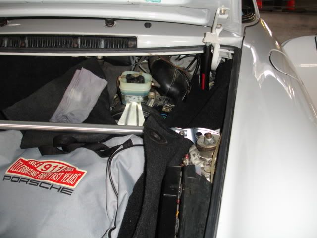
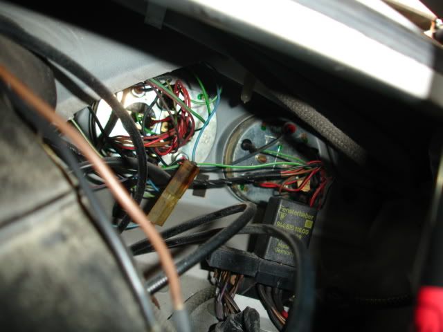
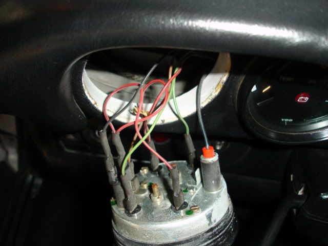
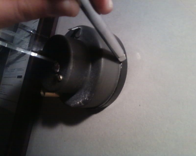
2. Pulled out the Fuel/Oil Level Gauge first to verify secondary unused Ground (this is where you connect the positive lead from the El-Wire Inverter) then used the port to help push out the remaining Gauges by putting my hand through the hole and behind the Gauges. Yes, I labelled all connections and wires. The Male Spade below the OEM port is unused Ground.
Caution, the Oil Temp/Druck does not have that much slack so take care not to pull too hard as not to disturb the wiring harness assembly.
3. Located the bundled 8 Gauge Light Bulb (Black/Blue) Wires and Splitter at the Tach Hole. Note the splitter is a Female Spade (this is where your connect the negative lead, remember, we are a negative ground 12 volt system).
Tools Needed/Recommended:
1. Small Flat/Standard Screw Driver (De-Crimper)
2. Mini Socket Extension or Hand Driver (Crimper)
3. Soldering Iron
4. Heat Gun
5. Wire Tags (to keep all wires in order, there are over 2 dozen)
6. Co2 Air Duster
7. Double Sided Tape (New, check your tape before you use them, I found mine was yellowed and old, apparently my sealed zip lock back had a hole in it)
8. Razor to cut and prep the El-Wires or Purchase an El-Wire Splicer
WIIT (While I'm In There)
Flourescent Orange Acrylic Paint
Gauge Disassembly/Prep:
DISCONNECT THE BATTERY, but you knew that
1. I doubled check to insure I had proper access from the trunk. Verified. It measured roughly 3' to the Fuse Box.
2. Pulled out the Fuel/Oil Level Gauge first to verify secondary unused Ground (this is where you connect the positive lead from the El-Wire Inverter) then used the port to help push out the remaining Gauges by putting my hand through the hole and behind the Gauges. Yes, I labelled all connections and wires. The Male Spade below the OEM port is unused Ground.
Caution, the Oil Temp/Druck does not have that much slack so take care not to pull too hard as not to disturb the wiring harness assembly.
3. Located the bundled 8 Gauge Light Bulb (Black/Blue) Wires and Splitter at the Tach Hole. Note the splitter is a Female Spade (this is where your connect the negative lead, remember, we are a negative ground 12 volt system).
continued...
 04-16-2009, 03:17 PM
#2
Racer
Thread Starter
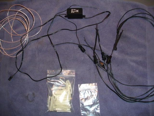
EL-Wire Preparation:
Items Needed:
1. 5.5 Feet of 2.2 MM WHITE El-Wire (raw) but they only sell in 1 foot increments
2. 5-Way Splitter
3. 5 Female El-Wire Connectors
4. 5 End Caps
5. 8-13' Inverter (to accomodate the length of all wires connected in total)
6. 1-Male and 1-Female 1/4" Spade
7. Heat Shrink Wrap (assorted sizes, I used Clear and Black)
8. Stereo Wire to equal the length of the power/ground leads of the Inverter(or similar gauge, the Inverter I ordered had a length of 3' on the leads and 10" on the El-Wire connection side, so I measured off as needed and spliced)
Gauges:
1. Used the small standard screw driver to slowly and carefully de-crimp the rim's edge from behind of the Gauge. The tin was actually pretty soft. I made a final pry which deformed the ring but no worries it goes back with no deformation.
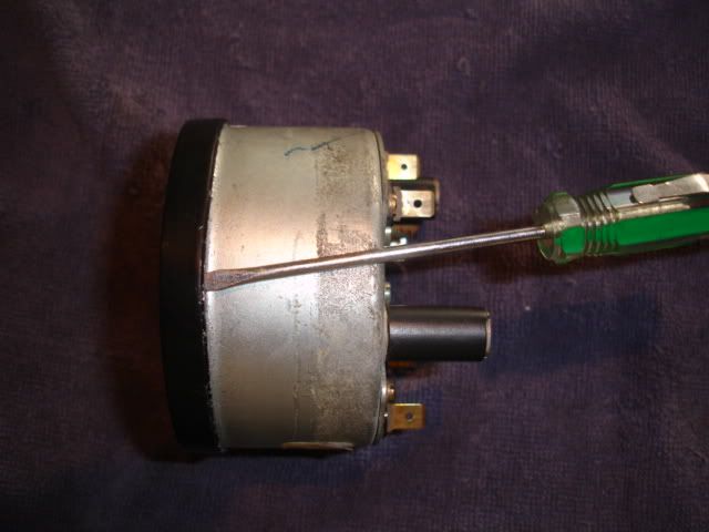
Note: The outer ring comes in two parts outer and inner then the Glass/Lens. Behind the glass is another inner rim then the Gauge face. The Rim behind the glass will help hold the El-Wire in place in case the tape loses it's adhesion. The El-Wire were a snug fit.
2. I used a pencil to draw a line where I want the El-Wire to be mounted. I used the face of the Gauge as a guide.
3. Placed cut 1/4" wide double sided tape generously along the marked line. (ordered their mounts but they are too week to stay on the inside of the housing.)
4. Fed the El-Wire through the existing OEM Light Bulb port and then I attached to the tape.
5. Tested the wire before I closed it up. I used my LED Wand Light's 12v charger.
6. To RE-CRIMP, I used the mini socket extension due to it's smooth semi-curved tip. I glided it over the edge the pressed down in increments. It worked great, no movement at all. No obvious de-crimping spots.
7. For the Speedometer, SpeedracerIndy and I were concerned the El-Wire would not eluminate enough to get to the numbers. As you can see I decided to start the illumination from the port holes to help fill in the housing but for extra measure I routed the El-Wire behind the face over the top edge of the odometer and then routed down and below the tripometer. It so happens the space between the Face and Mount for the meters are a perfect size to slip the El-Wire into. There are also pilars that keep the El-Wire from droping on to or up to the meters. Sorry no Pics, I was not sure if it would work and when it did I was too excited and sealed it before taking photos.
DO NOT Make Sharp Bends on the El-Wire, they will short out if exposed to constant bending. Ask SpeedRacerIndy.
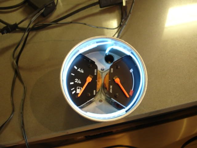
WIIT, I repainted the needles and marks back to Flourescent Orange. They look great and this El-Wire brings out the flourescent effect much better then the OEM bulbs. I also used my spare LEDs to replace the "BRIGHTS" and "Running" Light Indicators.
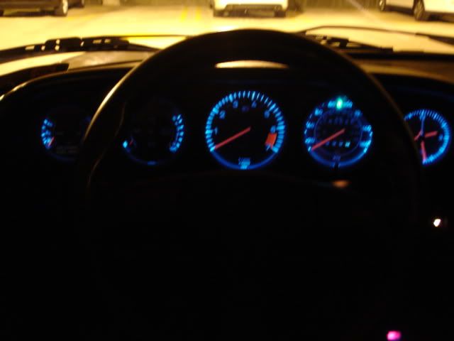
Here is the final outcome. It evenly distributes light on the Gauges and it is not too bright and YES the dimmer does work.
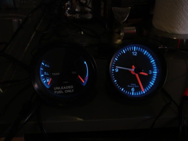

Remember you want to remotely locate the Invertor due to it's whining sound it emmits. This is why I chose the 8-13 foot Inverter.
Hope this helps. Sorry for any typos.
If I had to do it again, to save time, I would order 4 1 foot & a 2 foot El-Wire with connectors pre-attached. Trim as needed. I almost went blind trying to find those damn ground wires (they were literaly thin as hair, very brittle) on that 2.2MM El-Wire to solder.
Cost $25
Time 6 hours
Did not cut any OEM Wiring
Modern Looking Even Lit Gauges, PRICELESS
Items Needed:
1. 5.5 Feet of 2.2 MM WHITE El-Wire (raw) but they only sell in 1 foot increments
2. 5-Way Splitter
3. 5 Female El-Wire Connectors
4. 5 End Caps
5. 8-13' Inverter (to accomodate the length of all wires connected in total)
6. 1-Male and 1-Female 1/4" Spade
7. Heat Shrink Wrap (assorted sizes, I used Clear and Black)
8. Stereo Wire to equal the length of the power/ground leads of the Inverter(or similar gauge, the Inverter I ordered had a length of 3' on the leads and 10" on the El-Wire connection side, so I measured off as needed and spliced)
Gauges:
1. Used the small standard screw driver to slowly and carefully de-crimp the rim's edge from behind of the Gauge. The tin was actually pretty soft. I made a final pry which deformed the ring but no worries it goes back with no deformation.
Note: The outer ring comes in two parts outer and inner then the Glass/Lens. Behind the glass is another inner rim then the Gauge face. The Rim behind the glass will help hold the El-Wire in place in case the tape loses it's adhesion. The El-Wire were a snug fit.
2. I used a pencil to draw a line where I want the El-Wire to be mounted. I used the face of the Gauge as a guide.
3. Placed cut 1/4" wide double sided tape generously along the marked line. (ordered their mounts but they are too week to stay on the inside of the housing.)
4. Fed the El-Wire through the existing OEM Light Bulb port and then I attached to the tape.
5. Tested the wire before I closed it up. I used my LED Wand Light's 12v charger.
6. To RE-CRIMP, I used the mini socket extension due to it's smooth semi-curved tip. I glided it over the edge the pressed down in increments. It worked great, no movement at all. No obvious de-crimping spots.
7. For the Speedometer, SpeedracerIndy and I were concerned the El-Wire would not eluminate enough to get to the numbers. As you can see I decided to start the illumination from the port holes to help fill in the housing but for extra measure I routed the El-Wire behind the face over the top edge of the odometer and then routed down and below the tripometer. It so happens the space between the Face and Mount for the meters are a perfect size to slip the El-Wire into. There are also pilars that keep the El-Wire from droping on to or up to the meters. Sorry no Pics, I was not sure if it would work and when it did I was too excited and sealed it before taking photos.
DO NOT Make Sharp Bends on the El-Wire, they will short out if exposed to constant bending. Ask SpeedRacerIndy.
WIIT, I repainted the needles and marks back to Flourescent Orange. They look great and this El-Wire brings out the flourescent effect much better then the OEM bulbs. I also used my spare LEDs to replace the "BRIGHTS" and "Running" Light Indicators.
Here is the final outcome. It evenly distributes light on the Gauges and it is not too bright and YES the dimmer does work.
Remember you want to remotely locate the Invertor due to it's whining sound it emmits. This is why I chose the 8-13 foot Inverter.
Hope this helps. Sorry for any typos.
If I had to do it again, to save time, I would order 4 1 foot & a 2 foot El-Wire with connectors pre-attached. Trim as needed. I almost went blind trying to find those damn ground wires (they were literaly thin as hair, very brittle) on that 2.2MM El-Wire to solder.
Cost $25
Time 6 hours
Did not cut any OEM Wiring
Modern Looking Even Lit Gauges, PRICELESS
04-16-2009, 06:37 PM
#3
I haddah Google dat
Rennlist Member
Rennlist Member
Like everyone else, I think I'm still reading and digesting this info.
You said the total cost is only $25? I still want to pull out a few of my gauges to evaluate how capabable I would be to do this. The crimp on the gauges is what worries me. But I think my tach has been uncrimped before, so I guess it's not too hard. What did you use to paint the pointers while you're in there? Did you also re-paint the tach redline? How hard was that to do?
Draco, very thorough write up! This should be submitted as a tech article
04-16-2009, 06:48 PM
#4
Instructor
Join Date: Sep 2007
Location: DFW
Posts: 212
Likes: 0
Received 0 Likes
on
0 Posts
Nice job and write up!
since EL does not like being bent back and forth I would also suggest tying down the ends just before and after the EL itself so vibrations do not vibrate it back and forth and short out. Also, the inverter needs to be somewhere where it gets enough air circulation to keep it cool.
since EL does not like being bent back and forth I would also suggest tying down the ends just before and after the EL itself so vibrations do not vibrate it back and forth and short out. Also, the inverter needs to be somewhere where it gets enough air circulation to keep it cool.
04-16-2009, 07:27 PM
#6
Racer
Thread Starter
Hey Rusnak, Thanks, it was worth it:
Yeap $25. I actually over bought parts but I roughly calculated the actual parts used.
Don't worry about the crimp on the gauges, just be patient and maticulous they are actually quite soft yet durable.
Paint: I used Acrylic Flourescnet Orange from a Art Supply store and a fine angular tipped brush. The Sales person told me over time it will fade again, he recommended getting UV protected glass, ( OK )
Yes, I re-painted all the Needles and Tach Redline, Oil Too Hot Indicator. Odd Oil Level is a Standard Red, did not touch that, color was good. EASY AS PIE
No the last two was to show they all worked before install. But Yes indeed, unlike the LEDs the OEM dimmer function works as designed.
Inverter, I placed mine right behind the Fuse Box and on the fender. Just make certain you keep it out of the cabin. It does make a faint whirling/wining sound
Hey NoSub:
Actually, if you look at the side of the gauges, there is a 2-2.5MM gap. When you place the inner ring behind the glass it fits snuggly there. It will not move, the doubled sided tape is for extra measure.
You are absolutely correct the Luminescent Wires do not like being bent back and forth on a sharp 90 degree angle. It will snap the inner fine filament wire and cause a short. It also recommended to use end caps to terminate any exposed wiring.
The inverter does get warm, after an hour of bench testing it, I was still able to handle it.
During the Day in a covered Parking Lot
Off

On
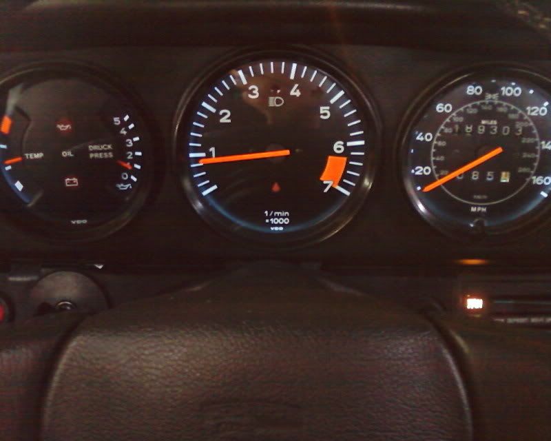
My previous LEDs were not visible during the day or twilight at all.
Yeap $25. I actually over bought parts but I roughly calculated the actual parts used.
Don't worry about the crimp on the gauges, just be patient and maticulous they are actually quite soft yet durable.
Paint: I used Acrylic Flourescnet Orange from a Art Supply store and a fine angular tipped brush. The Sales person told me over time it will fade again, he recommended getting UV protected glass, ( OK
)Yes, I re-painted all the Needles and Tach Redline, Oil Too Hot Indicator. Odd Oil Level is a Standard Red, did not touch that, color was good. EASY AS PIE
No the last two was to show they all worked before install. But Yes indeed, unlike the LEDs the OEM dimmer function works as designed.
Inverter, I placed mine right behind the Fuse Box and on the fender. Just make certain you keep it out of the cabin. It does make a faint whirling/wining sound
Hey NoSub:
Actually, if you look at the side of the gauges, there is a 2-2.5MM gap. When you place the inner ring behind the glass it fits snuggly there. It will not move, the doubled sided tape is for extra measure.
You are absolutely correct the Luminescent Wires do not like being bent back and forth on a sharp 90 degree angle. It will snap the inner fine filament wire and cause a short. It also recommended to use end caps to terminate any exposed wiring.
The inverter does get warm, after an hour of bench testing it, I was still able to handle it.
During the Day in a covered Parking Lot
Off
On
My previous LEDs were not visible during the day or twilight at all.
Last edited by DRACO A5OG; 04-16-2009 at 08:24 PM.
Trending Topics
04-17-2009, 01:47 PM
#10
I haddah Google dat
Rennlist Member
Rennlist Member
I have the LED "bulbs" and I don't necessarily feel that they are too ricer. I would say that the biggest benefit is better color rendition. But Draco's setup offers that, plus better illumination.
In my opinion, those stock bulbs were offered up to the Porsche gods as sacrifice.
In my opinion, those stock bulbs were offered up to the Porsche gods as sacrifice.
04-17-2009, 03:39 PM
#11
Racer
Thread Starter
Hey Ron,
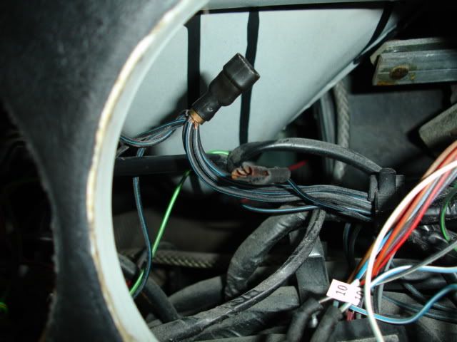
No the OEM bulbs are no longer used infact have been disconnected at the OEM splitter as in th elast pic of the first post.
Here is another pic at night showing the comparison to the LCD display of my Stereo:
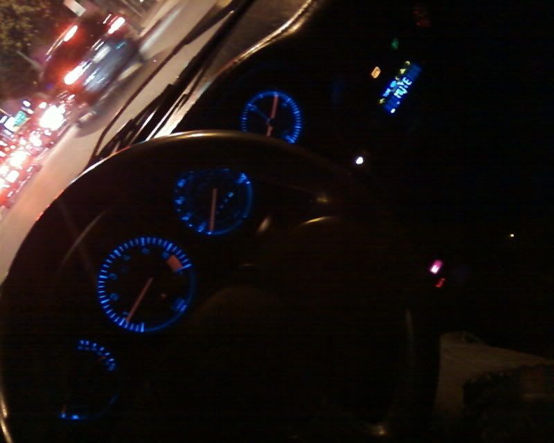
For technial Specs i.e. amps go to www.thatscoolwire.com. this stuff only draws 0.051 amps
No the OEM bulbs are no longer used infact have been disconnected at the OEM splitter as in th elast pic of the first post.
Here is another pic at night showing the comparison to the LCD display of my Stereo:
For technial Specs i.e. amps go to www.thatscoolwire.com. this stuff only draws 0.051 amps
04-18-2009, 01:36 AM
#13
Racer
Thread Starter
Thanks, I'm really pleased on how they turned out, much much better than the LED's, the glow of the orange is pretty sweet too. 
So if you guys are interested here is their website: www.thatscoolwire.com. Absolutely No Affiliation.
So if you guys are interested here is their website: www.thatscoolwire.com. Absolutely No Affiliation.
04-18-2009, 06:10 AM
#14
Burning Brakes

Join Date: Nov 2005
Location: CA
Posts: 798
Likes: 0
Received 0 Likes
on
0 Posts
yeah, better than LED because the light are even out everywhere, no spoted. If no bulbs now, then you can run wires through the bulb's holes huh, no drilling required right?
Another thought, your gauges now look very cheesy and ricy. I don't like them but if you want to go back to stock look I can help to exchange our gauges
Another thought, your gauges now look very cheesy and ricy. I don't like them but if you want to go back to stock look I can help to exchange our gauges