When you click on links to various merchants on this site and make a purchase, this can result in this site earning a commission. Affiliate programs and affiliations include, but are not limited to, the eBay Partner Network.
16v into 85.5 woes, no spark, no tach bounce, need to go racing!
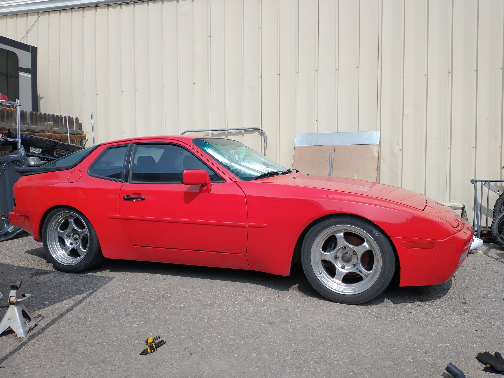
Ok, it's time for me to call on the masses for some help here. Finally got all the drivetrain and suspension into my autox/track 85.5 NA, including a 16v S motor/harness/ecu, rebuilt the motor with new rings, bearings, head job, etc.... I'm ready to start the motor but I'm not getting any spark, no tach bounce.
-I'm fairly confident the wiring for the ICM is correct but not 100%.
-Spent some time today doing some mild modification to the reference sensor bracket as it wasn't allowing a tight enough gap as it was- it's now properly gapped at the spec .8mm. According to the manual it should put out >3vAC while cranking- prior to appropriate gapping it was more like 2.2, now it's more like 9 volts? Not sure what's going on there and if that is an acceptable number. I do not have an oscilloscope to verify 100%. I also am not 100% sure that this particular sensor is in fact good since it came with the motor which I have never heard run, however it ohms out properly and seems to act appropriately.
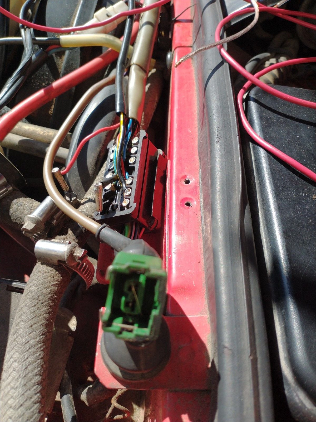
- I've wired the ICM as follows, and in a somewhat temporary manner to get the thing running prior to permanent wiring:
Black 12v wire is sharing key on 12v with the black coil wire, not sure if this is ok.
Green shielded signal wire is taking existing input into coil, coming from pin 1 on the 14 pin connector.
External wire around that wire is running to pin 14 on 14 pin connector.
The other green single wire is running to post on coil.
Brown is grounded to strut tower temporarily.
Again, this ICM came with the donor motor and I can't fully verify that it works as intended. I can't find a reasonable method of testing proper function. I'd rather not start throwing parts at it until I can confirm a particular part is suspect.
Questions:
-Does my ICM wiring seem correct?
-Would the ICM being wired incorrectly affect the "no tach bounce"? I was under the impression that if the ECU is seeing a signal from the reference sensor it would move the tach.
-Pin 12 on the 16v 14 pin connector side is supposedly supposed to have 12v at it- there is no pin on the car side plug. I've tried supplying 12v to it with no change, any input here?
-Also curious about pin 7 on the 16v side of the connector. No pin/wire there, some sources point to something needing to be plugged in there.
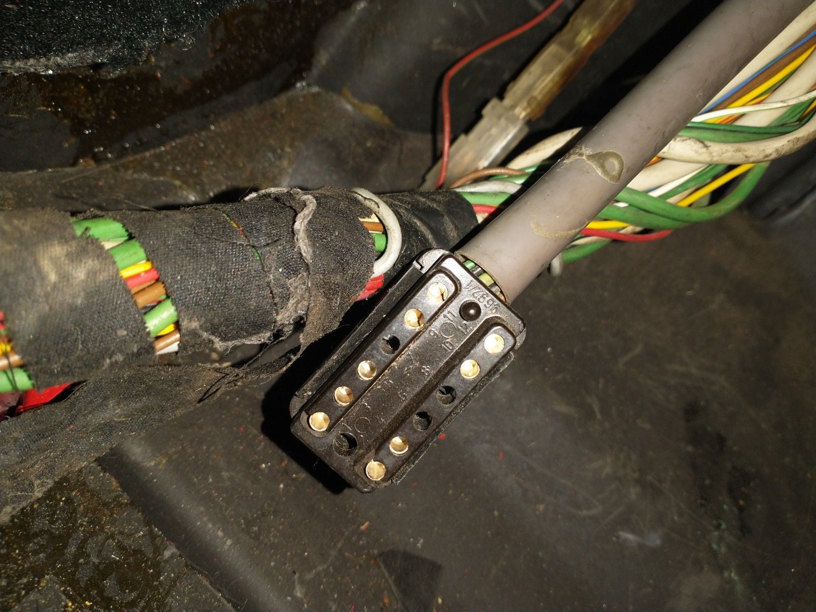
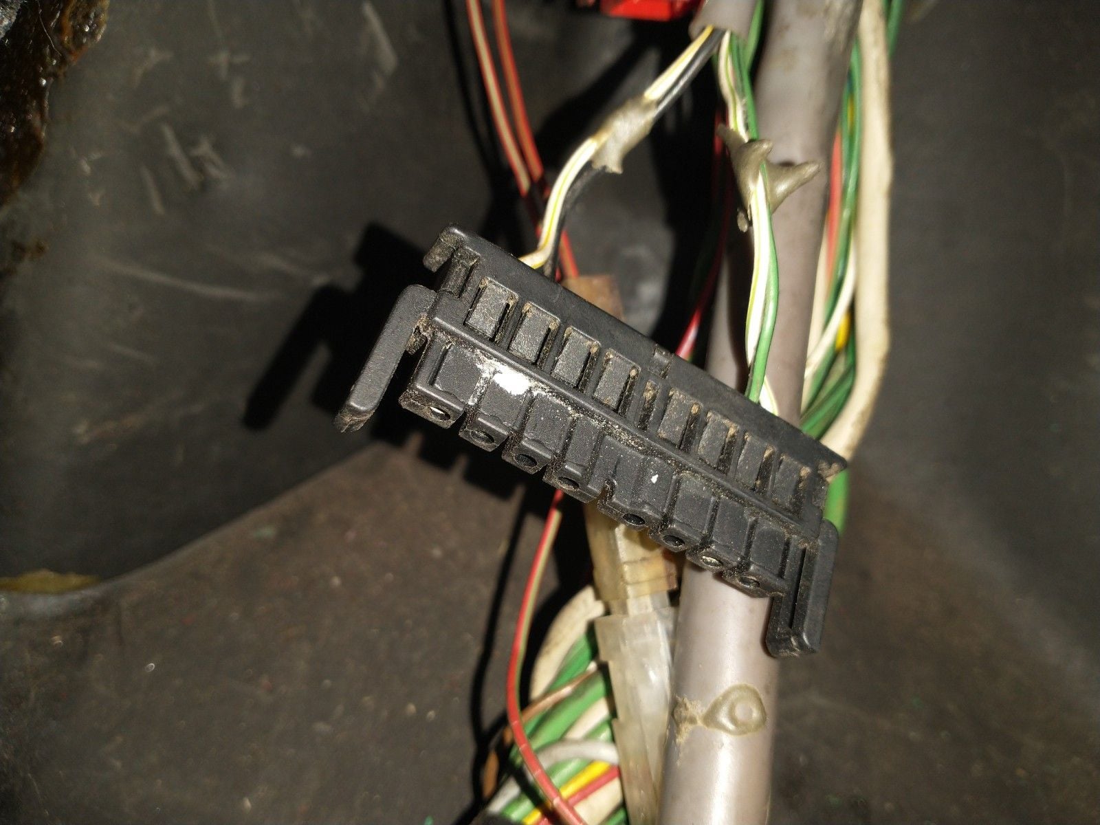
-There is a lonely green two prong plug near the 14 pin connector on the motor side of the harness, anyone know where this is supposed to connect, if anywhere? See attached picture.
I've gleaned a ton of info from existing threads on here, but after troubleshooting this for the last couple days my head is spinning with electrical diagnostics. I bet I've missed something simple and crucial but I can't tell exactly what.
I�m not positive from the pics but I think that green plug goes to the hall sensor on the back of the distributor cover.
Sorry, it's not easy to tell from that pic where that connector lives, it's near the driver side firewall and 14 pin connector. The hall sensor plug is good to go. I'll trace it out to the ECU today and see what it belongs to...
Alright does anyone have any comments on these lonely connectors? Trying to confirm that none need to be plugged in before I go any further stumbling around with my volt meter....
Thanks in advance. If anyone has a similar swap and doesn't mind contacting me that would be great! My head is starting to spin from troubleshooting electrical....
I apologize in advance for the terrible photos, my phone is a POS but hopefully you get the idea.
This green one is on the 16v engine harness right next to 14 pin connector that mates to body harness.
The rest are all in passenger footwell-
I know little two prong black one connects to barometric sensor. But what about the white 3 prong one?
I'm curious about the red 4 prong one that connected to 8v engine harness near ecu:
The bigger black 12 pin one I believe is for diagnostics and not necessary?
Do you have the Final Stage moved over from the S chassis and wired up correctly?
I'm fairly sure I do- but not 100%.
Brown is Grounded
Black running to switched 12v at coil
Small green running to coil
Large green running to pin 1 at 14 pin connector
Sheath of large green running to pin 14 at 14 pin connector
Do you know if there's a decent way to test the functionality of the ICM? (preferably without the need for an oscilloscope...) All of these electronic parts are 30+ years old and I'm not at all convinced they're still good.
I'm also curious if my hall effect sensor at the cam is good- I can't find a 100% confirmed answer as to what the resistance readings should be or if the motor should run with it unplugged...
Ok, so a little update/question- I've tested the living hell out of everything- I can get the coil to fire (through the ICM obviously) by sending a ground through pin 1 at the 14 pin connector. So the ICM is good, as is the coil.
It appears that the ECU is not sending the pulsed ground/ignition signal through pin 1 at all. My logic would say this either has to be a reference sensor issue or the ECU itself. I've heard the car will run with a bad or even unplugged hall effect sensor, so I'm trying to ignore that for the time being as I can't confirm it's good. Is this correct? I've swapped reference sensors with a known good one from my old motor but no dice- it's also a different part number (from 8v) but looks identical so not sure if that should work or not. I have a new ICM (even though I think this one is good at this stage) and reference sensor in the mail. All the reference sensors I currently have ohm out properly and seem to act appropriately but I can't confirm 100%.
I cracked the ECU open and nothing looks particularly horrible. Is it fairly common for these ECU's to crap out entirely? I know I've had that happen with an e30 ages ago, but it doesn't seem to happen very often...
No tach bounce is your biggest clue. That means either the ECU is not getting a crank position signal or relaying that signal to the tach. Most likely the ECU is not getting the signal since it's not firing. Don't worry about the coil until you get a tach signal when cranking.
Check the ECU harness for power and ground first, then check continuity between the pins on the connector to the connector of the cranks sensor. If that checks out, you can probably try to read the signal at the ECU pins that go to the crank sensor.
Which hall sensor are you referring to? The cam sensor? I can't remember if there is a cam sensor on the 2.5 16v engine.
-ECU harness has power and ground
-I have continuity between ECU plug and reference sensor, and can read the signal from the reference sensor at the ECU plug.
-Yes, I'm talking about the cam sensor- it seems that most refer to it as "hall sensor". I think it's good but again, there isn't much out there to indicate an effective way of testing it without an oscilloscope.
That Holyoak wiring page has been extremely helpful and is probably the only reason that my wiring is even close to proper.
One more thing to note...
I figured I'd go through the ecu harness and make absolutely positive it's getting powers and grounds where it needs. Which pin is the actual power source to run the ecu? I assume 37?
Here are some weird things that stood out to me. These are all checks at the connector with the ECU unplugged.
-I don't have ground at pin 3 (DME relay)- I assume this ground comes *from* the ecu?
-I don't have ground at pin 26 (Ground for AFM, I assume also needs to come *from* ECU)
-I don't have power at pin 12 (AFM, I assume also needs to come *from* ECU)
-I don't have power at pin 18 (from CEL, constant?)
-I don't have power at pin 31 (hall sender, I assume also needs to come *from* ECU)
I'm mostly curious about the lack of ground at pin 3, and the lack of power at pin 18.... Is there something I'm missing here?
I don't understand your answer. The "final stage" is an ignition pulse amplifier that's located behind the driver's side headlight on the 16-valve cars. The 8-valve cars do not have this, and thus it needs to be moved over and wired up (find the factory wiring diagrams).
You either have moved it and wired it up per the wiring schematic or you haven't - it's not likely that you'd be unsure if you did it.
I apologize for not being clearer. I have in fact wired in the ICM according to the wiring schematic- for a while I wasn't 100% confident it was wired properly, but I am now- I can fire the coil via the ICM by grounding the pin 1 wire in the 14 pin connector.
At this point I'm thinking the ECU itself may be suspect- it has a weird no name EPROM in it and a funky jumper wire soldered in on one of the boards. Also the ECU is firing the injectors- which to me would indicate good reference sensor input and likely a coil driver problem within the ECU.
 09-20-2020, 08:55 PM