When you click on links to various merchants on this site and make a purchase, this can result in this site earning a commission. Affiliate programs and affiliations include, but are not limited to, the eBay Partner Network.
I also measured everything again according to Clarks garages instructions. Power Supply to the DME is fine, power supply to the DME relay as well. .
which DME relay terminal did you measure voltage on ? was it terminal 30 or 86 ? or 87 ? .........you need to be precise about your descriptions as we are unable to see your tests or check for ourselves.
366 Hz - at least you know it's cranking fast enough now. I *think* the VPP is supposed to be something like twice what you're seeing (more than 3V IIRC).
Just crank the engine continuously for 10 seconds ....timing it with your watch or cellfone whilst counting the number of times that you hear the starter motor turn the engine over ,...whirr whirr whirr . Then multiply the number of revolutions in 10 seconds by x6 to find the rpm's per minute .It doesn't have to be a certain magical number its not a precision thing. ,
Cranking speed needs to be something in excess of 225 revolutions per minute for the DME to ground the second DME relay solenoid ,..which then supplies power to the Fuel pump, Ignition system, Sensors, Injectors etc NOTE ! When you do this test just pull the fuel pump fuse so that you do not flood the engine with fuel whilst cranking.
Hi peanut, thanks for reaching out again. I saw some of your older post in similar threads helping people out, so I glad you are trying it here again. Your counting methods is harder than it sounds like (at least for me), but I got definitely more than 225, and my oscilloscope reading seems to support that. (366 Hz). Starter is new, battery is fully charged, it's a healthy crank.
Originally Posted by peanut
which DME relay terminal did you measure voltage on ? was it terminal 30 or 86 ? or 87 ? .........you need to be precise about your descriptions as we are unable to see your tests or check for ourselves.
ok I'll try to be as precise as possible. I followed clark's garages instructions (https://www.clarks-garage.com/shop-manual/fuel-16.htm) measured at terminal 30 and then with ignition on at 86, both at the DME relays.
Next I checked terminal 18 to ground and 35 to ground at the DME plug. Each getting 12V.
Originally Posted by jeyjey
366 Hz - at least you know it's cranking fast enough now. I *think* the VPP is supposed to be something like twice what you're seeing (more than 3V IIRC).
Yes you are correct afaik, thats why I think this is the most suspicious finding so far, especially not getting any reading at all for the reference sensor (25-26). But I ask my self why? Connection up to the DME is fine, resistance of both sensors fine as well. Gap is correct as far as I can tell (watched every video about it I can find and there is not so much that you can do wrong?!). Sensors bad? Anything else that could interfere with the signal?
The wiring could definitely interfere with the signal, but I'd think that would mostly show up as noise (and your sine curve is fine).
I assume these are Hall-effect sensors? If so, the signal strength should be proportional to the magnetic field -- and the field falls off with the square of the distance. That would suggest that your gap is about 40% too large.
I replaced both reference and speed sensor again today for genuine Bosch sensors after I read about problems with the FAE ones. I read gapped the speed sensor, to 0.7mm this time. I used a feeler gage so set my calliper and then stacked tape to the correct thickness. I put a touch of pain on top to see if it actually touches the teeth, which it did. I am sure as I can be that I did the gapping correct�
still no change� oscilloscope still looks the same. Only change is that I got a reason between 25 and 26 now but it�s very low.
I searched for the wiring diagram to double check the wiring and confirm that I did not mix up the labeling on the plugs, which I did not.
Here is the sensor plugs and the corresponding pins on the DME/ECU pins that showed continuity:
I am not that good at reading wiring diagrams to see if anything might be wrong but it does not seem so at first glance.
I am waiting for the other DME to show up, but I don�t have high hopes that it will make a difference given the readings I am getting but who knows�
I also double checked the AC voltage from the two sensors when cranking and I am getting higher readings than when I use the oscilloscope. Maybe the accuracy is not high enough? I don�t know anymore�
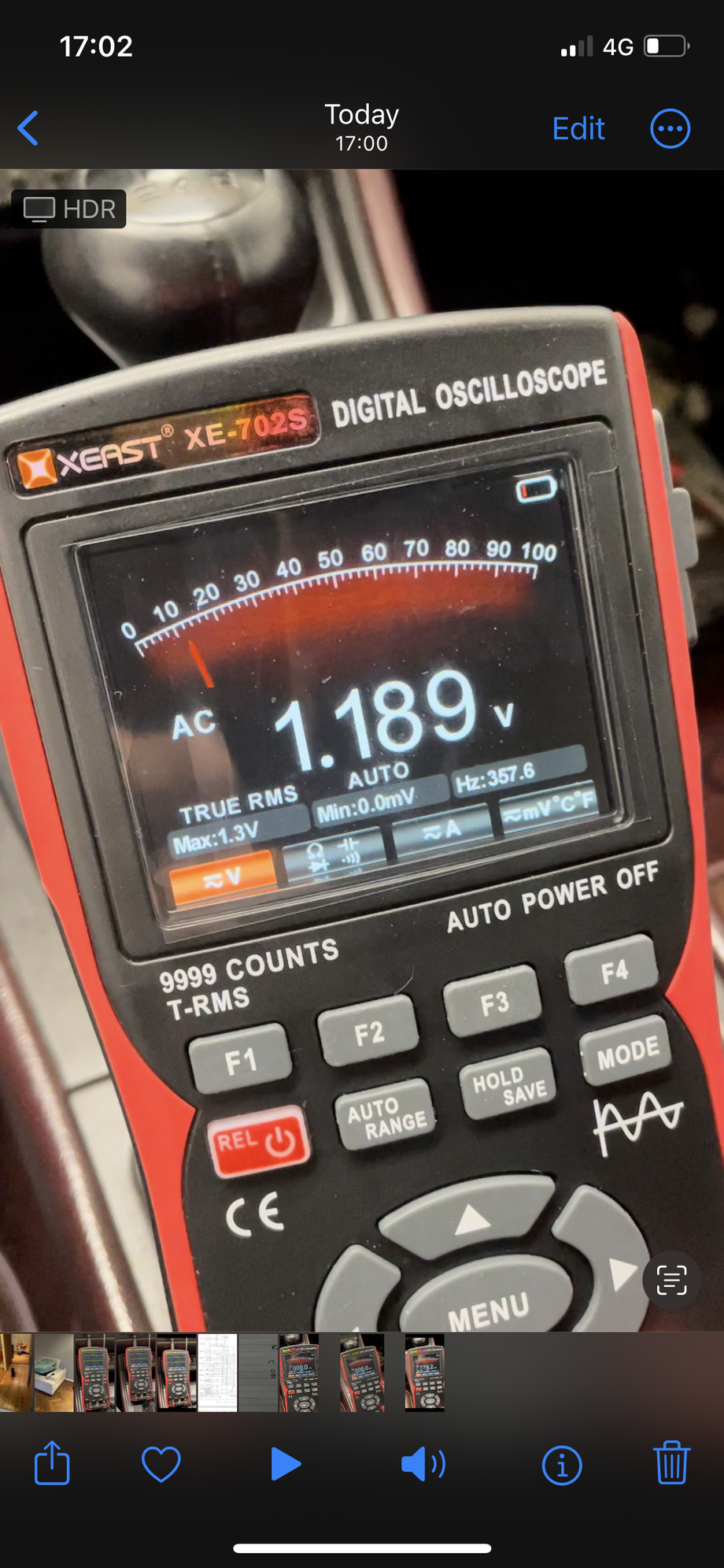
You're showing 1.189V and 0.779V. Presumably one is the reference sensor and the other the speed sensor? Which is which? Are they both gapped the same?
The lower picture also shows 49Hz instead of 357...
Your oscilloscope's low battery indicator appears to be on. I doubt that would affect the readings, but it might.
1.189V = Speed Sensor
0.779V = Reference Sensor
Why there is a difference in Hz I do not know. How could you gap the sensors differently? I always set the gap using the speed sensor and since both are attached to the same bracket I don't see how you could adjust the reference sensor differently? The speed sensor has the 8-shaped washer and the reference has none.
The flywheel has 58 teeth (but would have 60 without the gap). Your oscilloscope shows around 360 Hz on both the speed sensor waveform and RMS voltages, so it's seeing about 360 teeth a second. That equates to about 6 revolutions a second, or 360 a minute.
The reference sensor voltage screen shows 49Hz which is 2940 events per minute. At 360 RPM that's just over 8 events per revolution, which doesn't make any sense.
However, the waveform image of the reference sensor shows 3.89Hz. That would be one event per revolution at 233 RPM. Was it cranking slower then?
The battery was getting slightly low because of the cranking so 233 RPM might be realistic. I hooked up the car to charge overnight and I can try again tomorrow.
I have been following this thread with interest.
I struggle to read wiring schematics these days due to vision deterioration so please tell me if I make an error or omission .
It occurs to me that the speed and TDC reference sensors may be working ok but the problem is that the DME is not processing the information that it is receiving because it is not getting the 12v+ power that it needs or the DME grounds are not properly connected somewhere.
With the ignition on, do you see 12v+ at both terminals 18 and 35 of the DME plug ?
Check continuity between DME plug terminal 10 and ground points Vlll & lX which I believe are the DME grounding points.
Also check that an immobiliser (if fitted ) is not preventing the switched live from your Ignition switch reaching terminal 86 on the DME relay base. .
There is a loop on the bottom of plug E of the Fuse Relay board with a 1mm wire loop (Black/ Yellow wire). If there is an immobiliser fitted to your car that loop will have been cut and there will be 2x tails attached running to your immobiliser/ alarm This video might be helpful
All DME(ECU) ground pins (16,17,19,28) go to ground.
I have 12V at pin 18 and 35 with the ignition on.
I hooked up a loaned DME and KLR today with no success.
I am officially out of ideas and incredibly frustrated.
I don�t even know where I could go to to figure this out. I talked to a local Porsche specialist I had been at before but they seemed very reluctant to take on this job since I have been �messing around with it myself��
I assume you were putting the oscilloscope probe on the DME connector? Try unplugging the speed sensor and probing the connector directly and see what that gives you. (I think a Hall effect sensor actually generates a voltage from the magnetic field -- it doesn't modulate a voltage that it's getting from the DME.)
If its possible, take the readings at the sensors directly and compare with the readings at the DME. If they are in spec when measured at the sensor and out of spec at the DME, then it seems like its an issue with the wiring. If out of spec directly at the sensor then its an issue with the gap or the pickups on the flywheel, since the sensors are new. Im no expert but this is what I would do as a way to eliminate variables.
Now I am really confused. I was under the impression that when the DME(ECU) is not getting the right inputs it gives no signal to the injectors and the ignition coil right? I have been checking my plug and cylinders regularly and did not get any fuel in them but today while cranking I smelled some fuel and checked the cylinders again. I found them flooded with fuel... My heart really sank in that moment. I think fuel washing the cylinder wall was a big contributing factor to the engine damage in the first place so I am really paranoid about that happening again. I don't get why there is suddenly fuel in the cylinders? I blew out the fuel as best as I can and sprayed a little fogging oil into the cylinder.
I might need to take another break from this car. It's really wearing me down...
 04-14-2024, 12:43 PM