When you click on links to various merchants on this site and make a purchase, this can result in this site earning a commission. Affiliate programs and affiliations include, but are not limited to, the eBay Partner Network.
I assume you were putting the oscilloscope probe on the DME connector? Try unplugging the speed sensor and probing the connector directly and see what that gives you. (I think a Hall effect sensor actually generates a voltage from the magnetic field -- it doesn't modulate a voltage that it's getting from the DME.)
Originally Posted by walfreyydo
If its possible, take the readings at the sensors directly and compare with the readings at the DME. If they are in spec when measured at the sensor and out of spec at the DME, then it seems like it's an issue with the wiring. If out of spec directly at the sensor then it's an issue with the gap or the pickups on the flywheel, since the sensors are new. Im no expert but this is what I would do as a way to eliminate variables.
So I connect the oszilloscope at pin 25/26 and 8/27 at the sensor plug directly. Do I need to connect the 3rd pin to something?
All DME(ECU) ground pins (16,17,19,28) go to ground.
I have 12V at pin 18 and 35 with the ignition on.
I hooked up a loaned DME and KLR today with no success.
I am officially out of ideas and incredibly frustrated.
I don’t even know where I could go to to figure this out. I talked to a local Porsche specialist I had been at before but they seemed very reluctant to take on this job since I have been „messing around with it myself“…
I can understand the garage point of view. The problem for them is so much has been changed and plugged and unplugged that there could well be several issues now .
Don't give up just yet. The DME is clearly receiving the pulses from the speed and reference sensors so you probably need to move on to the next tests .
The problem is that you are testing things completely randomly and not following a sequential Bosch testing sequence . This can never work and will end up being very frustrating and expensive.
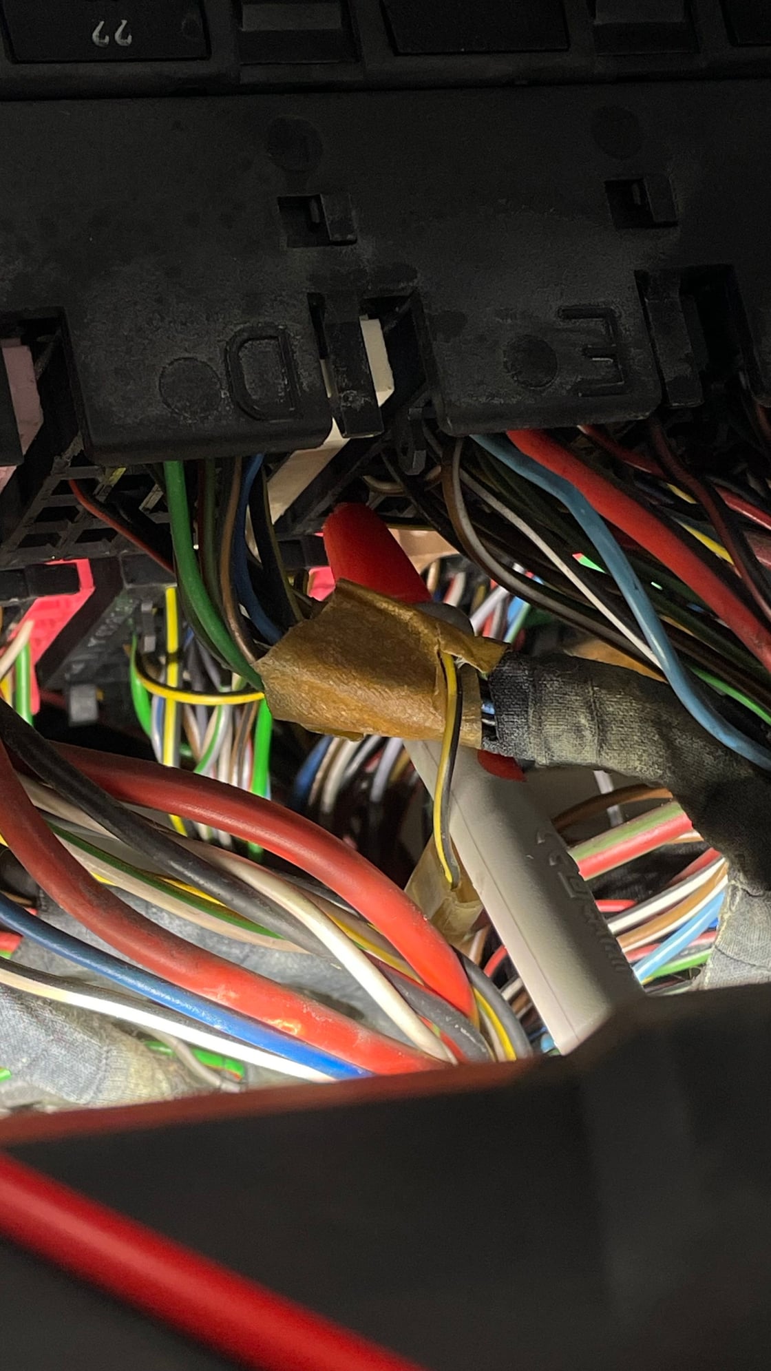
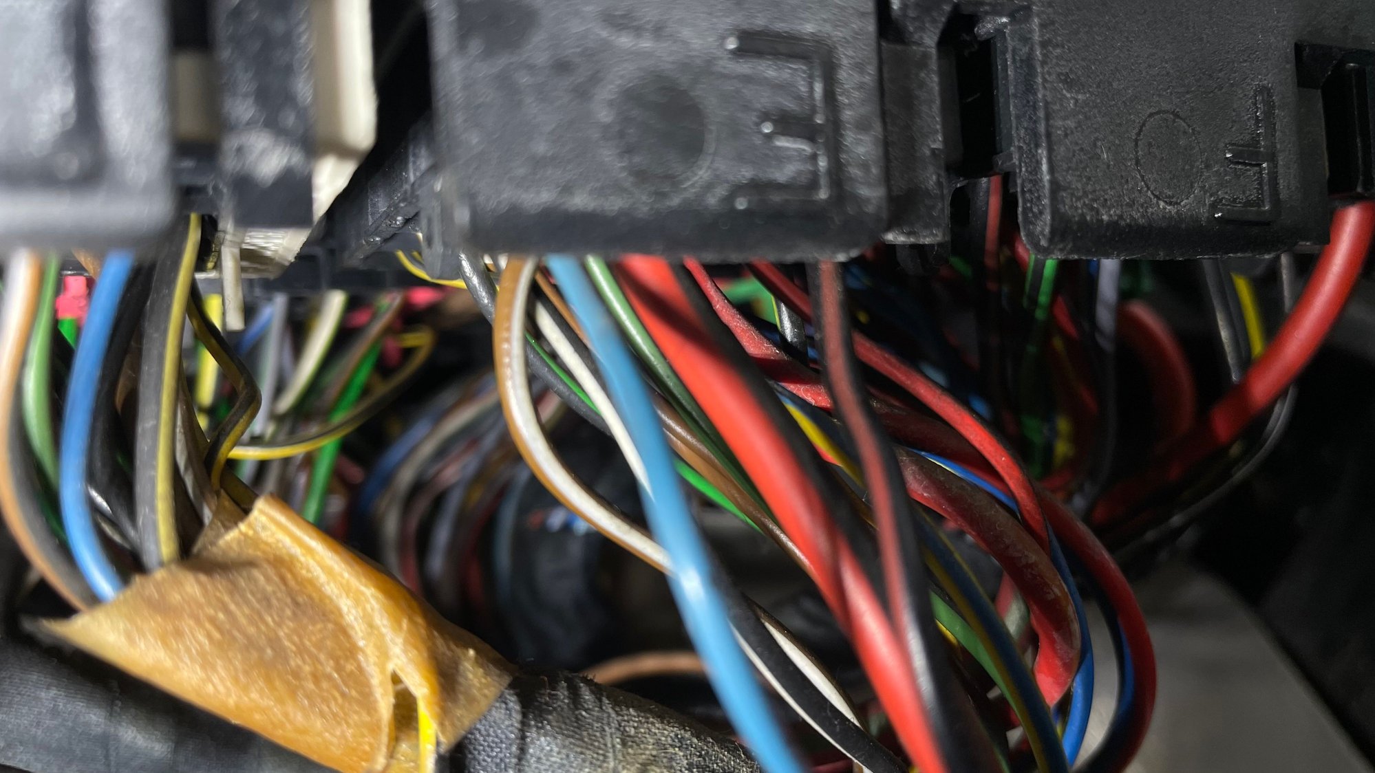
Did you pull the fuse relay board up and check the Black/Yellow loop on the E plug yet ???
This is important as there might be the residue of a former immobiliser circuit which is disabling an important continuity somewhere . its something we need to eliminate before we can move on.
Could you just remind me of the model year of your car and the engine size please to save me searching for it
I can understand the garage point of view. The problem for them is so much has been changed and plugged and unplugged that there could well be several issues now .
Don't give up just yet. The DME is clearly receiving the pulses from the speed and reference sensors so you probably need to move on to the next tests .
The problem is that you are testing things completely randomly and not following a sequential Bosch testing sequence . This can never work and will end up being very frustrating and expensive.
Did you pull the fuse relay board up and check the Black/Yellow loop on the E plug yet ???
This is important as there might be the residue of a former immobiliser circuit which is disabling an important continuity somewhere . its something we need to eliminate before we can move on
Sure, I can understand their point of view as well. Most likely I does not make much sense to give it away, but I am really running out of ideas.
Can I find the "sequential Bosch testing sequence" somewhere, sounds like a good way to go about it.
The car is a 1985 944 Turbo 2.5l.
Can you elaborate what you mean by Black/Yellow loop on the E plug? The car was never equipped with an immobiliser as far as I know, but I will check!
apologies ...I have been assuming that this was a 85.5 or later car...Ok so I believe that your fuse relay block doesn't look like the one in my video ?
Is it only accessible from inside the passenger foot well from underneath the dash or from under the hood.
I think it is pointless looking for an immobiliser ...much better to look at the E plug as suggested if you could please. I need to know if the loop is cut or intact
It�s probably one of the first turbos build and sold in 1985 but it�s of course the new design (85.5) like all turbos so my fuse box is like the one in the videos. Now I understand what you meant by E. I will check that and get back to you.
ahh thats good news. Working on your back in the passenger footwell in the dark is no fun look forward to hearing from you and moving to the next stage. of checks
So I connect the oszilloscope at pin 25/26 and 8/27 at the sensor plug directly. Do I need to connect the 3rd pin to something?
Are you sure that you have the correct sensors for your year car ? If you have a 3rd wire it must be the shield wire and usually goes to ground .
Could you list the part numbers of the ref and speed sensors you have fitted .
Are you sure that you have the correct sensors for your year car ? If you have a 3rd wire it must be the shield wire and usually goes to ground .
Could you list the part numbers of the ref and speed sensors you have fitted .
944 606 017 00, 944 606 015 00, 944 606 115 00 are the part numbers listed for my sensor. I don�t think there is any other sensor for the 944 and it fits all years if I am mistaken. They have 3 pins in the plug and since I was going to do the oscilloscope measurement with the sensor unplugged I was wondering what to with the 3rd pin. Shielding wire makes sense, thanks.
I do appreciate that even with all your meticulous testing that you still haven’t found the Non start issue or issues. We all know how utterly frustrating that can be.
So try and imagine how frustrating it can be for those of us who are in other States or even different Continents that are trying to help you but are unable to be there with you to make checks and test the Engine Management System components ourselves....... We are completely dependant on the information and answers that you provide in response to our questions .
I know that some of questions or test requests may not seem relevant or important to you but if you try to second guess and decide what is important and what is not then how are we going to be able to help you find a solution ?
Pulses from the reference and speed sensors to the DME are essential . Without them functioning correctly the DME cannot convert them into an AC input and therefore will not function.
You do not need to test them with an ocilloscope...... that is taking a sledge hammer to crack a nut. Just use a simple multi-meter and measure the ohms of each sensor at the DME plug terminals . You are looking for 600-1500 ohms
Speed sensor terminals 8 & 27ohms and TDC sensor terminals 25 & 26 ohms .If that checks out ok then there is nothing wrong with the functioning of those 2 sensors and the DME is receiving the correct signals so you need to move on.
Have you had a chance to check if the E connector on your Fuse Relay board has a black/yellow wire loop intact or not ?
I have asked you this vital question at least 3x times now without a response ? please don’t ask me to justify and explain the significance of every question that I ask . It is a simple matter of lifting the fuse box and looking at the connector, They are all clearly marked. If the loop is intact we can move on to the next troubleshooting sequence .
I do appreciate that even with all your meticulous testing that you still haven�t found the Non start issue or issues. We all know how utterly frustrating that can be.
So try and imagine how frustrating it can be for those of us who are in other States or even different Continents that are trying to help you but are unable to be there with you to make checks and test the Engine Management System components ourselves....... We are completely dependant on the information and answers that you provide in response to our questions .
I know that some of questions or test requests may not seem relevant or important to you but if you try to second guess and decide what is important and what is not then how are we going to be able to help you find a solution ?
Pulses from the reference and speed sensors to the DME are essential . Without them functioning correctly the DME cannot convert them into an AC input and therefore will not function.
You do not need to test them with an ocilloscope...... that is taking a sledge hammer to crack a nut. Just use a simple multi-meter and measure the ohms of each sensor at the DME plug terminals . You are looking for 600-1500 ohms
Speed sensor terminals 8 & 27ohms and TDC sensor terminals 25 & 26 ohms .If that checks out ok then there is nothing wrong with the functioning of those 2 sensors and the DME is receiving the correct signals so you need to move on.
Have you had a chance to check if the E connector on your Fuse Relay board has a black/yellow wire loop intact or not ?
I have asked you this vital question at least 3x times now without a response ? please don�t ask me to justify and explain the significance of every question that I ask . It is a simple matter of lifting the fuse box and looking at the connector, They are all clearly marked. If the loop is intact we can move on to the next troubleshooting sequence .
hi peanut! I did not want to undermine your testing efforts, since I really appreciate the help. I just wanted to explain my question about the 3rd terminal. Views on what need to be checked seem to be a bit diverse so i try to incorporate everyone�s advices.
The car is not at my place of living so sometimes it takes me a while to get back to it.
anyways, i will be at the car later today and I will give you an update about the E plug!
Edited.
ok I hadn't realised that your car was parked away from your home.
The 3rd wire. its a ground wire for the EMF shielding that is wrapped around you sensor wires which prevents external electrical interference. Check that 3rd wire does not connect to either of the other 2x wires then leave the wires unconnected for the time being if the sensors are working ok ....Later we will need to check which DME pin to connect the 3rd wires to .( I believe it is pin 19 )
When you have the E connector out ,check for the loop and then check that there is 12v+ on the Black /Yellow wire with the ignition switched on. This feed comes directly from terminal 15 on the Ignition switch so be careful...
For safety, pull the positive battery terminal off until you are ready to do the tests.
If you find that the loop has been cut and has 2x wires connected to the tails then you will need to cut off both the tails and tape them up .Then join the 2x short black/yellow yellow/black wires on the E connector together which should then give you a 12v+ at terminal 87 on the DME relay base which powers the Injectors and DME (DME terminals 18 & 35
Last edited by peanut; 04-21-2024 at 09:25 AM.
Reason: Correction regarding grounding of SRS & CPS 3rd shield wires
sorry but a lengthy post i just made has completely gone missing ?.... argghhhhh
i haven't the strength to re-type it all so a short note will have to do.
You really need to pull the E connector out of the block in order to see all the wires and make voltage and continuity test as in my video.
I didn't ask you if there is a immobiliser in place ...I only need to know if the fine black yellow or yellow black wires are formed into a small loop beneath the E connector block.
You have not mentioned terminal 87 ? this is probably the most critical terminal in the DME can. !
You need to check that there is 12v+ on Terminal 87 with the ignition on
Use your multimeter to check that terminal 85 is connected to ground .......It should be a constant ground ...ignition on or off..
If you have a ground on T 85 and 12v+ on T 86 then you should also see 12v+ on T 87 you need to check this.
The second DME relay solenoid comprises a switched 12v+ from terminal 30 within the DME relay can together with a ground that is made within the DME relay.
DO NOT connect terminal 85b to the chassis or bodywork . The ground for terminal 85b must only come from the DME never connect it to common ground . when the DME is happy that the sensors are providing the right information..it will ground terminal 85b and activate the second solenoid thus providing power to the fuel pump from terminal 87b.
Johnny
 04-18-2024, 03:17 PM

 The DME is clearly receiving the pulses from the speed and reference sensors so you probably need to move on to the next tests .
 look forward to hearing from you and moving to the next stage. of checks