When you click on links to various merchants on this site and make a purchase, this can result in this site earning a commission. Affiliate programs and affiliations include, but are not limited to, the eBay Partner Network.
Looking for ideas on this one. I've got a 951 Turbo racecar that was sent out for a cage. When I went to pick it up, it wouldn't start. I suspected the computer and was fortunate enough to have another 951 computer loaned to me. It's not the computer. Here's what I know...
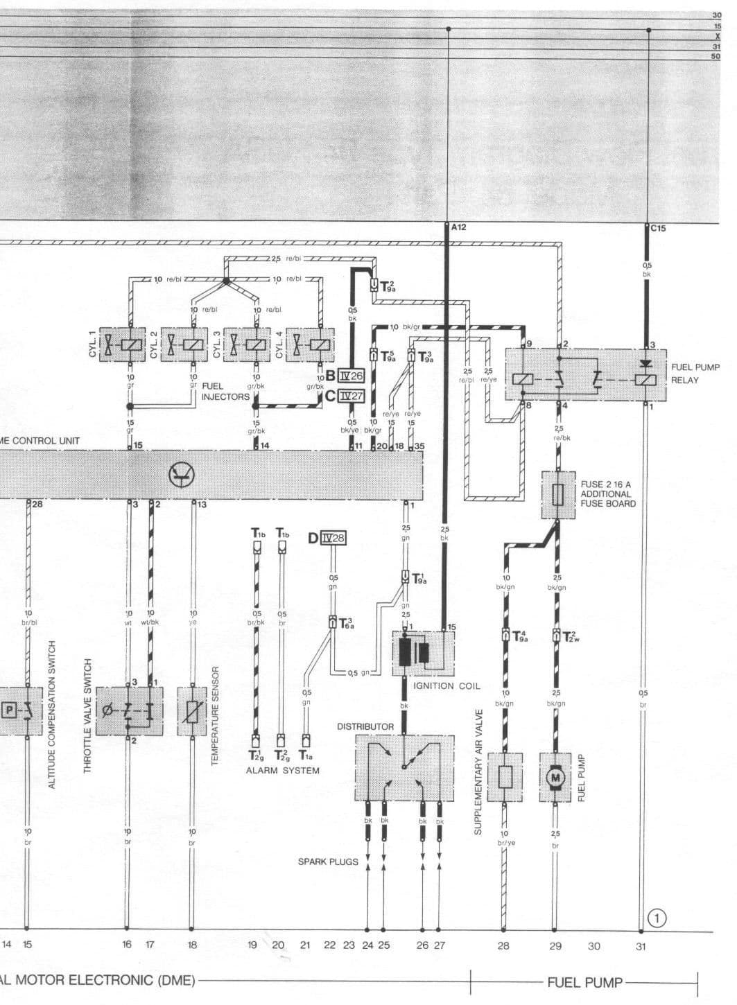
The DME relay is gone. We have the red/yellow wire and the fuel pump hard wired to power. They no longer require that relay. The #18 & #35 pins on the harness are getting power when the ignition and master switches are powered on. The black coil wire is getting power. The #14 & #15 EFI wires are not energized on the computer plug. I'm suspecting that because they aren't (and I'll check and verify) that the other EFI components aren't powering up either.
There should be 0 vdc at pins #14 and #15 on the DM We plug connector. The DME uses these connections to pulse the injectors to ground.
This electrical diagram should diagnose the problem
Last edited by T&T Racing; 01-20-2024 at 07:24 PM.
Right, and I've got a noid injector light on injector 1 with zero pulsing of the injectors. I have also removed the rail from the motor and placed Solo cups under the nozzles to catch fuel. I've got spark, I've also jumped the EFI harnes power (red wire/blue stripe) straight to the battery. Still nothing. No cycle of the injectors.
Originally Posted by T&T Racing
There should be 0 vdc at pins #14 and #15 on the DM We plug connector. The DME uses these connections to pulse the injectors to ground.
This electrical diagram should diagnose the problem
With the ignition switch in run position, test the voltage to ground for each FI connector. That is to measure the voltage to ground for the 2 pins of each connector. The voltage for each pin should be approximately 10.6 vdc
Can you show or describe where you made the direct connection from the positive terminal of the battery to the red/blue stripe wire supplying 12 vdc to FI connectors.
Last edited by T&T Racing; 01-22-2024 at 09:03 PM.
Sure. I ran a jumper wire from the PCM side of the 14 pin connector at the brake booster (cut the wire 3 inches before that plug) and from the wire to the battery terminal, then turned the PCM/positive side of the coil (Black wire), the PCM power wire (Red and yellow wire) all on with the control panel toggles that are wired to the master cut-off. I verified everything else was getting 12 volts dc. I've not been back to the shop yet this week to test each side of the injector terminals..
Originally Posted by T&T Racing
With the ignition switch in run position, test the voltage to ground for each FI connector. That is to measure the voltage to ground for the 2 pins of each connector. The voltage for each pin should be approximately 10.6 vdc
Can you show or describe where you made the direct connection from the positive terminal of the battery to the red/blue stripe wire supplying 12 vdc to FI connectors.
Showing 12.65 Vdc on both legs of the circuit. I think I need to trip that momentary circuit on either pin4 or pin7 to ground... I'll have to dig back through my old documentation from when I rewired my 944Spec car in 2019.
 01-20-2024, 03:41 PM