When you click on links to various merchants on this site and make a purchase, this can result in this site earning a commission. Affiliate programs and affiliations include, but are not limited to, the eBay Partner Network.
'Mates - as part of the spring overhaul the cracked injector boots are finally getting replaced. HA it' been on my list for literally years now.
But hey take a look - under the cracked 30 year old rubber is another layer of stuff? I changed the boot on one of the water temp sensors to the block and encountered similar but in the end judged it to be dried grease mushed in there as a water and dust repellant, I guess?
The injector connectors could be a similar story�the stuff is really tenacious�unlike the stuff under the temp sensor boot which was a bit compliant and believably dried grease, this stuff is hard as plastic, really, can hardly get a tool under it�and before I tear into it with too much enthusiasm thought I'd ask for some insights from those who have tackled this before.
A few more questions:
- I can easily find the EV-1 two-pin boots online, but can't find boots for the four-pin, and six-pin connectors I'd also like to replace. Sources?
- Any thoughts about the 90-degree boots available for the injector connectors? Seems like a good idea. For example.
- Finally I can't get a straight answer about whether to use grease on the inside of the boot to keep dirt and moisture out of the connector. Any thoughts?
Cheers
Sources: 944Online,
I install all my connectors dry.
I have thoughts about this. In no particular order to your questions:
- I like the 90 degree boots and they are my choice when replacing these things.
- It's not dried grease that you're seeing but rather a kind of potting material. I don't know the full history but I believe that these harnesses were made before the silicone seals that are now commonplace were available, and were the technology available at the time to seal things up.
- Mouser and Digikey are great sources for JPT connector housings and terminals, but I've never found the boots there.
- I've found the boots for larger connectors at milspecwiring.com (no affiliation)
- You are likely to find that the connector housings have the terminals pinned in place. You can see this by inspection of the housing itself; there are typically 2 rectangular indentations that were put in during manufacturing as a further deterrent to terminal removal. They're hidden right now under the boot but I'll bet a nickel you'll find them. It means that you won't be able to simply de-pin the connectors.
- Newer connector housings are made to accept silicone wire seals that fit snugly around the wires and into the housing. These seals get crimped on to the wider part of the new terminals, on the far end of the business end of the terminal. Between these and new boots, I think you'll have all the environmental protection you'll need for the next couple of decades. I don't add additional grease in the amounts you see of the potting material. However...
- I use silicone spray to help everything slide and click into place in the new housings.
- Make sure to get housings with the integrated spring retainer. I don't know if the really old school ones are available anymore anyway, but you should avoid the kind that makes you take off the metal retainer thing completely to unseat the connector.
I went with the Lindsey harnesses. The cost won't be too far off after the crimper tools, GXL wire, terminals, connectors, boots, sleaving, S&H, etc. Not to mention finding everything on the web and piecing it all together. Then building it so the end product looks professional...versus having 1 package show up at your door ready to install.
Tom, and Zirc—great information and suggestions. Tom y'know I thought about harness, and did look at Lindsey, but didn't see a 968 variant, only 951 & etc. Didn't pursue it too far beyond that peek and seeing the how-to's involving messing with the DME.
So per advice above got the connector kit from 944 online. Came today. Expensive, and more pieces than I really need, but easy one-stop shopping. Zirc I've disassembled one of the connectors already using standard pin-removal tool and didn't find the connectors fixed. But haven't undone the injector connectors yet so maybe there are adventures ahead of me.
Thanks again for your help.
On edit: milspec seems like a great resource. Thanks.
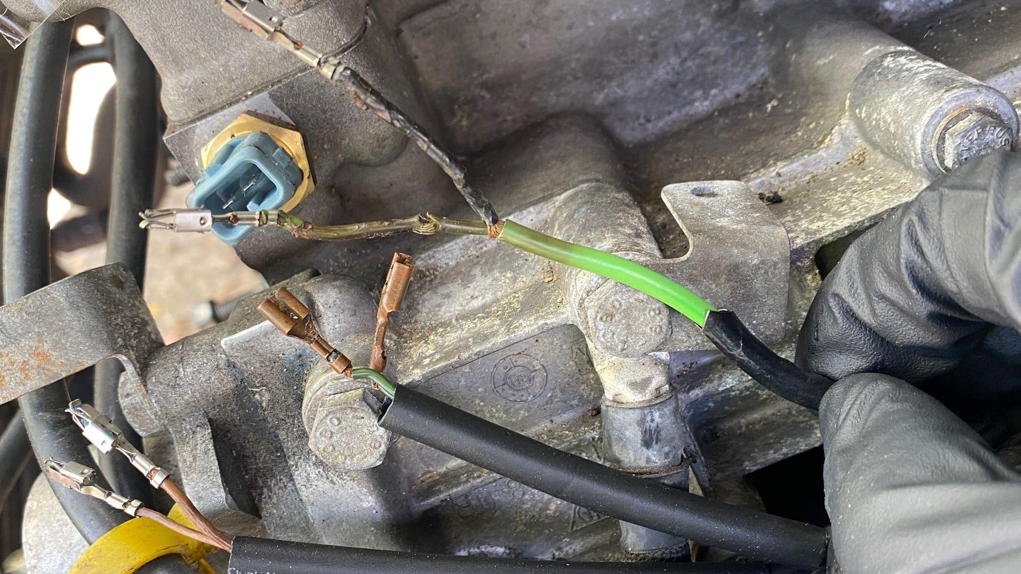
Veering ever-so slightly off-topic. But continuing to focus on connector questions. This one's about the knock sensors.
As you can see... after over 30 years of heat the plastic sheathings are hard as rock and don't bend at all. And not brittle, either! Necessitating a hard bend where this plastic ends near the connector. So we'll refresh these.
BUT
Can someone explain the wiring diagram hieroglyph?
What's the 0.75 WT dashed surround with the terminal 1 wire within? What are the little ellipses, with small pointers, at either end, sometimes numbered, sometimes not?
What does terminal 2 connect with? Clearly in the photo there are two wires coming from the harness. Maybe some kind of stranded sheath? Before tearing it apart thought I'd better check with the group.
With that ellipse, what you're seeing is the shield on that wire and how it interacts with the normal ground wire. In this case, what you're seeing is that pin 2 and the shield are spliced on the terminal and at the ground point (102, on the diagram). For whatever reason it looks like there should be a right angle join on the diagram, but I think it corresponds to what you're seeing on the physical connector. If you cut back on the main green wire/cable, you'll find the braided shield that needs to get spliced to the ground wire.
I hope that helps clear things up, it sounds like you knew what was going on.
Generally speaking the shield on a coax cable should be grounded at one end only. (Which end probably doesn't matter here, but grounding both ends can create a ground loop.)
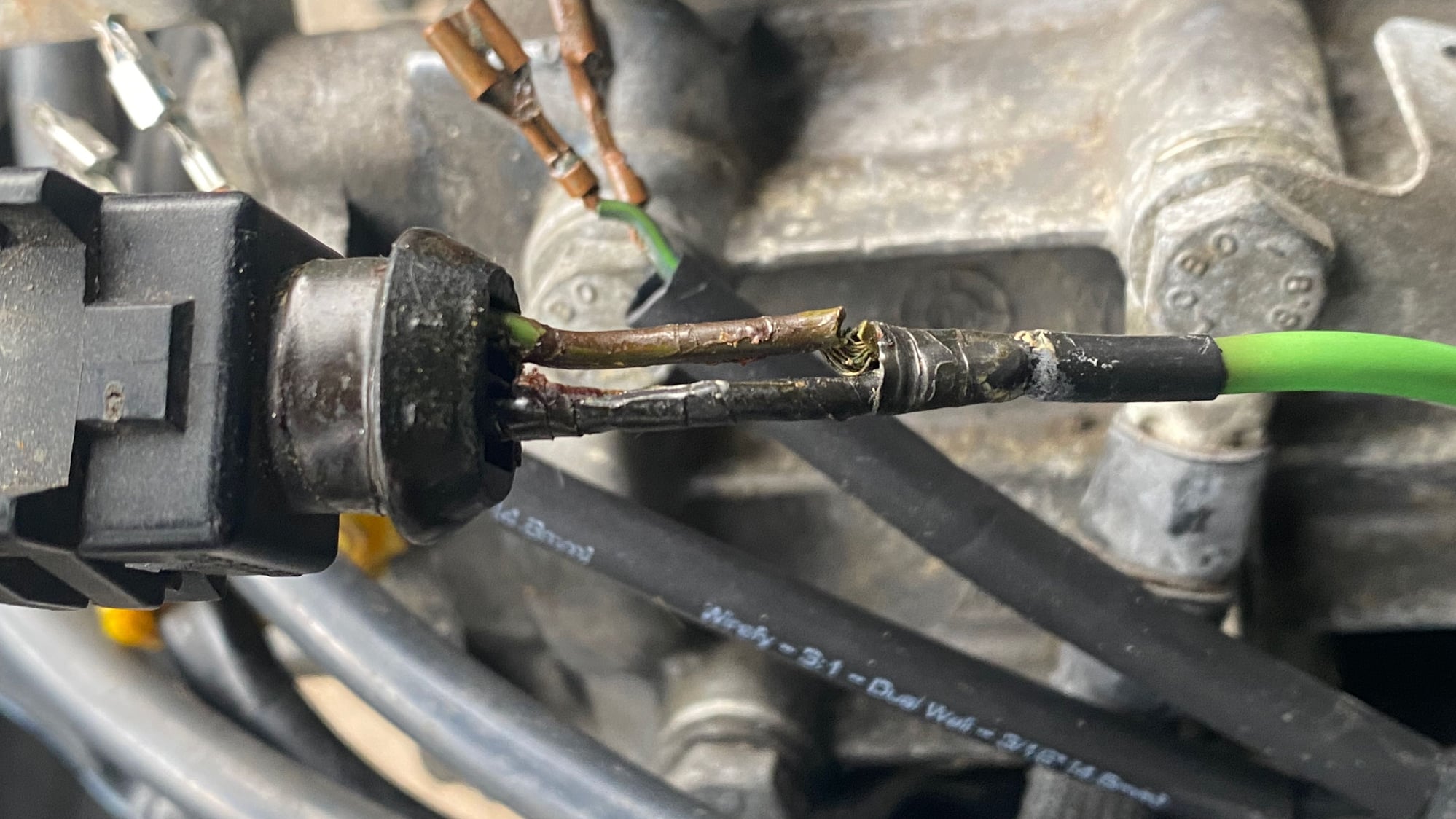
So it's Saturday, it's nice out, back to working on the car. Anyone have any advice about what to do about wire insulation that has become super-stiff and brittle over the years? In the photo, you can see where the now-rigid insulation has broken on the dark green wire, rather than bent, creating a vibration stress point for eventual wire failure. The stiff dark-green insulation extends into the still-flexible lighter-green sheathing another inch or so. The dark-green stuff doesn't bend... at all.
I've got some of those heat-shrink-with-solder butt joint splices to use here.
I could cut the hard stuff back into the flexible zone but I'm getting nervous about cutting too far back into the harness. Grateful for any thoughts or reassurance.
Apologies for my questions piling up—keeping this "injector harness repair" thread together—might make it easier for someone in the future.
@951Tom I know you're smiling right now and thinking "I told him to buy the harness kit..." 😏
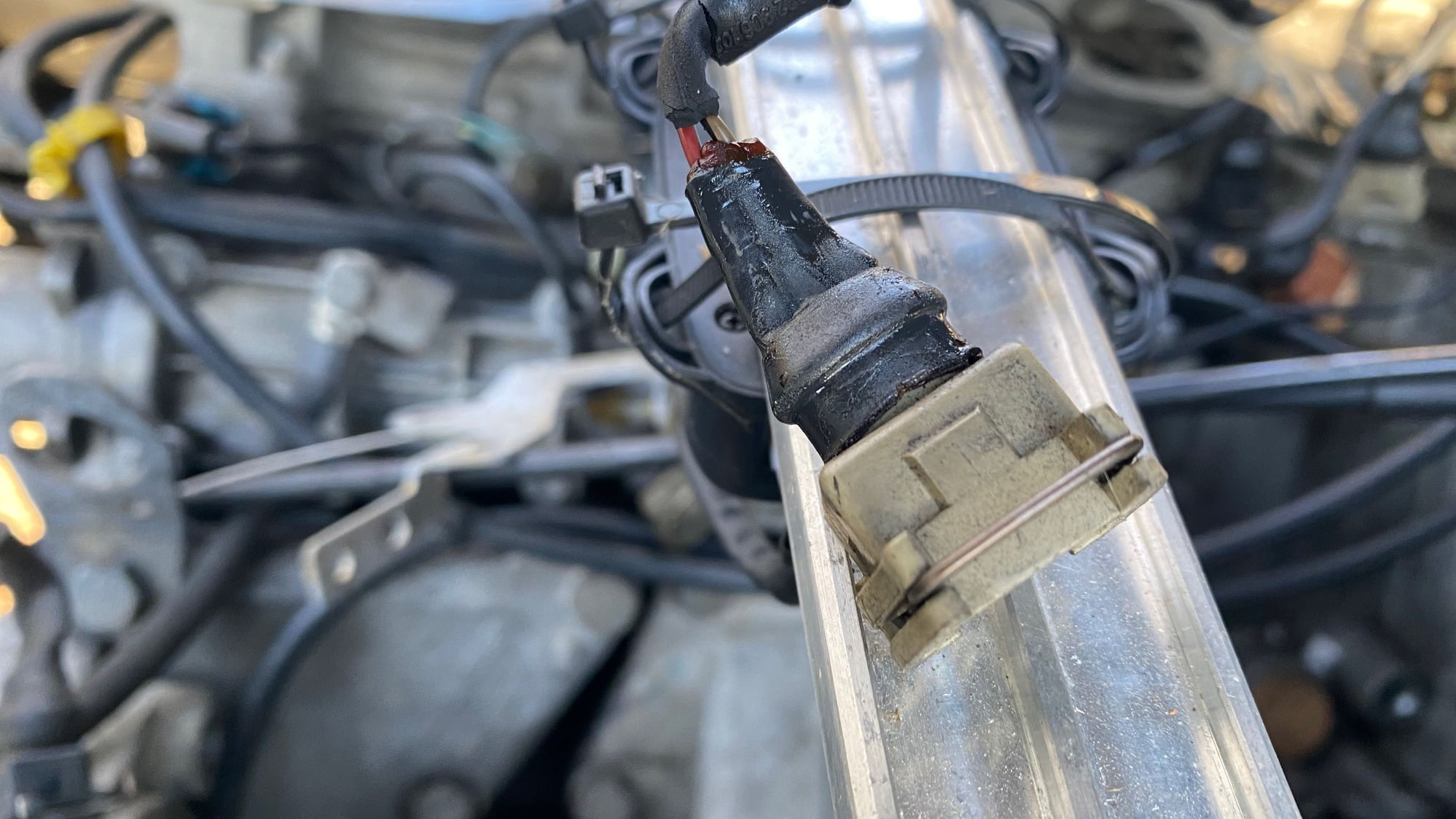
I posted a pic of my Hall Sender connector on the 968 forum but continuing here with a question about the coaxial braid around the hall sender wires. I have a nice new 3-connector replacement with new boot and 6-inch pigtails.
Does the braided wire serve a shielding function that needs to be maintained? As you know, this lead wraps pretty tightly around the distributor housing so I'm wondering if the braid is there for a reason?
I compromised the braid a bit getting the #$%%*^ hard casing off, easy enough to cut back and splice and shrink-wrap but don't know if that braid should extend right up to the connector, as it came from the factory?
Apologies for my questions piling up�keeping this "injector harness repair" thread together�might make it easier for someone in the future.
@951Tom I know you're smiling right now and thinking "I told him to buy the harness kit..." 😏
I posted a pic of my Hall Sender connector on the 968 forum but continuing here with a question about the coaxial braid around the hall sender wires. I have a nice new 3-connector replacement with new boot and 6-inch pigtails.
Does the braided wire serve a shielding function that needs to be maintained? As you know, this lead wraps pretty tightly around the distributor housing so I'm wondering if the braid is there for a reason?
I compromised the braid a bit getting the #$%%*^ hard casing off, easy enough to cut back and splice and shrink-wrap but don't know if that braid should extend right up to the connector, as it came from the factory?
As always, big thanks. THEORY
PRACTICE
the braid is there to shield the circuit from electrical interference such as from the starter or ignition coil. It needs to be connectEd to pin 3
 03-16-2024, 08:04 PM


 Anyone have any advice about what to do about wire insulation that has become super-stiff and brittle over the years? In the photo, you can see where the now-rigid insulation has broken on the dark green wire, rather than bent, creating a vibration stress point for eventual wire failure. The stiff dark-green insulation extends into the still-flexible lighter-green sheathing another inch or so. The dark-green stuff doesn't bend... at all.