DIY - $30 Power Lock Conversion
 08-18-2013, 11:08 PM
#1
Advanced
Thread Starter
Hey guys and gals,
Just installed the power locks in my 85/2 944 n/a and couldn't be happier! It was such a pain to always have to reach over to open the passenger door, so this solved the problem - and for ~$30 bucks you cant beat it! I hope this guide is able to help someone in the future.
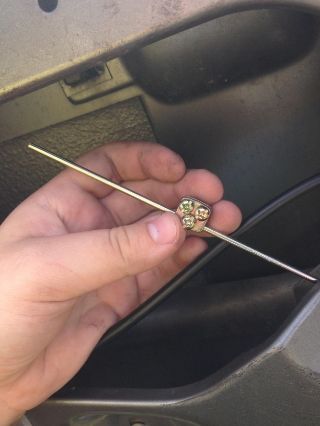
The remote and actuator from my kit:

NOTE: If you are not comfortable 1) removing your carpet or 2) drilling holes in your door, this DIY may not be for you
Tools needed:
- Drill & proper-sized drill bits for metal
- Somewhat heavy duty wire cutter
- Wire stripper OR scissors
- Wire crimper OR soldering iron & solder (you can either crimp the wires together or solder them)
- Phillips screwdriver
- 10mm socket and wrench (optional)
- Voltage meter
- OPTIONAL: 24MM Deep socket and wrench to remove the steering wheel. When wiring, it can be a giant pain in the butt.
Materials Needed:
- Power Lock Conversion Kit (includes wireless remotes and receivers as well as at least 2 actuators, rods and connecting pieces)
- Electrical connectors (not req'd if using solder; $5 kit at harbor freight)
- Electrical tape
- 3M Spray Adhesive (for carpet)
- Some washers that will fit the connecting screws
- 10A inline fuse (unless the receiver module has one on the power line already)
- ZIP TIES!!!
First few things before we start:
1. Make sure your actuators work! Plug them into the harness that comes with the receiver module (black box with antenna) and hook that up to 12VDC and ground (you can use your car battery, but be careful). Once you click unlock/lock on your remote, the actuator should propel forward and backward, respectively. There should be no other movement....its 0% or 100%. If it does have other movement without a load, contact the supplier for a replacement!
2. DISCONNECT THE BATTERY
OK, moving on.
Here is an outline of the steps:
1. Disconnect the battery.
2. Remove the driver side door panel and set aside
3. Mount the actuator and test
4. Run the wires through the door
5. Repeat steps 2-4 for the passenger side
6. Connect constant 12VDC and ground to the receiver module
7. Tuck the wires
8. TEST, TEST, TEST.
9. Put back the door panels
Note: The driver's side door is made to note let you lock it unless the door is 'closed'. This is so you don't lock it and forget your key inside your car. Make sure that when you are testing, the door is in the 'closed' state. You can simply do this by closing the latch like so:

STEP 1: DISCONNECT THE BATTERY
STEP 2: REMOVING THE DOOR PANELS
Remove all of the phillips screws indicated by the red arrows:

Pry out the corners of the door panel to release the clips. Pull out and disconnect the window switches. Pull up on the door panel to clear the locking indicator, and set the door panel aside.
STEP 3: MOUNT THE ACTUATOR AND TEST
When I first started this project, I saw a hole in the driver's side door that was TERRIBLY convenient to use as a mounting screw location. Turns out, it was a hole that is used for the locking pins from the door panel. So, the pictures show me using that specific hole, but in reality, a new hole is needed. Note that the actuators that came in my kit (and most of them on the market) will actually have two locations for mounting screws. I used one. Partly because I'm lazy, and partly because I didn't want to drill another hole in the door.
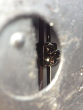
The actuator mounting holes:

First, you want to test the position of the actuator and make sure its good.
1. Put the connecting rod through the end of the actuator
2. Screw partly in the three small phillips into the connecting piece. Thread the connecting piece on the connecting rod like so:
--->connecting piece w/ screws

--->connecting piece on connecting rod
3. Place the actuator in the ball park position, on the wall of the door closest to you.
4. Play with the connecting piece and connecting rod with the door in LOCKED mode and the solenoid in CLOSED mode. You will want to put the connecting piece on the existing rod in this particular spot, so that you can screw it on through the hole like so:
--->View of the connecting piece on the existing rod and new rod
--->Securing the connecting piece to the existing rod:
5. At this point, you need to test that the actuator is in the right position. Connect the receiver module to 12VDC and ground, connect the actuator to the appropriate cables on the harness (they are color coded), hold the actuator in the position you want, and test. Make sure that the door is actually unlocking and locking properly.
6. If the door locks and unlocks properly, disconnect the 12VDC and ground and continue. If the actuator does a bouncy sort of action, the connecting piece is not in a good spot. Disconnect the connecting piece, make sure the door is in the lock state and the solenoid is closed, and mount again. You may have to play with it to get it in the right spot.
7. Loosen the screw that fixes the new connecting rod to the connecting piece, since you will be moving the actuator.
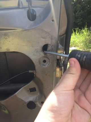
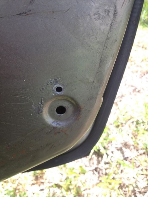
9. Locate the existing hole in the lowest corner of the door seen in this picture:
NOTE: As I mentioned earlier, these pictures arent accurate. You will be drilling a hole about a centimeter above the hole in this picture.
10. Find the proper sized metal drill bit (for the mounting screws) and drill a hole about a centimeter or so directly above the existing hole. At this point, you can measure the distance from the mounting holes on the actuator, translate that to the door and drill another matching hole for the second mounting screw. I skipped this step because it seems secure enough to me!
--->Newly drilled hole
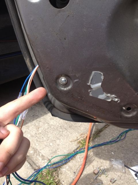
11. Hold the actuator from one side as you match up the lower mounting hole and screw in the mounting screw and washer to secure the actuator.
12. Ensure the door is in the LOCKED position and the solenoid is in the CLOSED position.
13. Re-tighten the connecting piece to the connecting rod in its fully extended state.
14. Re-connect the receiver to 12VDC/Ground and test to make sure the actuator is locking/unlocking the door. At this point, visually inspect the actuator to make sure it is secure while it is unlocking and locking.
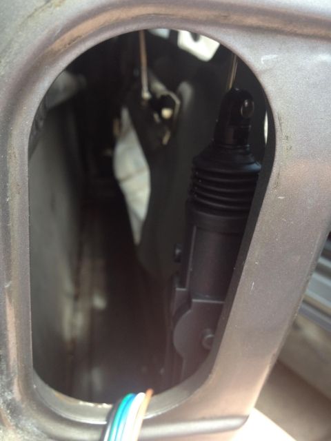
---->Picture of the actuator mounted:
STEP 4: RUN THE WIRES THROUGH THE DOOR
A note of caution, this is the most annoying part. You MUST peel back the carpet, and if you are like me - this hurts you inside. Have no fear, 3M spray adhesive will put it back just the way it was!
Another note: it helps to sort out the wires prior to routing them through the door. I laid mine out on the living room floor, de-tangled them and zip-tied the lines I wouldnt need. In my kit, the lines for each solenoid were green and blue. Considering we will only be using 2 out of 4 actuators that come in the kit, you will not need 4 of the connections. I used the master connection (which you must - 5 wires) and then the last slave connection (blue and green). This allows me to zip-tie the unused middle connections and tuck them away. If you are reading this DIY prior to having the kit in front of you, you will understand once you see the harness.
On to the wire routing:
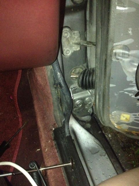
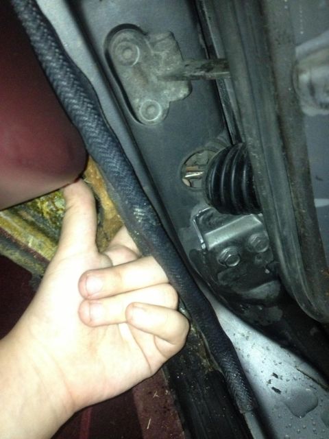
1. Pull back the rubber boot near the door hinge to reveal the wires.
2. Tug on the black trim that holds the carpet near the trunk switch:
--->The black strip pulled out on the passenger side and a view of the rubber boot pulled back exposing the wires:
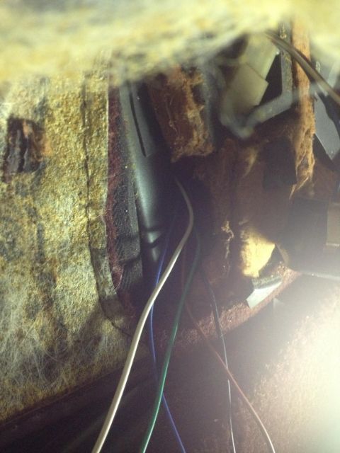
3. Peel back the carpet to expose some of the insulation.
4. You will have to stick your finger behind the insulation and see if you can find the hole where the wires go through to the door. This took the most time for me - partly because I really didn't want to remove the carpet. But once you remove the carpet, it takes two seconds to find the hole.
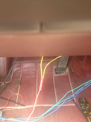
--->Driver's side view of wires from the receiver module going in through the area behind the carpet into the hole for the door wires
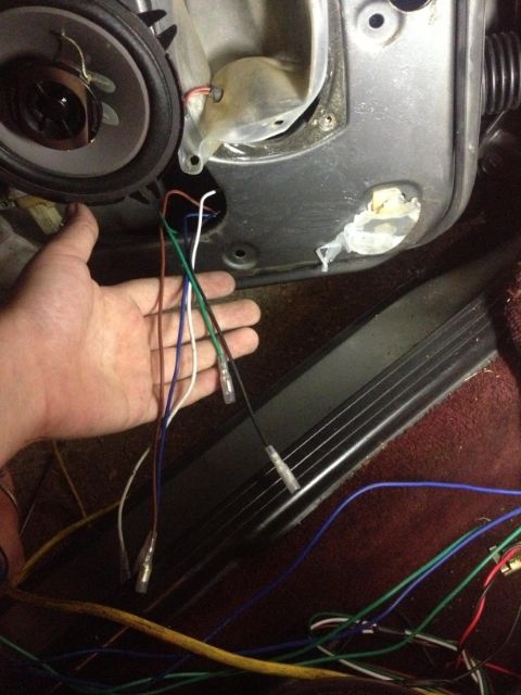
5. At this point, you have to feed the wires from the harness for the 'master' actuator, I believe it is blue, green, white, brown and black wires. Push them through the insulation, into the hole by the rubber boot and then through the door. You can use zip ties, a claw, a coat hanger, etc. to route the wires through.
Here are a few pictures from both the driver's and passenger's side wire routing:
--->Driver's side: Showing the cables from the 'master' actuator that need to be connected to the wires routed through the door:
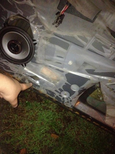
--->Passenger side door, showing where to peel back the plastic to stick your hands through and find the wires
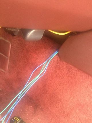
--->Passenger side: Showing the route that the wire needs to go with my finger
STEP 5: REPEAT STEPS 2-4 FOR THE PASSENGER SIDE
Reference the pictures above for the passenger side wiring and installation. Note that you can route the wires behind your radio as shown in the following picture:
--->Wires for passenger side actuator route:
STEP 6: CONNECT THE RECEIVER MODULE TO CONSTANT 12VDC AND GROUND
The method in which you get constant 12VDC is entirely up to you. This is where the voltmeter, connectors and wire crimpers (or solder and soldering iron) will become handy. You could go use any of the following as CONSTANT 12VDC sources:
- Tap into your radio harness (what I did)
- Go directly from your battery (arguably the smartest route)
- Tap into one of the factory switches (not a smart route)
You get the picture!
NOTE: You will need an INLINE FUSE ~10A on the constant 12VDC line. I presume that most of the receiver modules will have this already, but if not - you need to add one (you can get one at radioshack). Remember, the chassis is the ground, so you can look around for good spots behind the steering wheel to find ground locations.
--->Constant 12VDC line from radio (Note: mine is yellow but yours might be different)
STEP 7: TUCK THE WIRES
The way that you tuck the wires is also up to you. I zip-tied them together and used electrical tape to tape them to the door in multiple locations. As far as the wireless receiver, I haven't mounted it yet but my plan is to mount it behind the steering wheel (under the instrument cluster). You could also mount the receiver module behind your radio, which was another consideration of mine.
STEP 8: TEST, TEST, TEST
At this point, you're almost done. With the remotes, test to make sure both doors lock and unlock. Close the doors and make sure you can open them when unlocked, and can't when locked. If the actuator is doing some type of back and forth movement, the connecting rod is not on correctly. Keep adjusting until it is moving how you want it.
STEP 9: Put everything back together
At this point, you're done!
Put the plastic, door panels and carpet back. Use the 3M spray adhesive, which works very well, to glue the carpets back on.
Hope this works out well for everyone as it did for me!
- Lina
Just installed the power locks in my 85/2 944 n/a and couldn't be happier! It was such a pain to always have to reach over to open the passenger door, so this solved the problem - and for ~$30 bucks you cant beat it! I hope this guide is able to help someone in the future.
The remote and actuator from my kit:
NOTE: If you are not comfortable 1) removing your carpet or 2) drilling holes in your door, this DIY may not be for you
Tools needed:
- Drill & proper-sized drill bits for metal
- Somewhat heavy duty wire cutter
- Wire stripper OR scissors
- Wire crimper OR soldering iron & solder (you can either crimp the wires together or solder them)
- Phillips screwdriver
- 10mm socket and wrench (optional)
- Voltage meter
- OPTIONAL: 24MM Deep socket and wrench to remove the steering wheel. When wiring, it can be a giant pain in the butt.
Materials Needed:
- Power Lock Conversion Kit (includes wireless remotes and receivers as well as at least 2 actuators, rods and connecting pieces)
- Electrical connectors (not req'd if using solder; $5 kit at harbor freight)
- Electrical tape
- 3M Spray Adhesive (for carpet)
- Some washers that will fit the connecting screws
- 10A inline fuse (unless the receiver module has one on the power line already)
- ZIP TIES!!!
First few things before we start:
1. Make sure your actuators work! Plug them into the harness that comes with the receiver module (black box with antenna) and hook that up to 12VDC and ground (you can use your car battery, but be careful). Once you click unlock/lock on your remote, the actuator should propel forward and backward, respectively. There should be no other movement....its 0% or 100%. If it does have other movement without a load, contact the supplier for a replacement!
2. DISCONNECT THE BATTERY
OK, moving on.
Here is an outline of the steps:
1. Disconnect the battery.
2. Remove the driver side door panel and set aside
3. Mount the actuator and test
4. Run the wires through the door
5. Repeat steps 2-4 for the passenger side
6. Connect constant 12VDC and ground to the receiver module
7. Tuck the wires
8. TEST, TEST, TEST.
9. Put back the door panels
Note: The driver's side door is made to note let you lock it unless the door is 'closed'. This is so you don't lock it and forget your key inside your car. Make sure that when you are testing, the door is in the 'closed' state. You can simply do this by closing the latch like so:
STEP 1: DISCONNECT THE BATTERY
STEP 2: REMOVING THE DOOR PANELS
Remove all of the phillips screws indicated by the red arrows:
Pry out the corners of the door panel to release the clips. Pull out and disconnect the window switches. Pull up on the door panel to clear the locking indicator, and set the door panel aside.
STEP 3: MOUNT THE ACTUATOR AND TEST
When I first started this project, I saw a hole in the driver's side door that was TERRIBLY convenient to use as a mounting screw location. Turns out, it was a hole that is used for the locking pins from the door panel. So, the pictures show me using that specific hole, but in reality, a new hole is needed. Note that the actuators that came in my kit (and most of them on the market) will actually have two locations for mounting screws. I used one. Partly because I'm lazy, and partly because I didn't want to drill another hole in the door.
The actuator mounting holes:
First, you want to test the position of the actuator and make sure its good.
1. Put the connecting rod through the end of the actuator
2. Screw partly in the three small phillips into the connecting piece. Thread the connecting piece on the connecting rod like so:
--->connecting piece w/ screws
--->connecting piece on connecting rod
3. Place the actuator in the ball park position, on the wall of the door closest to you.
4. Play with the connecting piece and connecting rod with the door in LOCKED mode and the solenoid in CLOSED mode. You will want to put the connecting piece on the existing rod in this particular spot, so that you can screw it on through the hole like so:
--->View of the connecting piece on the existing rod and new rod
--->Securing the connecting piece to the existing rod:
5. At this point, you need to test that the actuator is in the right position. Connect the receiver module to 12VDC and ground, connect the actuator to the appropriate cables on the harness (they are color coded), hold the actuator in the position you want, and test. Make sure that the door is actually unlocking and locking properly.
6. If the door locks and unlocks properly, disconnect the 12VDC and ground and continue. If the actuator does a bouncy sort of action, the connecting piece is not in a good spot. Disconnect the connecting piece, make sure the door is in the lock state and the solenoid is closed, and mount again. You may have to play with it to get it in the right spot.
7. Loosen the screw that fixes the new connecting rod to the connecting piece, since you will be moving the actuator.
9. Locate the existing hole in the lowest corner of the door seen in this picture:
NOTE: As I mentioned earlier, these pictures arent accurate. You will be drilling a hole about a centimeter above the hole in this picture.
10. Find the proper sized metal drill bit (for the mounting screws) and drill a hole about a centimeter or so directly above the existing hole. At this point, you can measure the distance from the mounting holes on the actuator, translate that to the door and drill another matching hole for the second mounting screw. I skipped this step because it seems secure enough to me!
--->Newly drilled hole
11. Hold the actuator from one side as you match up the lower mounting hole and screw in the mounting screw and washer to secure the actuator.
12. Ensure the door is in the LOCKED position and the solenoid is in the CLOSED position.
13. Re-tighten the connecting piece to the connecting rod in its fully extended state.
14. Re-connect the receiver to 12VDC/Ground and test to make sure the actuator is locking/unlocking the door. At this point, visually inspect the actuator to make sure it is secure while it is unlocking and locking.
---->Picture of the actuator mounted:
STEP 4: RUN THE WIRES THROUGH THE DOOR
A note of caution, this is the most annoying part. You MUST peel back the carpet, and if you are like me - this hurts you inside. Have no fear, 3M spray adhesive will put it back just the way it was!
Another note: it helps to sort out the wires prior to routing them through the door. I laid mine out on the living room floor, de-tangled them and zip-tied the lines I wouldnt need. In my kit, the lines for each solenoid were green and blue. Considering we will only be using 2 out of 4 actuators that come in the kit, you will not need 4 of the connections. I used the master connection (which you must - 5 wires) and then the last slave connection (blue and green). This allows me to zip-tie the unused middle connections and tuck them away. If you are reading this DIY prior to having the kit in front of you, you will understand once you see the harness.
On to the wire routing:
1. Pull back the rubber boot near the door hinge to reveal the wires.
2. Tug on the black trim that holds the carpet near the trunk switch:
--->The black strip pulled out on the passenger side and a view of the rubber boot pulled back exposing the wires:
3. Peel back the carpet to expose some of the insulation.
4. You will have to stick your finger behind the insulation and see if you can find the hole where the wires go through to the door. This took the most time for me - partly because I really didn't want to remove the carpet. But once you remove the carpet, it takes two seconds to find the hole.
--->Driver's side view of wires from the receiver module going in through the area behind the carpet into the hole for the door wires
5. At this point, you have to feed the wires from the harness for the 'master' actuator, I believe it is blue, green, white, brown and black wires. Push them through the insulation, into the hole by the rubber boot and then through the door. You can use zip ties, a claw, a coat hanger, etc. to route the wires through.
Here are a few pictures from both the driver's and passenger's side wire routing:
--->Driver's side: Showing the cables from the 'master' actuator that need to be connected to the wires routed through the door:
--->Passenger side door, showing where to peel back the plastic to stick your hands through and find the wires
--->Passenger side: Showing the route that the wire needs to go with my finger
STEP 5: REPEAT STEPS 2-4 FOR THE PASSENGER SIDE
Reference the pictures above for the passenger side wiring and installation. Note that you can route the wires behind your radio as shown in the following picture:
--->Wires for passenger side actuator route:
STEP 6: CONNECT THE RECEIVER MODULE TO CONSTANT 12VDC AND GROUND
The method in which you get constant 12VDC is entirely up to you. This is where the voltmeter, connectors and wire crimpers (or solder and soldering iron) will become handy. You could go use any of the following as CONSTANT 12VDC sources:
- Tap into your radio harness (what I did)
- Go directly from your battery (arguably the smartest route)
- Tap into one of the factory switches (not a smart route)
You get the picture!
NOTE: You will need an INLINE FUSE ~10A on the constant 12VDC line. I presume that most of the receiver modules will have this already, but if not - you need to add one (you can get one at radioshack). Remember, the chassis is the ground, so you can look around for good spots behind the steering wheel to find ground locations.
--->Constant 12VDC line from radio (Note: mine is yellow but yours might be different)
STEP 7: TUCK THE WIRES
The way that you tuck the wires is also up to you. I zip-tied them together and used electrical tape to tape them to the door in multiple locations. As far as the wireless receiver, I haven't mounted it yet but my plan is to mount it behind the steering wheel (under the instrument cluster). You could also mount the receiver module behind your radio, which was another consideration of mine.
STEP 8: TEST, TEST, TEST
At this point, you're almost done. With the remotes, test to make sure both doors lock and unlock. Close the doors and make sure you can open them when unlocked, and can't when locked. If the actuator is doing some type of back and forth movement, the connecting rod is not on correctly. Keep adjusting until it is moving how you want it.
STEP 9: Put everything back together
At this point, you're done!
Put the plastic, door panels and carpet back. Use the 3M spray adhesive, which works very well, to glue the carpets back on.
Hope this works out well for everyone as it did for me!
- Lina

The following users liked this post:
afeudale (07-11-2021)
08-19-2013, 12:48 AM
#2
Burning Brakes
Join Date: Mar 2004
Location: Calif
Posts: 1,151
Likes: 0
Received 0 Likes
on
0 Posts
I did this exact thing about 25 years ago, shortly after getting the car - I used an after market alarm that had relay control - eventually the alarm started to drain the battery and I removed it - I have added keyless entry to several 944s since, the others have had the electric door locks and so the only thing needed was to connect the receiver to the door lock control - on my car at least, I needed to add a pair of relays to manage the switching, and I added a factory door lock switch in the center console
08-19-2013, 12:48 AM
#3
Advanced
Thread Starter
Awesome review, Lina! Thanks for posting it up.
Question. I already have the factory locking, but the control module that attaches to the steering column under the dash is acting up and lacks a remote. Do you think I could just order one of these kits and grab the wiring off of the stock control module and replace it with the kit one?
Question. I already have the factory locking, but the control module that attaches to the steering column under the dash is acting up and lacks a remote. Do you think I could just order one of these kits and grab the wiring off of the stock control module and replace it with the kit one?
Nice signature!
I'm not familiar with the locking system that comes in the car so I can't say for sure. But what I would do if I were you would be to try and trace the wiring and see if it is similar to the kit. You will be replacing the module for the receiver module and remote that comes in the kit. The problem with this is that the receiver module that comes in the kit might lack all of the outputs you need to control. I would start with figuring out what your factory module controls and the wiring that comes with it to see if you can buy a universal replacement that will fit the same specs. Alternatively, If you can somehow get your hands on the datasheet for the factory receiver module, you can figure out at which frequencies it responds to, and order a generic remote that outputs that frequency
08-19-2013, 01:00 AM
#4
Burning Brakes
Join Date: Mar 2004
Location: Calif
Posts: 1,151
Likes: 0
Received 0 Likes
on
0 Posts
the factory door locking control (central locking, is what it's called, I think) is fully documented in the manual, please see the schematic sheet 11. I have attached it for your perusal. it is NOT the same as the after market system.
 08-19-2013, 09:03 PM
#6
Excellent write up. I did this about 8 years ago, then added a blinking LED to the ledge of the door panel by the door lock ****. It looks like a blinking alarm light and lets me see at a glance if the door is locked at night. It's easy to find which wires have voltage on them when the door is locked. I put one on each door, but you could put one in the dash as well. My wireless system even had the outputs so that i could bridge across the switch in the footwell to pop the hatch with the remote.
08-19-2013, 11:10 PM
#7
Advanced
Thread Starter
Nice! Just an FYI to anyone doing this: make sure you put the master device on passenger side. I put it on the drivers side but this is a bad idea because of the door needing to be closed for you to lock it. The slave devices copy the master ones so if the master actuator bounces due to the load being too high ( if the door isn't closed it won't let you lock it) then the slave device will copy this action. Anyway, let me know if you guys have questions!
Trending Topics
08-20-2013, 11:58 AM
#9
08-20-2013, 09:30 PM
#10
Drifting
Anyone try this with a 928?
All my 924S/944/951 are track cars :-)
m
All my 924S/944/951 are track cars :-)
m
08-22-2013, 01:54 AM
#11
Advanced
Thread Starter
Should be fairly generic. As long as the actuator wouldn't interfere with anything in your door, everything should be the same. If you have to start getting creative with actuator placement...then it gets complicated!