When you click on links to various merchants on this site and make a purchase, this can result in this site earning a commission. Affiliate programs and affiliations include, but are not limited to, the eBay Partner Network.
My sincere thanks to XSCHOP for the thread on his LS conversion. It was a HUGE help to me and I copied much of his work shamelessly. Thought I'd put up a thread on my own ls swap project. My work isn't pretty but I learned a few things along the way that I thought might be helpful for others contemplating a swap. The car runs great, I couldn't be happier with the conversion!
My Car
------
1981 928S Euro
Donor
-----
Craigslist find, 2001 Camaro SS that had an LS6 crate motor with 10K miles, owner slid it sideways into a tree.
I got the ecu, engine wire harness plus power distribution/relay module and associated wire harness from under the hood.
I like the 1998-2002 FBODY accessory arrangement, it puts the alternator, power steering pump and AC in the same location Porsche had them. I also like it that the oil pressure sensor signal goes to the gauges not the ECU.
High Current Wiring
-------------------
Porsche battery wire goes to starter as before.
New cable goes from starter to GM power block.
Wires from GM power block to alternator and the power post on the
right front side of engine bay.
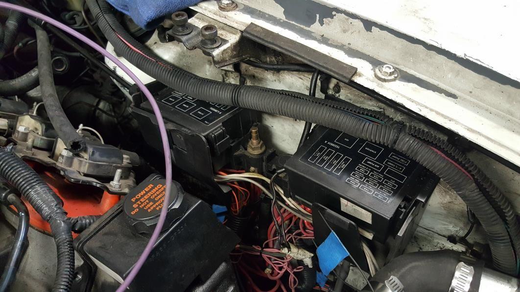
I put the GM fuse/relay box in the driver's side front of the engine bay, the same basic place it goes for the f-body.
ECU & Gauge Wiring
------------------
I found most of what I needed to know about the wire harness issues here: http://www.lt1swap.com/98-02_ls1.htm
I modified the FBody Wire Harness and did the programming changes myself. A harnesses terminated to your preferences can also be bought and programming paid for, probably for less than it cost me for the tools to do the programming but I like doing it myself.
I put the computer where the Porsche overflow tank was previously located. The FBody harness came up a few inches short of having it work well inside the passenger's footwell.
I removed wires/fuses and relays I decided not to use. The basic process was hook up everything I wanted to the motor then chase remaining wires on the schematics and decide what to do with them.
I decided to have the GM computer run the fuel pump.
The Porsche Wiring controls the AC and Starter.
I deleted the EGR.
I don't yet have a vehicle speed sensor but will probably do one eventually.
I bought a 'porsche 14 pin connector' for the connections that go to the factory gauges, AC controls, starter control. Search for them on e-bay, not hard to find.
14 Pin Connector Items:
Water Temp VDO A2C59517248S (from jegs) temperature
sender, connect to pin 3. The sensor will thread into an unused port in the back of the passenger's side cylinder head. Oil Pressure 30 ohms in series from stock sender to pin 4
Reads low but is proportional. Reads in the range 1 to 3.5 on the factory gauge.
Starter Pin 14 to the starter solenoid.
Tach:
4.7k ohm in series to green wire in the blue connector that is near the 14 pin connector under the hood.
Computer Programming
--------------------
I bought HP Tuners. Programming changes were small. In addition to the tach setting, I disabled the vehicle security system and put in the right volumetric efficiency table for the LS6 (my computer was programmed for an LS1). Hint, to disable the VATS you have to also download the tune even though there is a separate download option for changing the VATS...
For the tach, set engine/general/tach resolution high and resolution low both to 3.
Renegade Hybrids Basic Kit Notes
------------------------
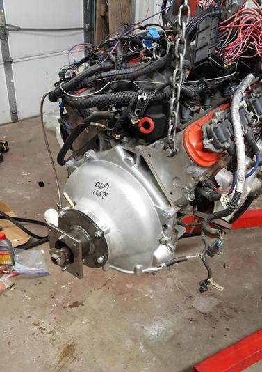
Their torque tube coupler could really use an access hole for the drive shaft coupler forward pinch bolt. It would make engine in/out MUCH easier. Without that hole the k-member should probably be unbolted and lowered to help get the engine in.
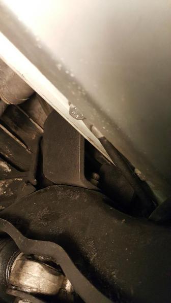
New holes are needed in the K-Member for the Engine Mounts. The mounts need to be oriented so that the 90 degree bend in the bracket is aft. The new holes in the k-member are about 1.5" inches outboardboard of the factory engine mount holes. I set the engine down on the mounts to figure out where they needed to be.
The clutch fittings for hose from the master to the slave would NOT go on the master cylinder if it was bolted in place. I cross threaded and ruined one clutch master/to cluch line fitting trying. Once in place they clear. A hole in the fender in just the right spot makes tightening the master cylinder hydraulic line MUCH easier.
I was not able to push fluid up from the bottom through the bleeder to get the air bubbles out. To bleed it I applied air pressure to the master and open the bleed port. I used regulated air from my compressor, I bought an extra lid for the brake fluid reservoir and put a barbed fitting in the center of it. I used a new Porsche 928 master, I modified the piston inside of it slightly so it would push more fluid. I cut 0.3" off the stem that limits its travel.
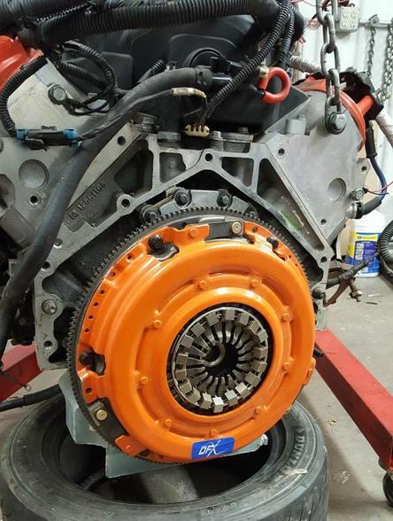
The clutch slave is fixed to the bell housing and has a travel limit that is very marginal to release the clutch. I used an FBody Flywheel that had been skimmed about 0.020". When I first put mine together it would not disengage because the slave was hitting end of travel. A 0.060" clutch slave shim fixed it for me.
Wish I found this before I put the clutch together!
1) Measurement "A" is the distance between the surface of the bellhousing that meets the transmission to the tip of the pressure plate fingers. To get an accurate measurement, the clutch must be torqued properly.
2) Measurement "B" is the distance between the throwout bearing surface to the transmission surface that meets the bellhousing. To get an accurate measurement, the slave spring must be removed and the bearing must be fully seated at the bottom of it's travel; resting on the slave's base.
Once you've got your two measurements, make sure that measurement "B" is ~3/16" to 1/8" LESS than measurement "A". If you come up with more than 1/8", add an appropriately sized shim between the slave cylinder and the transmission in order to get the measurements where they need to be.
Your “A minus B” measurement should be 0.125 to 0.200 for adequate bearing travel and to allow for clutch wear. If there is no difference between the two measurements, or if "B" is greater than "A", there could be a problem with clutch engagement which could result in premature clutch slip and eventually a total failure.
Remote Oil Filter
-----------------
I used braided AN line because I already had it. If I had it to do again I'd have used push lok. I did 90 degree adapters to hook to the block. Straight through at the filter.
The oil filter housing is bolted to the frame with long bolts that go all the way through the frame rails.
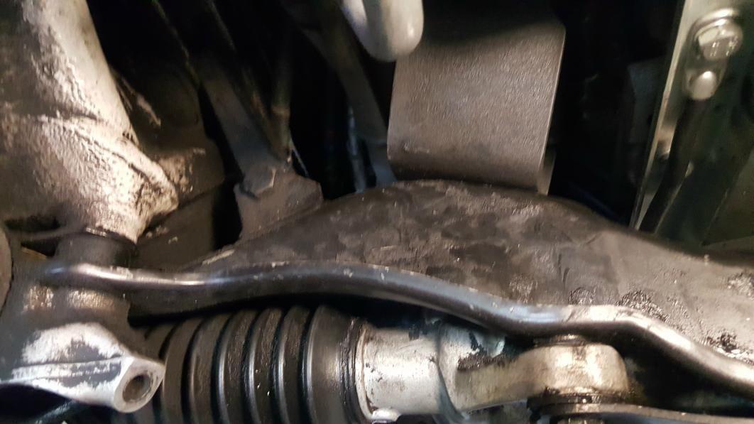
Sway Bar
--------
My sway bar didn't quite clear the renegade oil pan. I was able to use a harbor freight 20 ton press to tweak it and get it to fit.
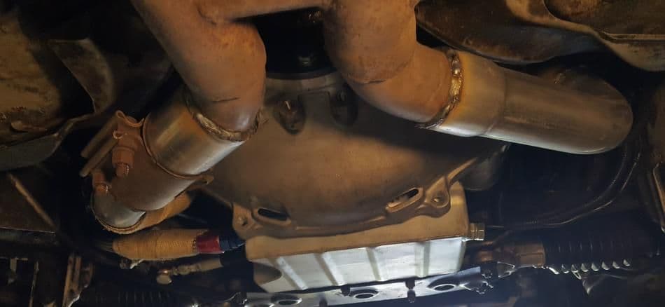
Exhaust
-------
I used stock FBody headers. I bought flanges that bolt to them on e-bay. They are an odd shape and not the same on both sides. I took those and an O2 bung to the muffler shop and had them bridge the gap back to the factory cat back. There is a coupler on one side to make it easier to take appart if needed.
Heat shielding is needed around the starter, without any heat shield the headers are too close and get it so hot the solenoid won't doesn't want to work.
MAF
----
GM Maf's don't seem to like to sit unused and unsealed. I had to replace the one that came with my donor to get it to run right.
Cooling System
--------------
Radiator
Northern Radiator # 209628
Radiator Cap - Northern Z19200
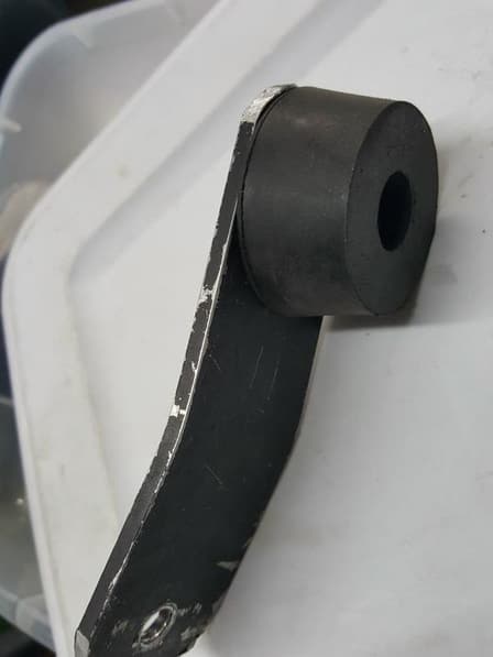
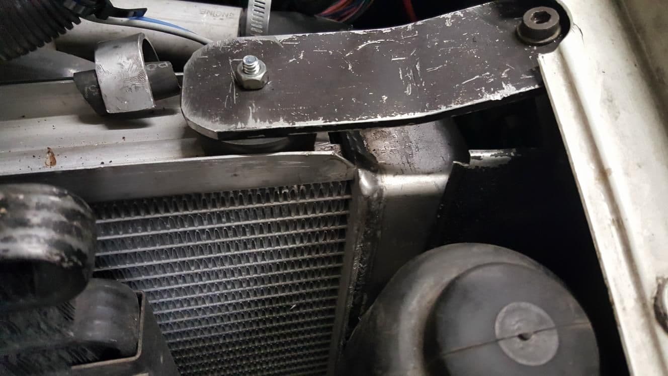
Radiator Mounts
I made them out of plate aluminum and rubber stoppers.
Counter bore the rubber stoppers and bolt to the plate parts.
(Pictures)
Radiator Hoses
Camaro SS Power Steering Cooler in line with upper hose.
One upper hose is stock, engine to power steering cooler.
From the other end of the cooler to the radiator is a segment from
1995 bmw 525i upper radiator hose.
The lower radiator hose is Gates 21717
Radiator Fans
Ford Contour fan (95-00 V6) shroud & fans
electrical connectors for it were available on ebay
I made some aluminum brackets from flat stock to hang
the shroud from 3 points instead of 1.
Zip ties at the bottom of the fan shroud.
Heater Core Connections
FOUR SEASONS 74781 Heater Control Valve
5/8" hose 3' length
3/4" hose 6' length
� to 5/8 hose line reducer, Gates 28611
Overflow Tank
Upper connection, to steam vent at front of cylinder head
Drain line, T's into lowest point in water pump hose.
Mounts to passenger's side cylinder head using simple aluminum
angle bracket.
Power Steering
--------------
Stock GM power steering pump.
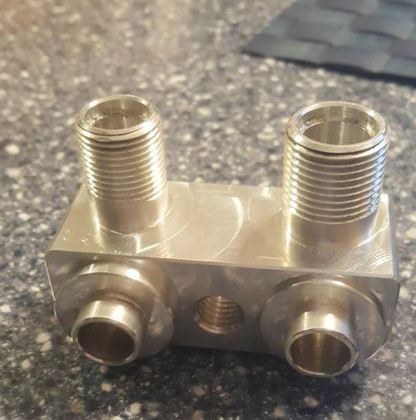
High Pressure Line & Fittings
Have 36" 3/8 jic end hose made one 90 degree end, one straight through
Low pressure Line & Fittings
3/8" power sterring hose, low pressure, 6'
1ea Russell part# 648060 (attaches to GM PS pump)
1ea m14 x 1.5 banjo and bolt to -6an (attaches to 928 steering rack)
1ea m14 x 1.5 banjo to 3/8 barb
There is a tool for removing and installing power steering pump pulleys. It can be had at Harbor Freight or borrowed from most car parts stores. You need it just to install or remove the power steering pump.
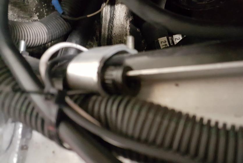
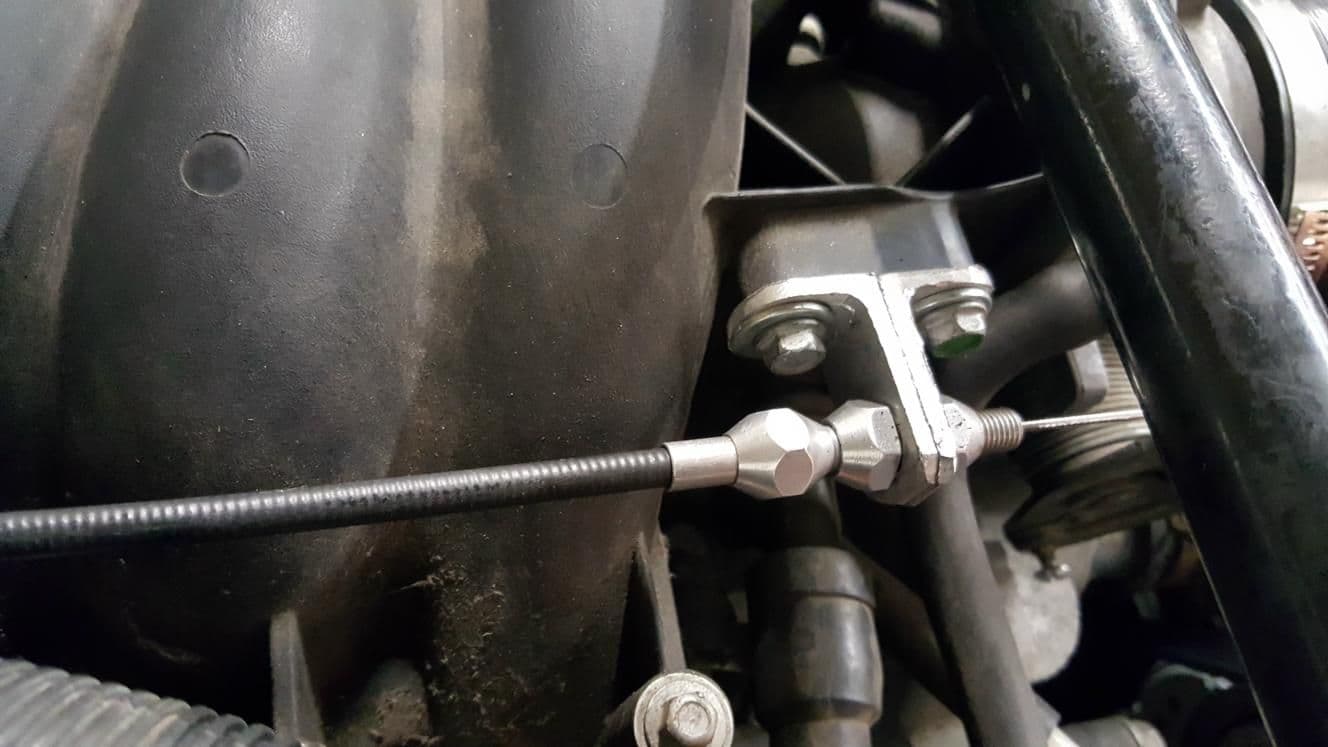
Throttle Cable
--------------
I used this:
Lokar TC-1000U36 36" Universal Throttle Cable
but doing it again I'd use this:
Lokar TC-1000LS1 Universal LS1/350 Ramjet Cable, 36"
I cut the throttle body end off and modified a barrel
I got in a pack of assorted cable ends through Amazon.
I Modified the pedal assembly with a dremel to take
the tip down to the diameter of the shaft where the stock
cable attaches and cut a notch for the circlip.
I drilled out the end hole through the clevis slightly
to match the rod on the accelerator pedal.
Two chunks of aluminum angle made the bracket
that mounts the cable.
Fuel Lines/Pressure Regulator
------------------------------
Porsche Hard Line Ends
Fragola 491971-BL Size (-6) x 16mm x 1.5 O-Ring Female Adapter Fitting
Russell 670530 (-6 AN Flare to 16mmx1.5 Male)
Fuel Rail Push Fitting
LS1 LS2 LS6 LS3 LS7 Fuel Rail Adapter Fitting FEED AN 6 PUSH ON BLACK
Regulator/Filter
New Corvette LS1 Full Flow Fuel Filter/Regulator & Fittings, In-Line, Full Flow, 58 PSI
Push Lock Ends
PRE-20600 -6 AN Push Lock Straight Swivel Hose End Red & Blue Anodized Loc Lok
Push Lock Hose
Six feet - GAT Gates Push Lock Hose 3/8 for AN -6 Fittings
With a heat gun from harbor freight and a bit of lube the fuel lines went together extremely easily!
Intake
------
4" to 3.5" silicone coupler (intake to MAF)
3.5" right angle silicone elbow
Drilled hole in the elbow and silicone
glued in the intake temperature sensor.
3.5" OD aluminum tube about 1.5" long
Short 3.5" inlet diameter cone air filter.
Weight
---------
With 1/4 tank of gas, no driver
Original: 3131
After the Swap: 3070
I cut it in half, so it can be installed pointing DOWN instead of up, get a
longer bolt and a plate to put across the top of the halves...
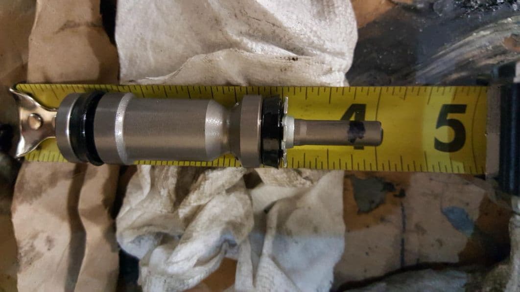
To get the compressor to work with the rest of the 928 AC system a small modification was needed:
------------------------------------------------------------------
Pull the circlip off the bottom and pull the control valve out.
Weld the valve end shut or jb weld the valve end shut.
Reinstall...
Hoses:
High Pressure Side
---------------------
(from the 'd' fitting on the compressor, smaller diamter)
3/4-16 o-ring fitting to #8 barrier hose crimp fitting
#8 barrier hose crimp fitting.
#8 barrier hose beadlock splice with 13mm r134a charge port
#8 barrier hose
#8 barrier 90 degree beadlock splice connector
3/4-16 o-ring fitting to #8 barrier hose crimp fitting
Low Pressure Side
----------------------------
7/8-14 o-ring fitting straight to #10 barrier hose beadlock fitting
#10 barrier hose
#10 beadlock splice with 16mm r134a charge port to #10 beadlock
Last few inches of the original hose connects to pipe on frame rail...
A local O'Reilly Auto Parts store crimped the fittings for me on the hoses for free.

 11-22-2018, 08:46 PM