When you click on links to various merchants on this site and make a purchase, this can result in this site earning a commission. Affiliate programs and affiliations include, but are not limited to, the eBay Partner Network.
One might be puzzled at this point by noticing that the blocks as formed above do not appear to "match." That is, they do not appear to be opposite sides of forms that might squeeze something inbetween to a different shape. That is because I am designing these forming dies to utilize a process that may be known as, but at least that I call, "stretch forming." In this process what is needed is not an exact pair of forms for both the inside and outside of the object to be formed, but rather, in most cases, only the exact shape, usually in a positive form, to be pressed inside the opposite form that needs only to be the perimiter shape, and not the exact opposite of the positive form. The sheet metal will simply follow the positive form and have its perimiter shaped by the female opening rather than the female shape. There will be a few places in these forms where both the female and male shapes are formed opposite each other, but most of it will be simply sheet metal stretched over a male form.
What that means for this project is, for the most part, that I need only to form positive shapes for much of it to be pressed into opposite openings that do not need to have any more shape than the edge of the opening itself. In other words I will need to press sheet metal into an opening with a male die and the female die needs only the opening or perimiter shape, and the depth of it needs only to be enough to clear the male die and the material thickness. In some cases that also means that I will be pressing two edges against each other with substantial clearance between them which results it the material simply being stretched straight from one edge to the other, which ends up in the desired shape for the work piece.
Last edited by Jerry Feather; 01-06-2020 at 09:20 AM.
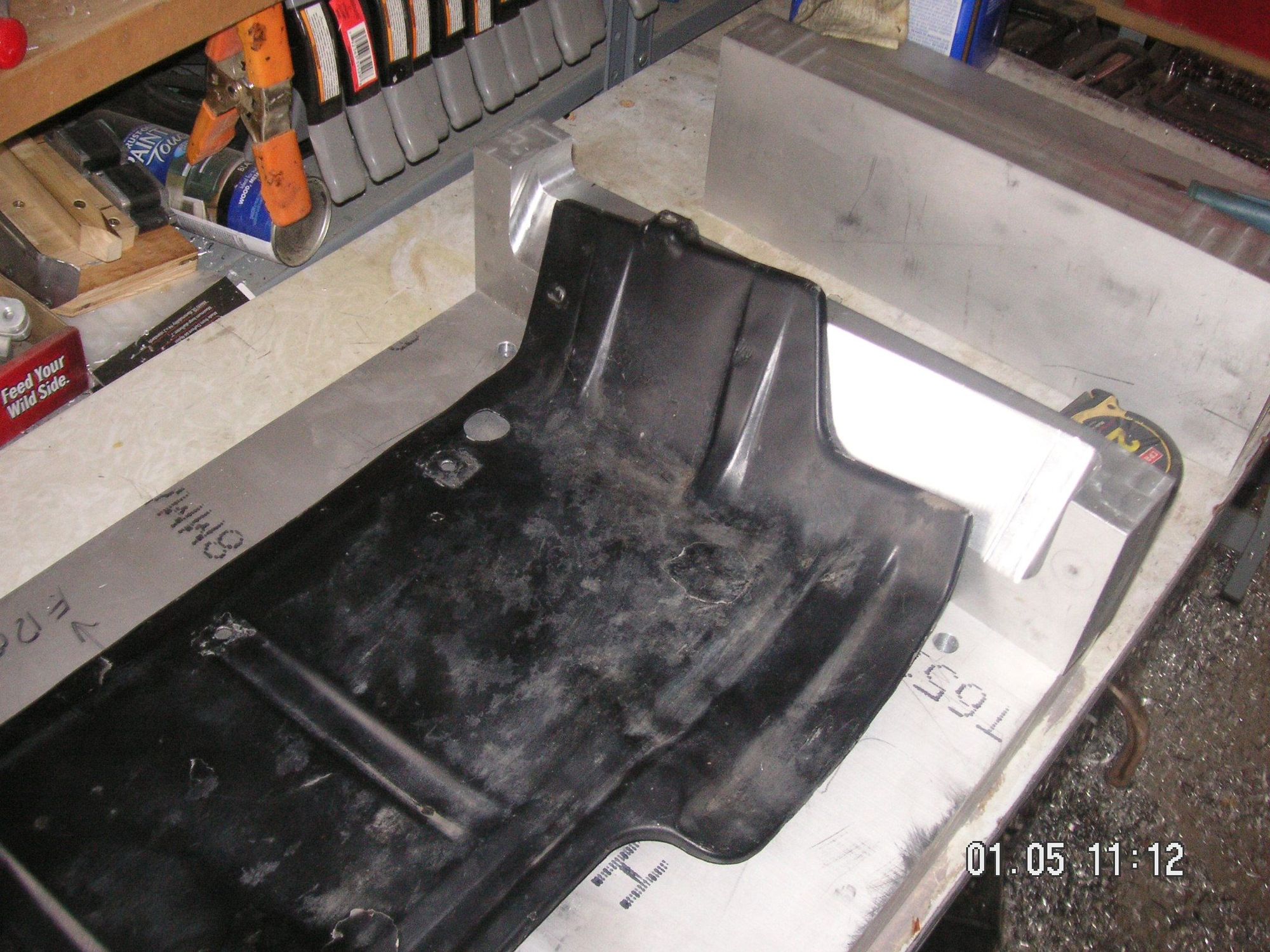
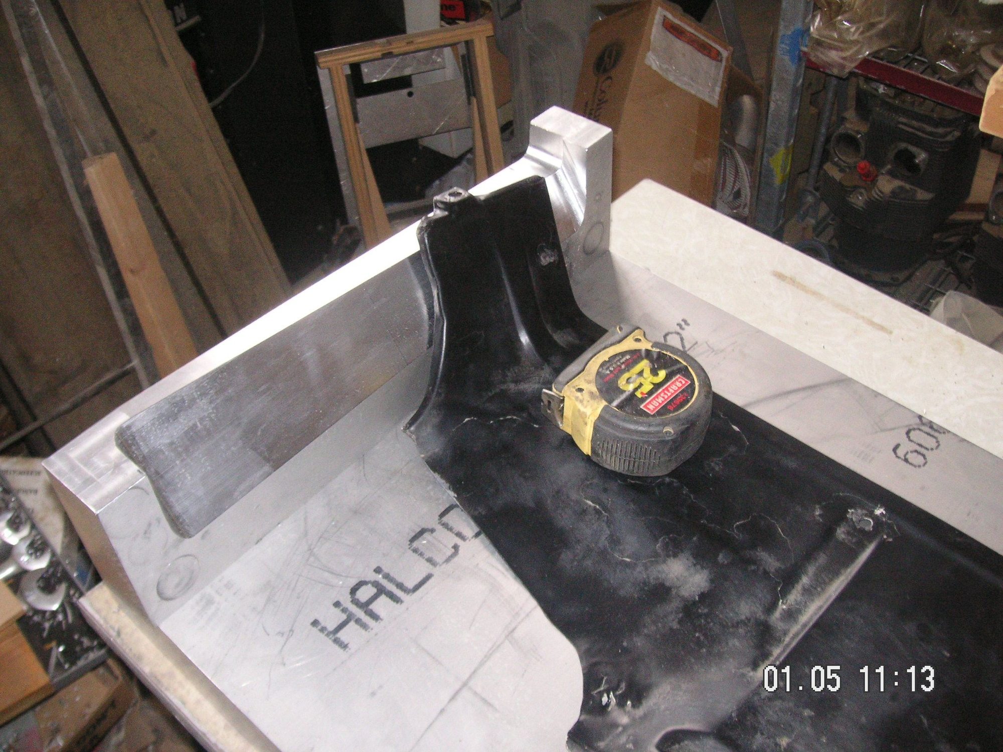
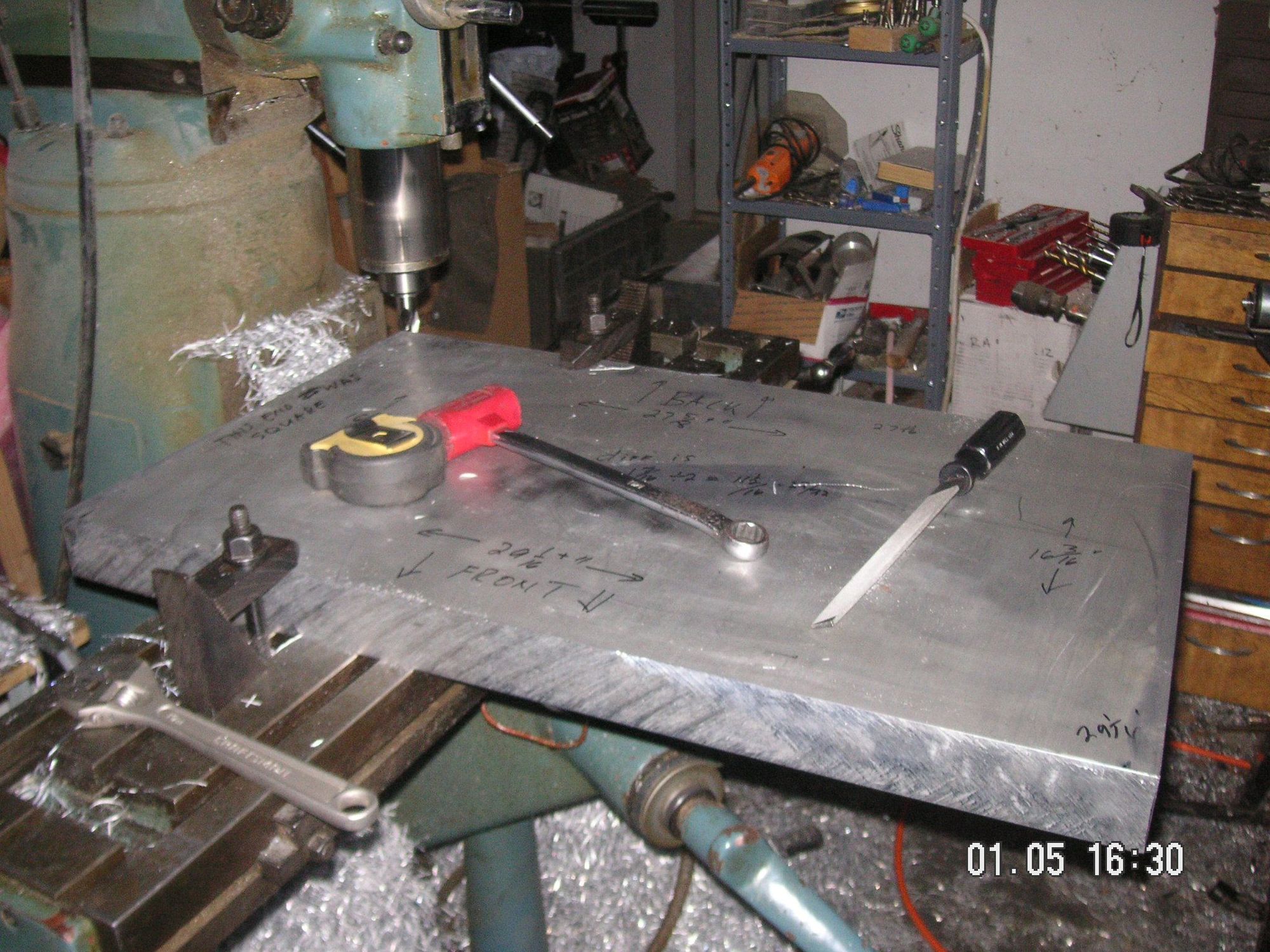
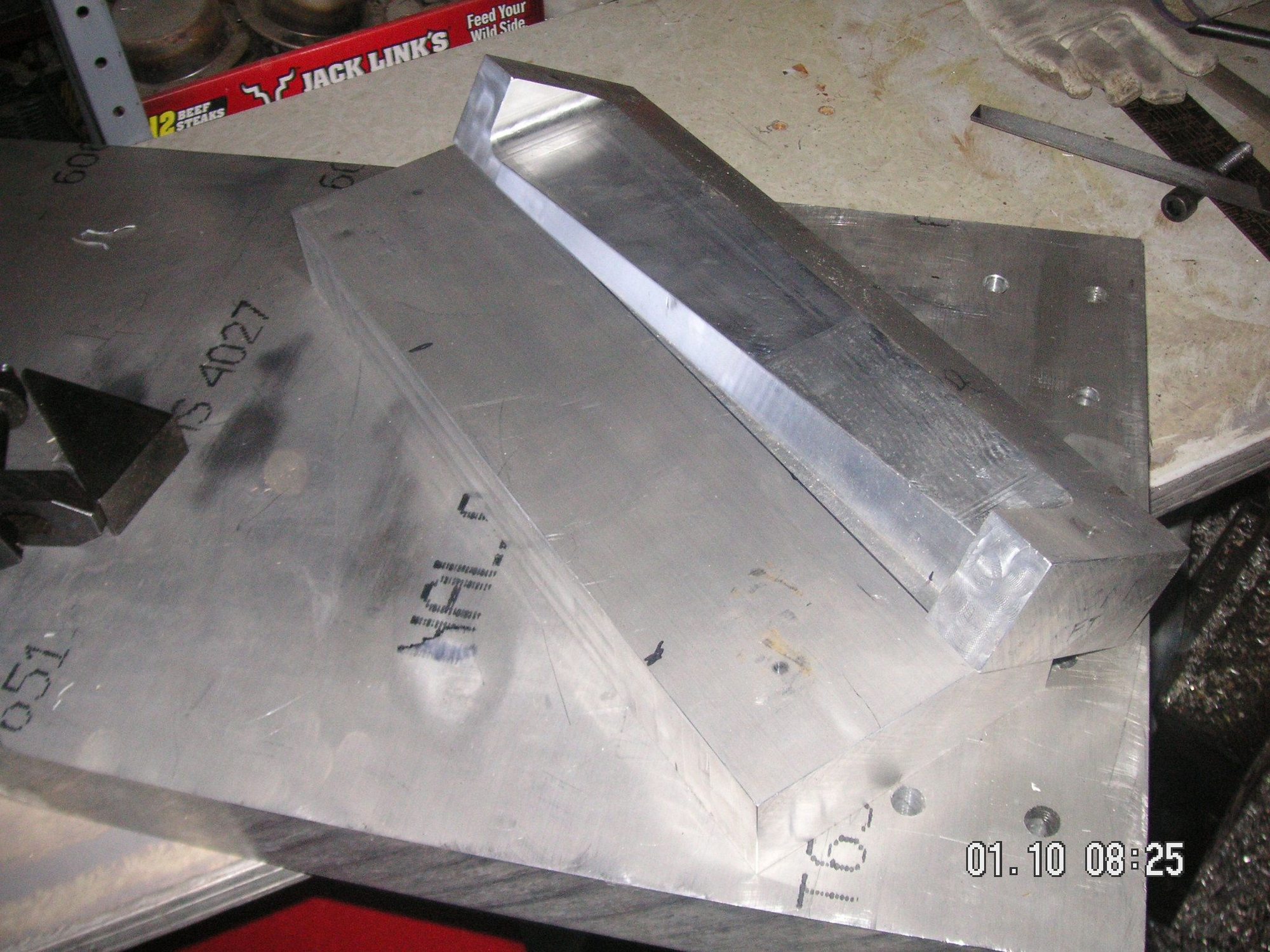
This morning I was able to get the base form, about 200 pounds, up onto a work table I have fashioned for this project and then I set the two female end pieces on it with two of the five bolts I have provided for each end. I did some rough placement of my original pan on it and with the male dies, on one end, and took some pictures so you can see at this point kind of where I am going with this.
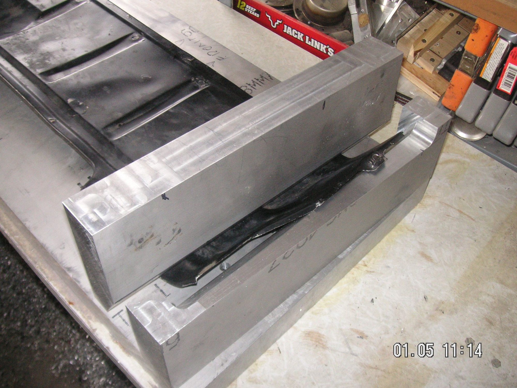
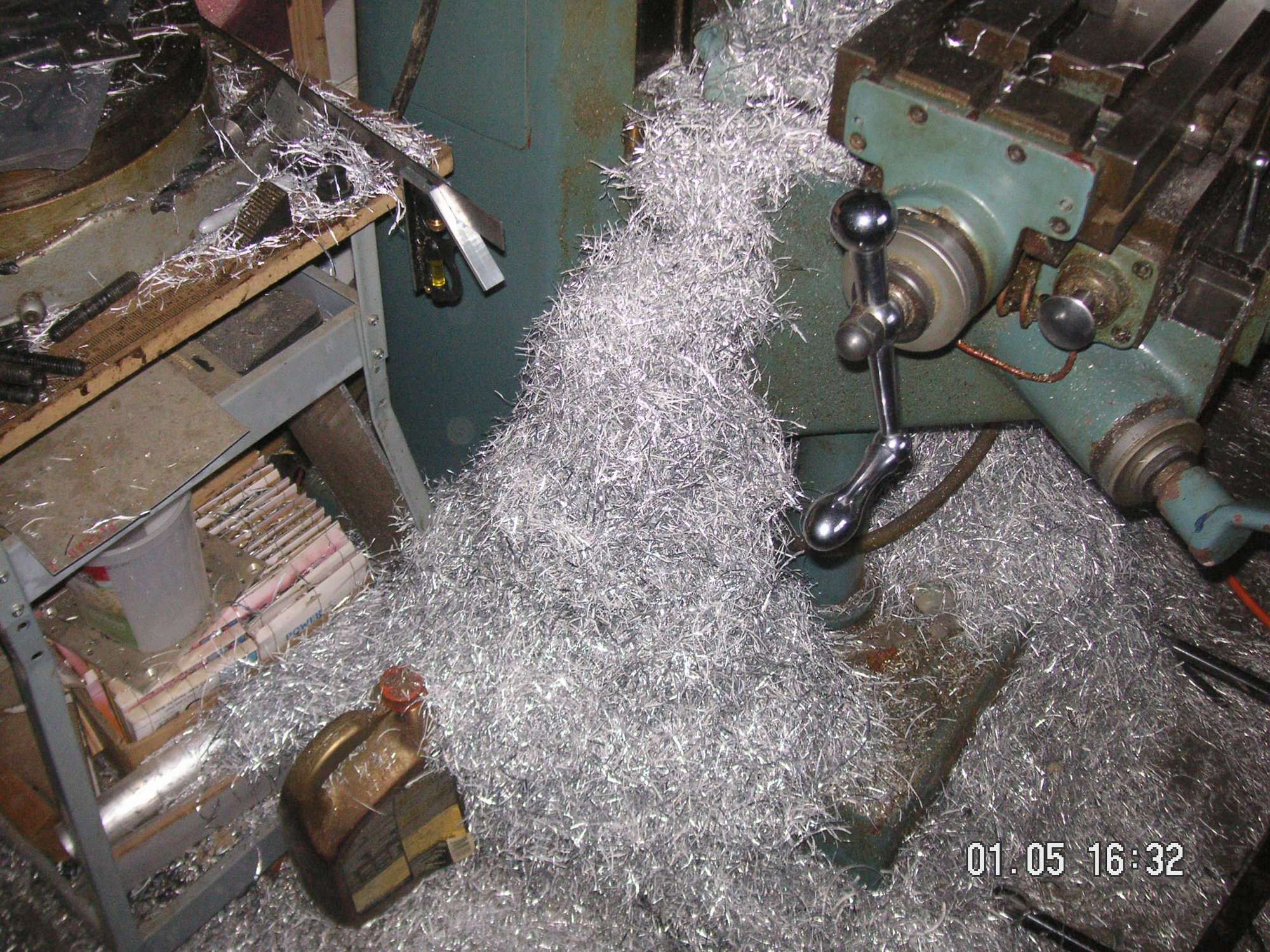
Then I was able to retrieve the center male form piece from out in the snow where I had unloaded it and brought it into the shop to kind of warm up and defrost so I can lay out the cuts to taper the ends of it to match the other dies.
Last edited by Jerry Feather; 01-06-2020 at 09:23 AM.
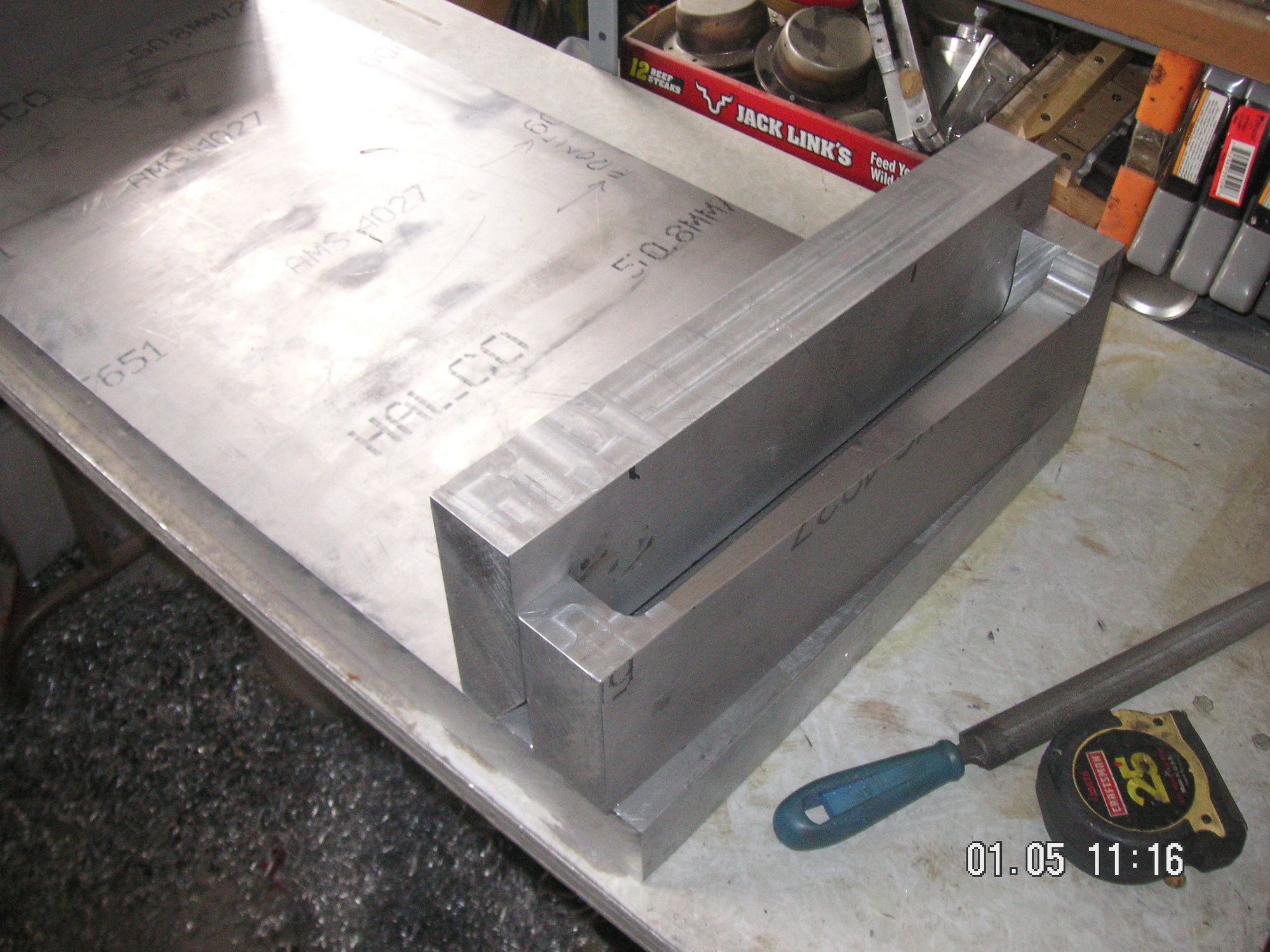
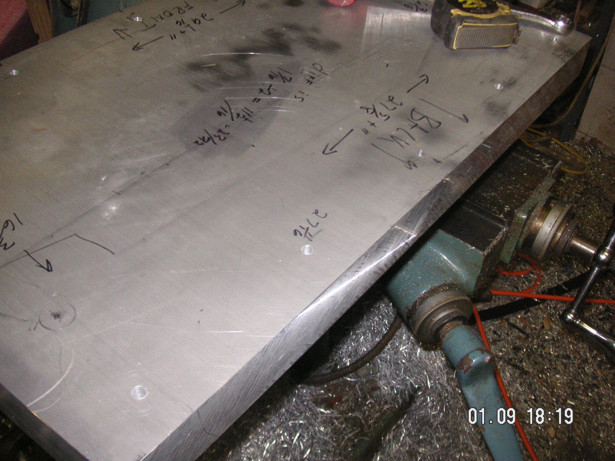
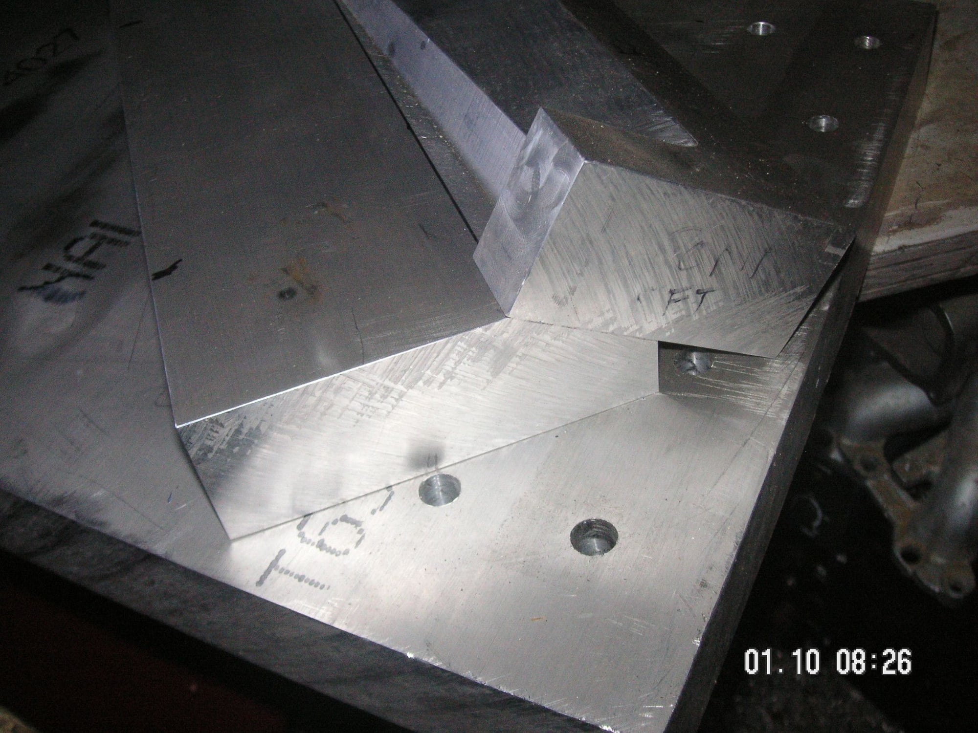
I got the center piece thawed out and hefted it onto the mill table. After some careful measurements of the space it needs to fit in, giving allowance for work piece material thickness, particularly at the ends, I transferred the measurements to the center piece and marked them for milling. Then I carefully located the piece on the table and milled each end to the correct taper. I think I have it just about exact. I can't take it off the mill and try to fit it on the other base pieces, mainly because I don't think my work table will hold it all up.
I also put two pieces of stiff wire into the upper mounting holes in my S4 up on blocks (the radical custom project) and hung them straight down, kind of like JP is planning with weighted strings, and found that they measure very close to the 35 1/2 inch measurement I had found in my original pan. I am comfortable continuing to work with that measurment between the holes in forming any new pan with my hoped-to-be forming dies.
Now I have another whole Xmas tree-like pile of shavings to deal with. Maybe I can devise some kind of decoration out of it all.
Next, before I take this last piece out of the mill I am going to drill a row of holes along the front and back of it to use as alignment and guides for the pressing of pans and also to bolt the center piece down on the work piece to form the ends. I haven't yet figured out how best to locate all those holes so that they will match between pieces since I think both large pieces of aluminum in the mill is more than it can take, weight wise, and the best way to drill them would be together. I think I will have to resort to my skill as a precision machinist and drill them in each piece separately. We will see.
Last edited by Jerry Feather; 01-05-2020 at 09:05 PM.
Reason: typos
wow making your own aluminum press mold , is there anything you cannot do.....
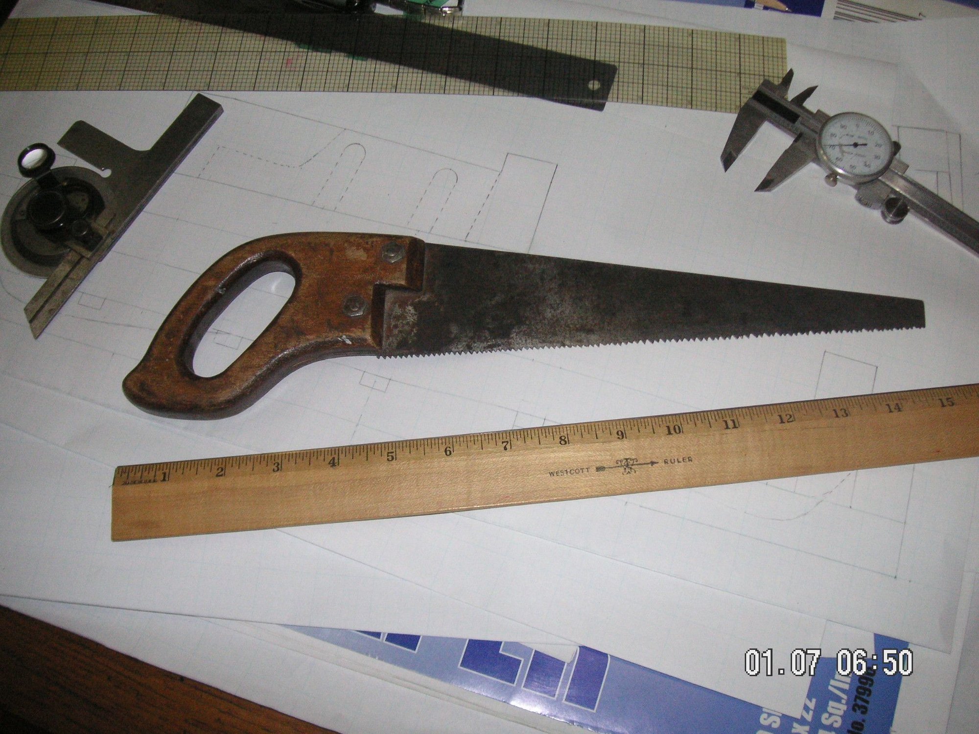
Andy, I think I was inspired at about age 5, by my Maternal Grand Father, to find ways to make things for myself rather than going to the store to try to buy something. He fabricated for me a small child-size hand saw out of a much larger one he found in our backyard. I still have it. It is probably my most cherished possession. Anywav, based on that inspiration, over the years I have taught myself and been taught how to work in many mediums and many different materials. My Mother taught me how to sew. My Father taught me to be a perfectionist. I have had formal education in wood working, metal working, welding and forging, and precision machining. I have never worked in any of those enviornments, but rather I became an attorney, which is, from a mental standpoint, very similar to fabricating various things. Actually it all boils down to simply problem solving.
I learned most of my fabricating skills by reading, watching, listening, and then doing. The real trick to most of it is to have the necessary machinery and tools to get the job done. So, I have an extensively equipt shop (or shops) and have more different types of machines and tools than anyone else you might know.
Here is a picture of my inspiration tool.
Last edited by Jerry Feather; 04-28-2020 at 01:44 PM.
I didn't work out in the shop any yesterday or today, but I am working on the design of some of the details that will take quite a bit of work even though pieces of them are pretty small, compared to these prior pieces of aluminum. I also have to design some bevel tooling to match the bevels milled on 4 of the prior pieces mainly so I can bolt them in the mill with the bevels flat toward the cutters. You will be able to see what I mean when I get to it and to use them.
I have also figured out how best to make the 10 holes for the guide and hold-down bolts that go along the front and back of the basic forms. I'm going to precision drill all of them in the male center form piece in the mill with a 5/16 inch bit, then I'll locate that piece onto the basic base form member and clamp then together, and by hand drill guide holes into but not through the base piece. Then I'll put the base piece in the mill and kind of precision drill the holes to finish, using the hand drilled holes as guides for location, then open them up the the minor size for the half inch tap and tap them, then I'll drill the male piece holes the the half inch final size.
Then It looks like I have made a deal to purchase the 50 ton press I was looking at online. I'll probably go pick it up in the next couple of weeks. That makes me a bit more excited about the prospects for this project.
Last edited by Jerry Feather; 06-09-2020 at 10:29 AM.
Jerry,
Good progress! I did a drop and measure today, and got 35.375", give or take a 1/16", so thats very close to your 35.5" - certainly workable in light alloy sheet.
jp 83 Euro S AT 57k
JP, thanks for confirming the mounting hole measurments.
I got to work on the dies a little today after I got home from the office. I had been hoping to work on some of the details in the end pieces, but then remembered that with the big center form piece still in the mill I needed to get the 10 registration/guide bolt holes started. So I set the piece up on the mill table and drilled five pilot holes along each side, the front and back, of it. They are spaced 6 inches apart. Next I'll put the piece onto the bigger base piece and carefully locate it in its determined position and then I'll drill starter holes through these 10 holes and into the base piece with a hand drill and this 5/16 inch bit. With those started I'll be able to put the big piece in the mill and then drill these new pilot holes all the way through then redrill them to the minor size for the half inch bolt threads. Then I'll have to put the top center piece back in the mill and redrill all 10 if its holes to the half inch bolt size. It ought to be fairly simple but gets kind of complicated.
I also have been working on the details and procedure to fab and mount the three little pieces that will form the kind of corner stiffening ridges. They wont be in exactly the same place as the factory ones, mainly because I didn't plan my 10 mounting holes for holding the end pieces onto the base very well, and a couple of those will interfer with these detail pieces unless I move them a little. Not a big deal in the final analysis.
Last edited by Jerry Feather; 06-09-2020 at 10:31 AM.
One of the things I have been thinking I'll need is to devise a way to present the beveled surfaces of all 4 of the end pieces to the mill cutter in a level position in order to cut some of the details needed in those surfaces. I had been thinking that I will need to machine some tooling with the bevel on it to put under the end pieces so that the bevel is level. Then I was having some difficulty deciding just how to do that and what to do it with. Then, last night it occurred to me that I already have just what will be needed, and that is the two inner end forming pieces that already have the bevel on them and that they can be used to hold the other pieces, and each other, level. DUH!
The only issue now, and would be in either case, is how to hold them together under the clamping force without them slipping down the bevel under the force. I will give it a try when I get there.
Last edited by Jerry Feather; 11-24-2020 at 10:46 AM.
The only issue now, and would be in either case, is how to hold them together under the clamping force withough them slipping down the bevel under the force. I will give it a try when I get there.
Jerry, You already know where any drilled holes are going to go. Could you hold the piece in place with bolts through the piece into tapped holes in the mold?
Jerry, You already know where any drilled holes are going to go. Could you hold the piece in place with bolts through the piece into tapped holes in the mold?
That is good thinking, John, mainly because it kind of goes along with some of my own. My thought is, if these mold pieces have a tendency to slip apart along the bevel I could very well simply bolt them together to keep that from happening. The only problem with that is that there may need to be a lot of different sets of holes since these pieces are going to be shuffeled back and forth a yet to be determined number of times and I'm not sure I want to go to the effort to either drill several different matching sets of holes or to figure out how to precision drill a limited number of holes that match up with any combination of mold pieces. I guess I'll work that out when I get to it. Actually, I may get to keep these from slipping along the slopes by some form of simple sideways clamping.
Last edited by Jerry Feather; 01-21-2020 at 08:22 PM.
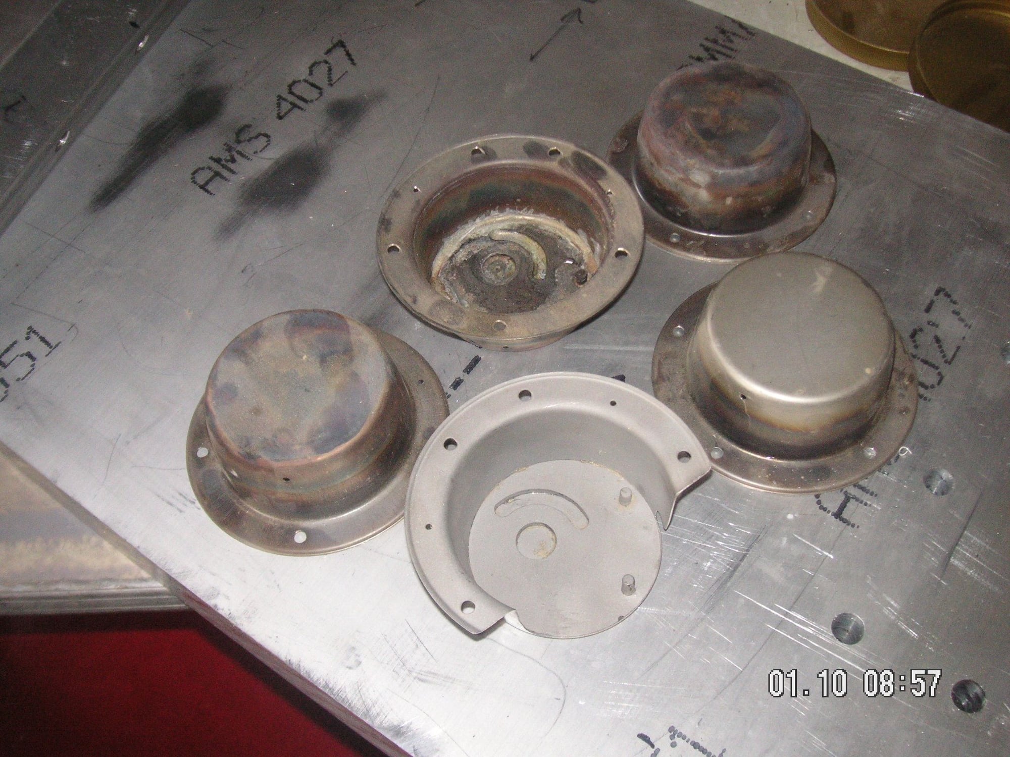
I know there are skeptics out there who are doubtful about my ability to go from "plastic man" to "metal man," as I mentioned, I think, in the other thread before I started this one, and I think I am one of you or them, because I almost always have some doubts about my ability to end up in any one of my projects with success. Nevertheless, I noticed in one of the pictures above a cardboard flat which contains the result of one of my former aviation metal forming endeavors.
I pulled the flat out and took a couple of pictures of what it contained, mainly a grouping of small metal cup-like items that I figured out how to form out of flat sheet stainless steel. These are for the Canopy latch for the Navion Aircraft, of which I have 2. The canopy latch housing has a tendency to crack in its original form and there is essentially no way to repair it. No one had ever been able to form a new housing except by welding one together out of pieces; so I decided that I would see if I could form some. It took quite a lot of trial and error, to the extent of about a bushel of failures, before I finally learned how to get it to form all the way without rupturing.
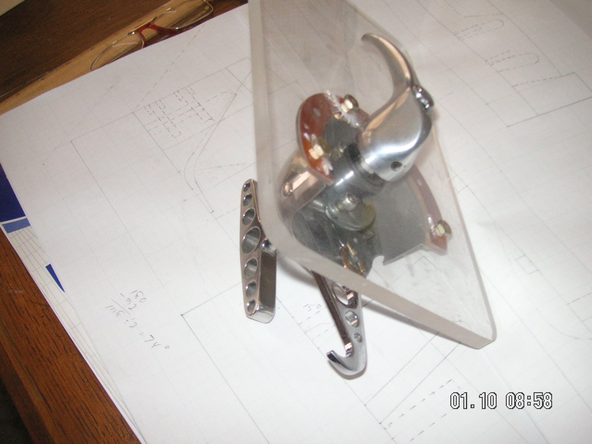
When I succeeded with the housing I then had my Son Tim, the Engineer, help me redesign the components inside to both beef it up and to get it to work like I think they had intended originally, but where they didn't quite make it. Here also is a picture of my final version of it all together. All of this I made except for the cast aluminum outside handle shown here.
Last edited by Jerry Feather; 01-21-2020 at 08:25 PM.
I don't know who's doubting you, but they shouldn't. I have a longstanding dream to learn some machining so these kinds of posts really help scratch that itch. Alas, this won't fit my car but I love that you're being so diligent about posting your progress and thinking about how to anticipate and tackle the manufacturing of the parts.

 01-05-2020, 01:23 PM