When you click on links to various merchants on this site and make a purchase, this can result in this site earning a commission. Affiliate programs and affiliations include, but are not limited to, the eBay Partner Network.
I’ve been nursing 2nd gear on my 1983 5-speed for quite some time now. Upshifts into 2nd in particular have been just a little too soft and I could feel a little notchiness going into gear sometimes. I adopted a few workarounds to minimize shifting into 2nd and while it hasn’t gotten any worse in a long time, a transmission rebuild has been on my list of things to do. Frankly, I’m getting tired of having to baby it, and the coronavirus has given me the chance to fix it. (For more of my two-year-long renovation project, see here: https://rennlist.com/forums/928-foru...oses-83-a.html)
There was one more thing that was bothering me: the reverse lockout broke when the car was just a few years old. I still remember when it stopped working… and that was in 1990!! Again, not too big a deal, and somehow I’ve never once shifted accidentally from first into reverse, but I’ve really missed that solid feeling knowing I can shift from 1st to 2nd without worry.
My goal is to perform the "gold standard" of transmission rebuilds and have it last another 100K plus miles -- in fact, just as long as a brand new transmission. That means I’ll prophylactically replace a bunch of items to "reset the clock" and make my transmission virtually brand new, and that includes as starters all bearings and races*, all syncros, all the stones/stops/brake bands, and at least two of the three shift rings (we’ll see on the 1st/R), plus a bunch of miscellaneous items (more below). *The only exception is the main pinion bearing which I’ve never seen mentioned as being a problem, so I’ll inspect it when I get there and evaluate. And the best part is that you can replace ALL those parts, end up with a better result than a typical rebuilder would do, and still end up paying less overall!!
One of the biggest decisions in any rebuild is deciding what parts to replace. This is a classic case of balancing cost of parts versus a bunch of other factors including, not least, the extreme amount of labor it takes to get the transmission out of the car, disassembled, reassembled, and re-installed. However, one of the things I learned in this project is that you should treat it like any other "refresh" project. If you're refreshing your front suspension with 100K plus original miles, it's already a no-brainer that you'll need shocks, bushings, bearings, and tie rods, and maybe some other things as well depending on what you find and how thorough you want to be. The transmission is no different -- it's going to need all bearings, races, syncros, and shift rings, and beyond that will depend on your budget and whether anything is clearly broken or worn.
One of the advantages of doing the rebuild yourself (besides saving money) is that you can do your own homework and make your own informed choices about what to replace, as opposed to taking it to a shop where you either aren't involved in those choices or the wrong choices are made. Some shops, even so-called "experts," apparently neglect to change many of the critical wear components. Shift rings in particular are fairly expensive, so they seem to be the main way that some shops save money by trying to re-use old and partially worn ones. (Shift rings slide frictionally against the syncro during every shift, and both wear out together, like brake pads and rotors). This includes so-called "flipping" of shift rings to trade one partially-worn surface (like 5th) to an even more worn surface (like 4th). To me, that's fine if you intentionally are trying to save money and are aware of the tradeoffs, but that's just it -- it's a tradeoff. If an expert passes that off as the gold standard then I'd find another expert. Not only will that never last as long, but you'd end up with a very different shift feeling on different gears depending the state of wear of the re-used parts. (You can see this yourself in one of my photos, later, that shows two old shift rings against a brand new one. There's a huge visible difference, even with my 4/5 ring which was working beautifully. You can also measure the huge difference with these parts versus new ones with the "height" test I show as well. My new 4/5 shift ring feels far better while driving than the old one. But I'm getting ahead of myself!) Flipping shift rings is exactly like "rebuilding" brakes by mixing and matching some old rotors with some different, old brake pads -- perhaps tossing in one new brake pad for good measure -- and calling it a day when the Frankenstein combination meets a certain minimum thickness. Sounds like an invitation to re-do the job as soon as the warranty expires.
This is precisely why you're better off doing this job yourself. Better to do it right the first time than have problems crop up ten or twenty or even thirty K down the road, caused by some rebuilder cheaping out or making the wrong choices (and when any warranty is long expired). I'd rather buy new parts now than have to pull the transmission out a few K or years down the road to change out a shift ring that the "expert" rebuilder decided was "good enough." Far better to do it yourself, and do it right, where you choose to make your own informed tradeoffs and can do a better job.
Anyway, the nice part about doing it yourself is that you can take all the money you might have paid someone else to do it, and instead put it towards more new parts... resulting in a better rebuild... and still come out ahead of the game! If you can take the transmission out of the car, you will be able to do the rebuild. There's no black magic here. Do your research like I did, check out my thread and my links, and judge for yourself.
Another goal is to get everything clean. As clean and sparkly as brand new. More on that later.
Beyond that, I must say the transmission has been a trooper… input bearing and other bearings do not make untoward sounds and all the other syncros work great. In fact, one thing I’m looking forward to in this rebuild is investigating how little worn the 1st gear syncro and shift ring is likely to be. I have never once downshifted into first while rolling, and there’s no syncro to wear for R, so that 1st syncro and shift ring should be more or less brand new. (On the ’83 and up transmissions the 1/R shift ring can’t be flipped as on the earlier transmissions).
As a note on syncros (and shift rings, though I’ll often refer to the system as “syncros”), which I’ll talk much more about later, the G28.08 uses the “Porsche” style syncros which are much different than the 85-up Borg Warner style. Although there is not a great deal of information on rebuilding any of the transmissions on this forum, there seems to be a particular lack of information about the early transmissions. All is not lost, however, as it turns out that the 911’s “915” transmission uses virtually identical syncros – in fact, many of our syncro part numbers start with 915 – and as luck would have it, there are a number of rebuild threads on Pelican which are extremely informative when it comes to these syncros (and transmission rebuild tips in particular). I spent a significant amount of time reading everything I could find on the Internet about rebuilding the 915 transmissions, about our G28 transmissions, and even about rebuilding American transmissions, prior to even starting work on the car. I’ll link to some of the most helpful threads and videos, as well as other useful information I found along the way, in a later post. Fun fact: Porsche apparently had a good licensing business going for a while with this syncro design and licensed it to other European makers such as Alfa Romeo in the 60s and 70s.
I’ve never removed the transmission, axles, or the rear crossmember from my car, and I’ve certainly never worked on a 928 transmission before, so I’m looking forward to seeing how “interesting” that turns out to be. I’ll be following the Workshop Manual (WSM). Please join me in diving in!! If I get anything wrong, no flames, but constructive additions are ALWAYS welcomed.
Caveat: I’m no expert, don’t take my word for it but consult and follow the WSM, and I am only sharing my experience and what I’ve learned for informational and entertainment purposes. Removing, working on, and reinstalling the transmission can cause property damage, serious bodily harm or death. And following my (possibly incorrect) procedures could result in a broken transmission, an accident, or worse. I make no representations or warranties of any kind including but not limited to those of safety, correctness, or fitness of purpose. Use any information contained herein strictly at your own risk.
I found removal and rebuilding of the transmission to require only a few “special” tools (and my definition of “special” means that I didn’t already have it, and I by no means make any claims to having the most complete garage shop). For the most part, standard hand tools and measuring devices that are part and parcel with doing almost any job on the 928 are all that is needed, which includes good digital torque wrenches. I also do not have a lift, or even lift bars, and found that not to be an issue. I purchased the following items:
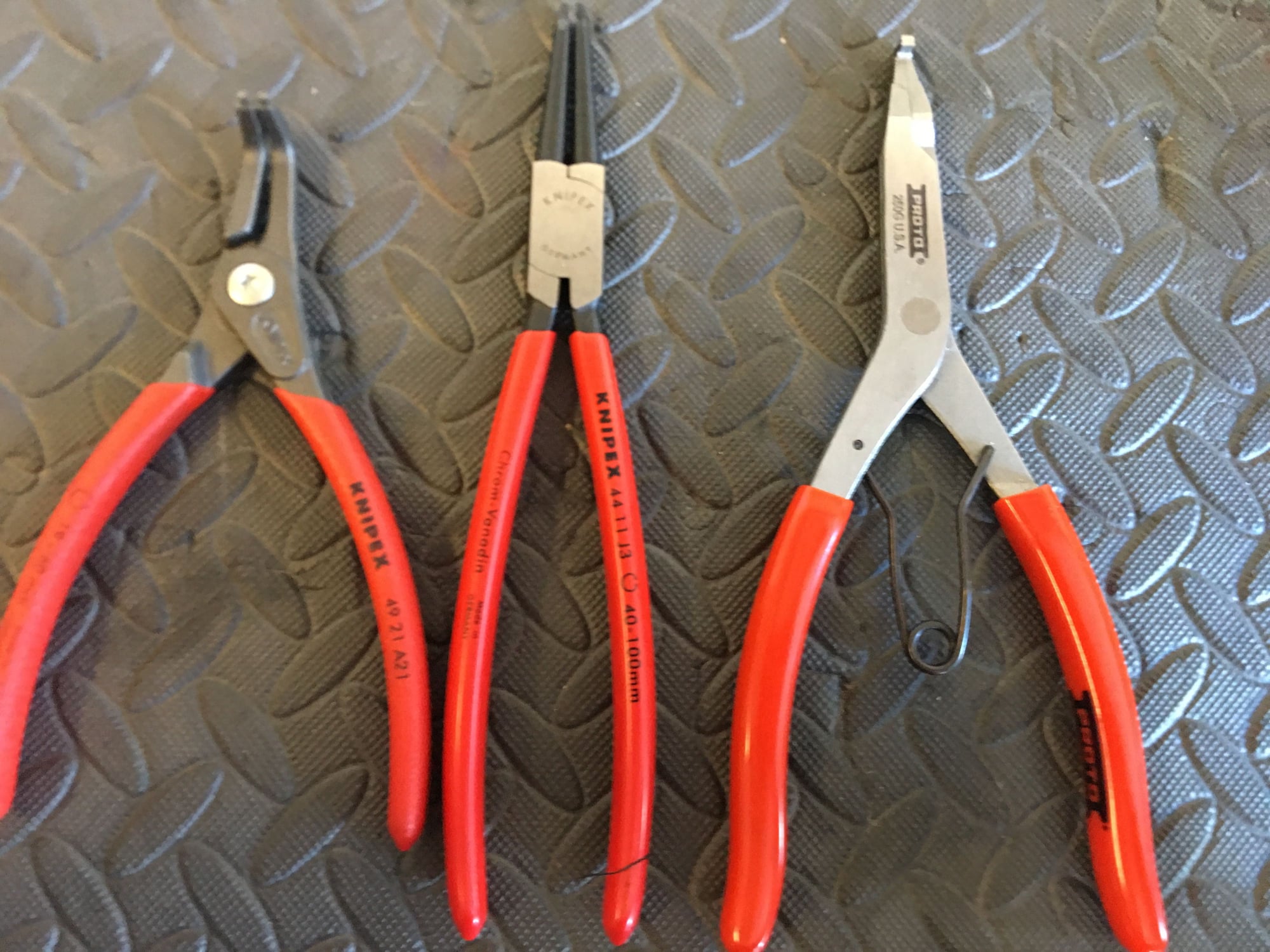
Medium-large “outer” circlip pliers, for removing circlips on the outside of rods. This is needed for, among other things, removing the large circlip at the end of the pinion shaft, the circlip on the input shaft, and (if needed) the layshaft gear. I purchased a Knipex 49-21-A21, for circlips 19-60mm in diameter. This has curved jaws which worked out great.
Large “inner” circlip pliers, primarily for removing the extra large circlip holding in the input shaft housing. This one has to be beefy. I purchased a Knipex 44-11-J3, for circlips 40-100mm in diameter. This has straight jaws which I think worked out great for that application.
Snap ring (lock ring) pliers. These are optional and the only place I think they’re needed is on the rear axles to remove the inner CV joints for cleaning and repacking, if you choose to do that as part of this project. I purchased all three of the above pliers at the same time just for simplicity. I got a Proto 250G. It made removing the snap rings – you guessed it – a snap!! I got all three of these pliers on Amazon.
Press. I purchased a Harbor Freight 20-ton press. It ended up being so useful on so many parts of this and related projects with the rear axles and bearings that I cannot imagine being without it now. I saw somewhere online one anecdote stating that the gears could be removed from the pinion shaft without a press. I will state for the record that this does not sound like a Good Idea - those bearing races are on tight. The press made removal and refitting the gears, and many otherwise difficult projects, a total piece of cake. Well worth the investment! By the way, Harbor Freight does sell a smaller and less expensive press, but I went with the bigger one to be sure that it would physically fit the pinion shaft in between the upper and lower press plates.
Large Bearing Separator. I bought the $29.99 one available at Harbor Freight. I learned right away I really couldn’t get too far on the press without this one vital tool. For tapered bearing race installation and a host of other purposes I was able to use normal items in my garage including sockets, large washers, and the races of old bearings I had lying around (or had removed as part of this project). No special race install tools were needed.
Punch Set. I bought Harbor Freight’s 8-piece punch set for $9.99. This was needed to drive out the split and roll pins in the gear selector rods, plus a number of other miscellaneous uses. I think it was the 3/16” punch that worked perfectly on the pins on the gear selector rods.
And that’s it. I also used, but already had, a metric feeler gauge and a metric depth/dial gauge.
Porsche Special Tools note: There are a number of special tools called for by the WSM. I was prepared to beg, borrow, steal, or recreate any of them if needed but adopted a “wait-and-see” attitude. It would have been nice to have tool 9144 which is a large handle mounted on the pinion shaft bearing housing which would make rotating, yanking out and especially re-installing the pinion shaft easier… but not essential. And the functions of all the other special removal tools and measurement tools can be substituted or replicated with standard tools and a little creativity. That’s true even for the pinion depth and backlash measurements, especially because I primarily needed to ensure I ended up with the same measurements I started with.
Transmission Cradle note: I’m not really counting this as a tool, but I needed a way to safely hold, slide back (/forward), and lower (/raise) the transmission in a controlled fashion. I made a special cradle out of wood that snugly fit the bottom and sides of the transmission, and let it ride on top of a heavy duty wheeled furniture dolly (ten bucks at Harbor Freight again). I also needed a strong tie-down strap, cable or similar for supporting the transmission after the crossmember is removed. I ended up with Harbor Freight “Haul Master” 1-inch by 12-feet lashing straps, package of two (and used both!)
In a later section, I’ll explain how the syncros work and also some of the things I looked for in evaluating wear on the components. But this is a decades-old transmission. Because the goal is to stay out of the transmission for at least the next couple of decades and 100K+ miles, I will be replacing almost all the components I perceive to be “wear components” as a matter of course.
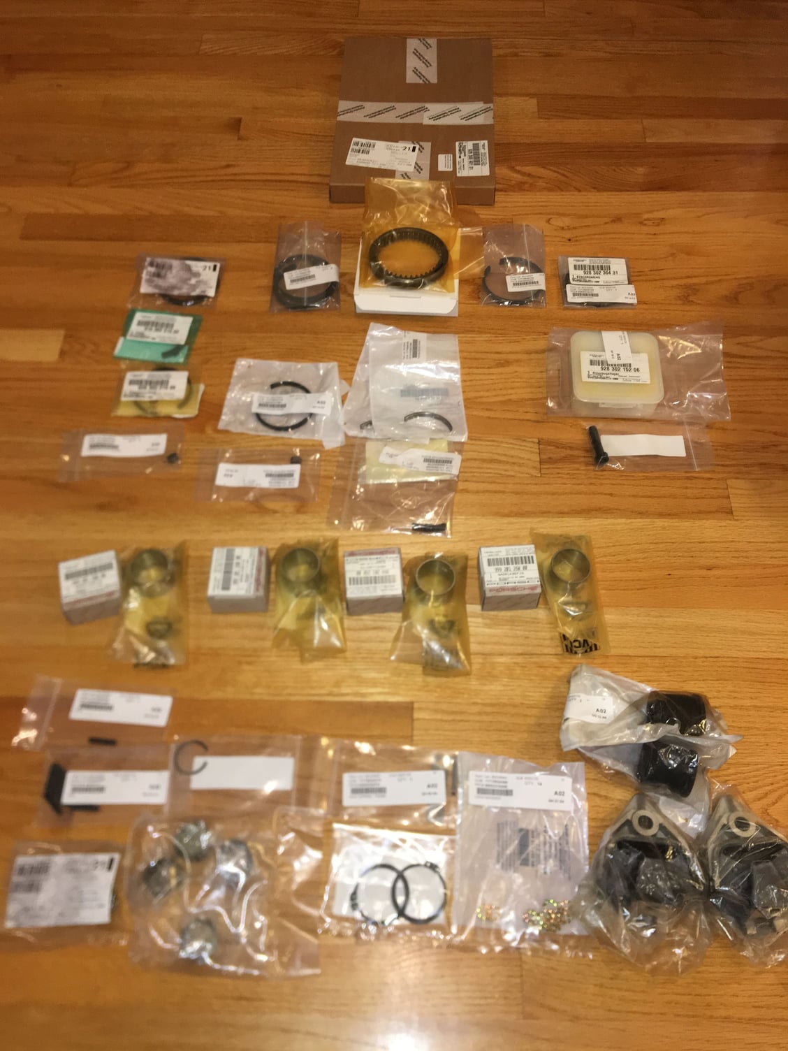
As such, I already have in hand all needle bearings and races for the gears, a new input shaft bearing, all new syncro rings, one new shift ring (spoiler alert: I thought I might be able to re-use the 4/5 ring, but during teardown and evaluation I determined that it had similar wear to 2/3, so ended up replacing both of those rings), all the brake bands/stops/stones (even though these are unlikely to be worn but they’re cheap), a transmission seal kit, new differential carrier bearings, new layshaft and 5th/pinion shaft bearings and a bunch of smaller miscellaneous items including circlips, split and roll pins, transmission mounts, Schnorr washers, input shaft clamping screw, thrust washer, thrust ring, reverse lock and more. I also purchased two new rear swaybar support bushings.
The layshaft needle bearings (2) and the pinion/5th gear needle bearings (2) are the same part (928.302.163.00) and are NLA. However, they are available through Mark Anderson at a reasonable price. I purchased four.
I also priced out and checked availability on many other additional items including the shift finger and shift forks, the pinion shaft bearing, and the various adjustment shims (there are 5 places that require adjustment shims). Almost everything is generally still available. I’ll evaluate these items when I have the transmission apart. I also found a source for what appears to be high quality aftermarket dogteeth, just in case. One of the few other parts that is NLA is the circlip on the end of the pinion shaft, 999.041.036.01.
Little did I know that one unanticipated surprise was still awaiting me…
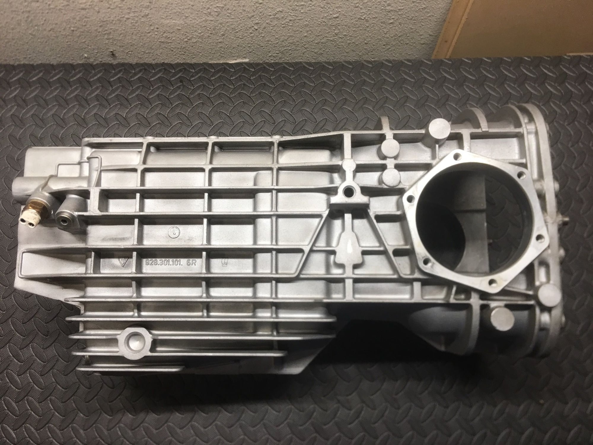
Parts waiting and ready for transmission to be removed
Good! Actually the fun has already ended... successfully back together and working beautifully. I found it to be a straightforward and very enjoyable project! More info and feedback as I go along.
Yes! I think Greg brings up a good point. For some reason, my take on what I�ve read here on Rennlist is that there is some magic or mystery about our manual transmissions and that �vast� experience is a necessary prerequisite to avoid total failure. There�s really nothing very different in the big picture about our 928 transmissions than any other transmissions out there, at least what I saw with mine. The transmission is like anything else on our cars: use some common sense, do the research, figure things out, be methodical and it�s really not that hard. If I can do it, a lot of people can. Having said that, I�m also purposefully putting myself in a position to not have to rely on experience by simply planning to replace most wear items. A few careful measurements to make sure nothing has changed and it�s done. And I�m not doing anything to change pinion depth or backlash, though I confirm both, so that definitely keeps things simpler. But I don�t want to jump too far ahead... let�s focus on some step by steps. More to follow soon.
I've got 'crunchy' synchros in mine. I've been babying it since I got it, and can live with it. But it's not right.
I've been pondering simply pulling it, putting it in a cooler strapped to a pallet and shipping it to Cali. And writing a reasonably big check.
Now this.
Great.
Caveat: I’m no expert, don’t take my word for it but consult and follow the WSM, and I am only sharing my experience and what I’ve learned for informational and entertainment purposes. Removing, working on, and reinstalling the transmission can cause property damage, serious bodily harm or death. And following my (possibly incorrect) procedures could result in a broken transmission, an accident, or worse. I make no representations or warranties of any kind including but not limited to those of safety, correctness, or fitness of purpose. Use any information contained herein strictly at your own risk.
Did you sleep in a Holiday Inn Express last night?
This will be super interesting to see if a "novice person" can successfully rebuild one of these transmissions, using the Internet and the factory workshop manual as an information source.
While I consider these transmissions to be relatively simple, I get sent a tremendous amount of these transmissions that have been recently "rebuilt", but fail to work properly.
I'm going to be, exclusively, a "watcher" here, just so my vast experience with these transmissions won't affect the outcome.
Let the fun begin! (Although from reading the first few posts, it sounds like this job has already been done and we will be getting a recap.)
Originally Posted by GregBBRD
...As you get to those particular areas, If you don't mind, I'll show what I've got, for that application.
I really have to laugh about this. Let me get this straight... you're like an uninvited guest who shows up at a pool party showing off a lifesaving ring... and sit on it while declaring that you will refuse to help any poor hapless drowning victim! And meanwhile, you thump your chest on what a great lifeguard you are!! Then when it turns out that nobody drowned, you now want to join the party?
If you can't follow the kindergarten rules ("constructive" comments are welcome, trolling and baiting such as the above are not)... then yeah... I'll take you up on your promise to stay out.
I'm hoping that this turns into good DIY/How-To thread on the gearbox, narrated by a non-expert so that non-experts can follow along. Hints and suggestions to the process, presentation and style are certainly welcome contributions, and can be included in the edited final product. Try to keep this all in mind as the thread proceeds.
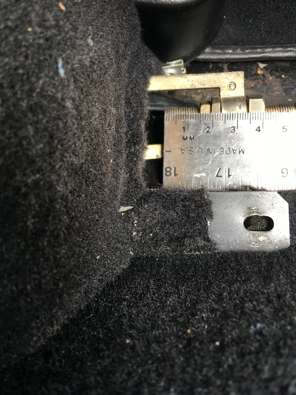
After disconnecting the battery, I removed the cover behind the parking brake handle, measured the current setting of the adjustment, then unthreaded the parking cable from the handle. I�ll save that measurement and (hopefully) just replicate it when everything goes back together:
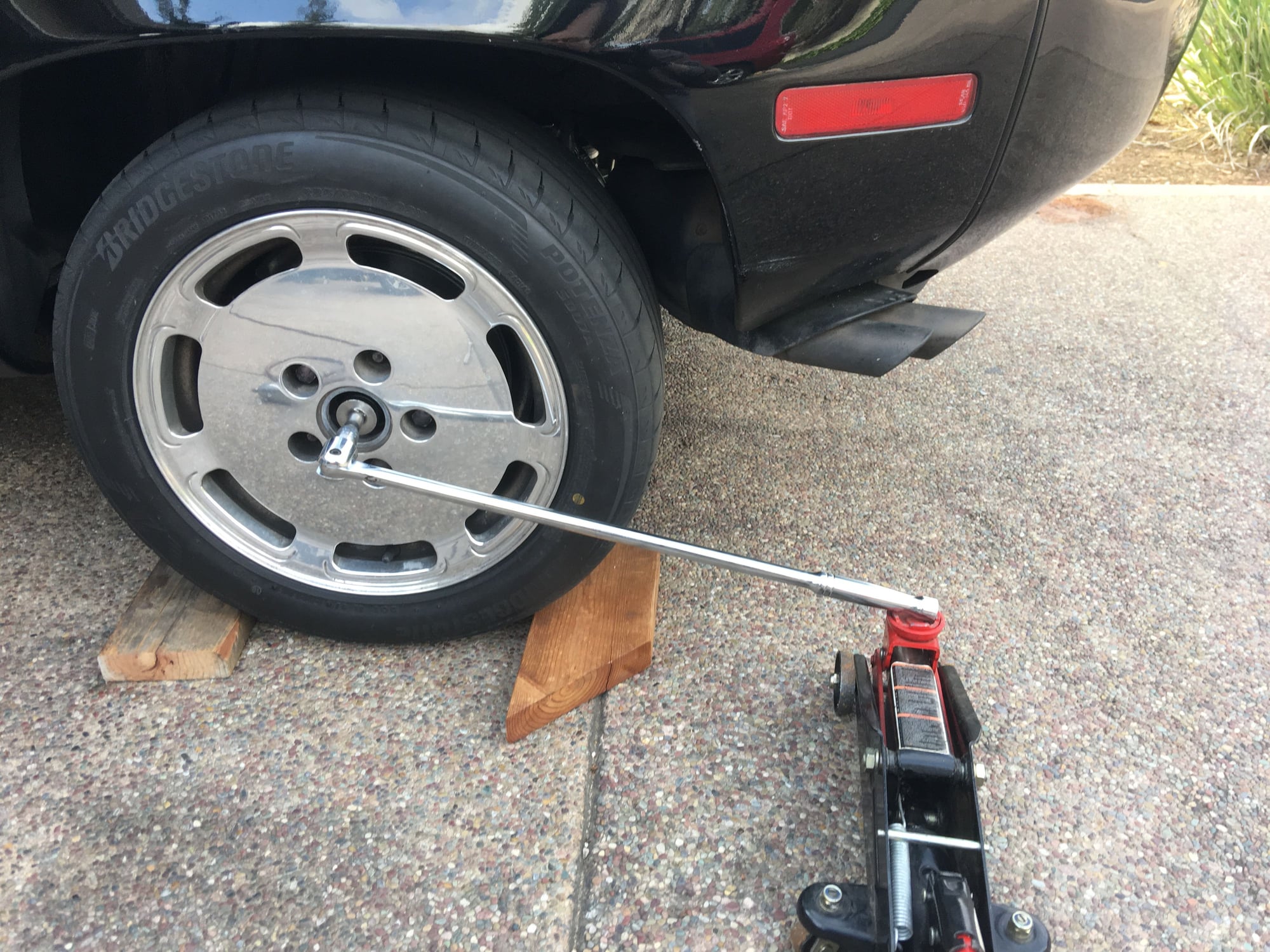
I knew that I�d be doing an axle R&R as part of this project, so before diving into the crossmember removal I knew it would behoove me to loosen the two gargantuan axle nuts. I remove the rear wheel center caps, and then with wheels on the ground and chocked I used the largest breaker bar I had, set in the end of a jack. I raised the jack lifting the end of the breaker bar to break loose both nuts, then removed the nuts. I�ll be replacing the nuts and the washers later.
I then drove the front of the car on top of 4� wood blocks and jacked up the car in the rear about as high as I could get it from the center of the crossmember and placed jackstands under both rear jack pads. Each rear wheel was off the ground perhaps three inches � this turned out to be just enough space to get the transmission out on its cradle and dolly later.
I removed the exhaust system from the back end of the catalyst � it�s a big single piece with the intermediate muffler, rear muffler, and tips. It�s held in place by three mounts, and four bolts at the back of the cat. I supported the rear end of the catalyst so it wouldn�t put too much stress on the headers or cats themselves. I photographed each mount and its adjusted position prior to loosening so that I could re-hang the exhaust system in the same position later. This really only applied to the two rear mounts, as I didn�t need to loosen the center/forward mount (hanging from the torque tube) and only needed to slip off the rubber hanger.
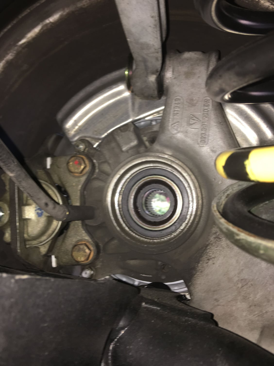
I used this opportunity to remove the twelve cap bolts (six each side) that bolt the inner CV joints to the transmission output flanges. Having the wheels still on made it easy to rotate the wheel slightly to access each bolt in turn, and also chock each wheel to get adequate leverage to loosen each bolt. I then completely removed the axles. The WSM calls for simply unbolting the inner CV joints, which is fine if you�re not going to be doing any rear axle or rear bearing work.
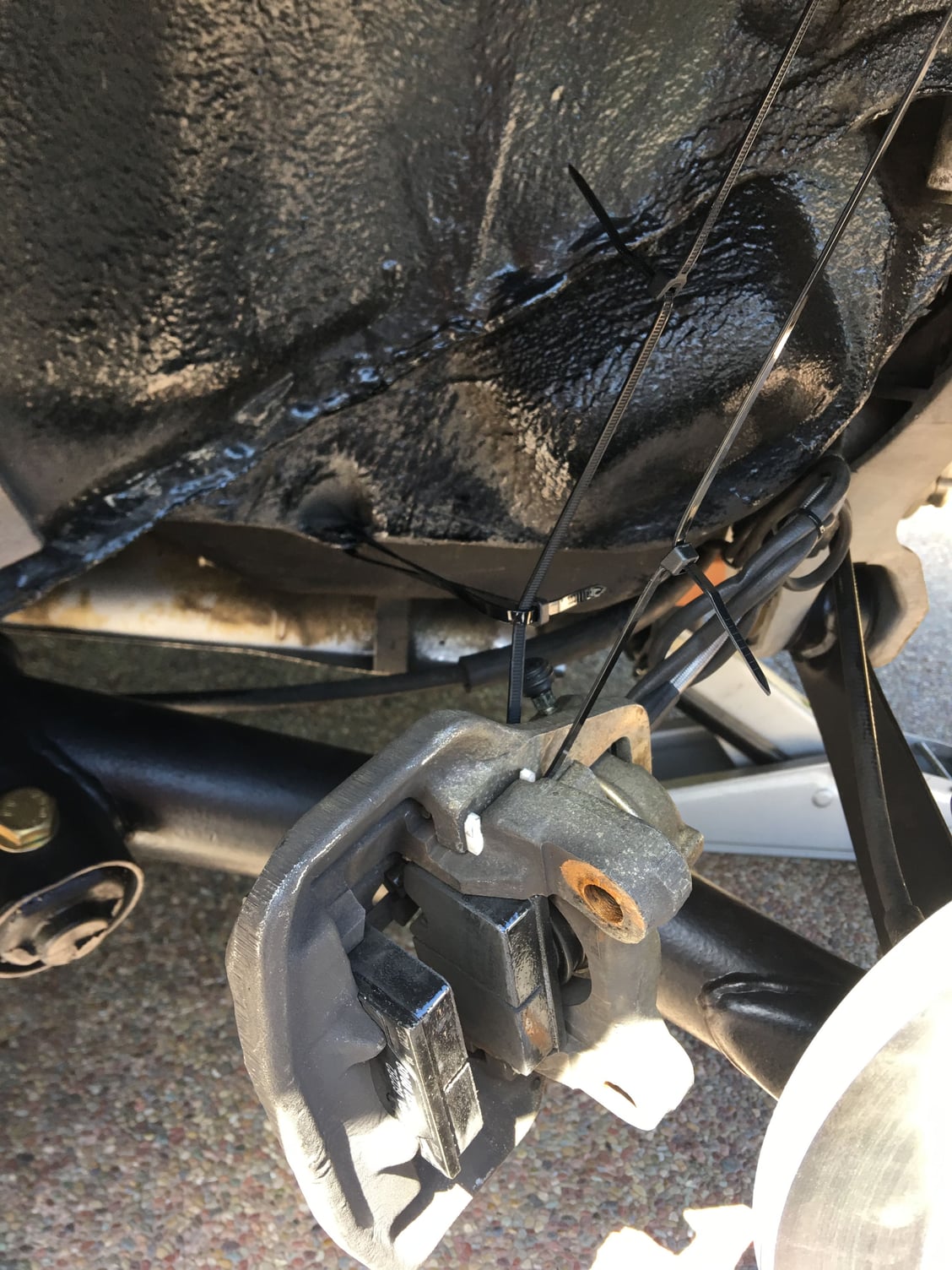
After then removing the wheels, I removed the rear calipers (two bolts each) and hung the calipers, still connected to their fluid lines and pad sensors, with some extra long zip-ties hanging from convenient locations above. I also removed both rear rotors.
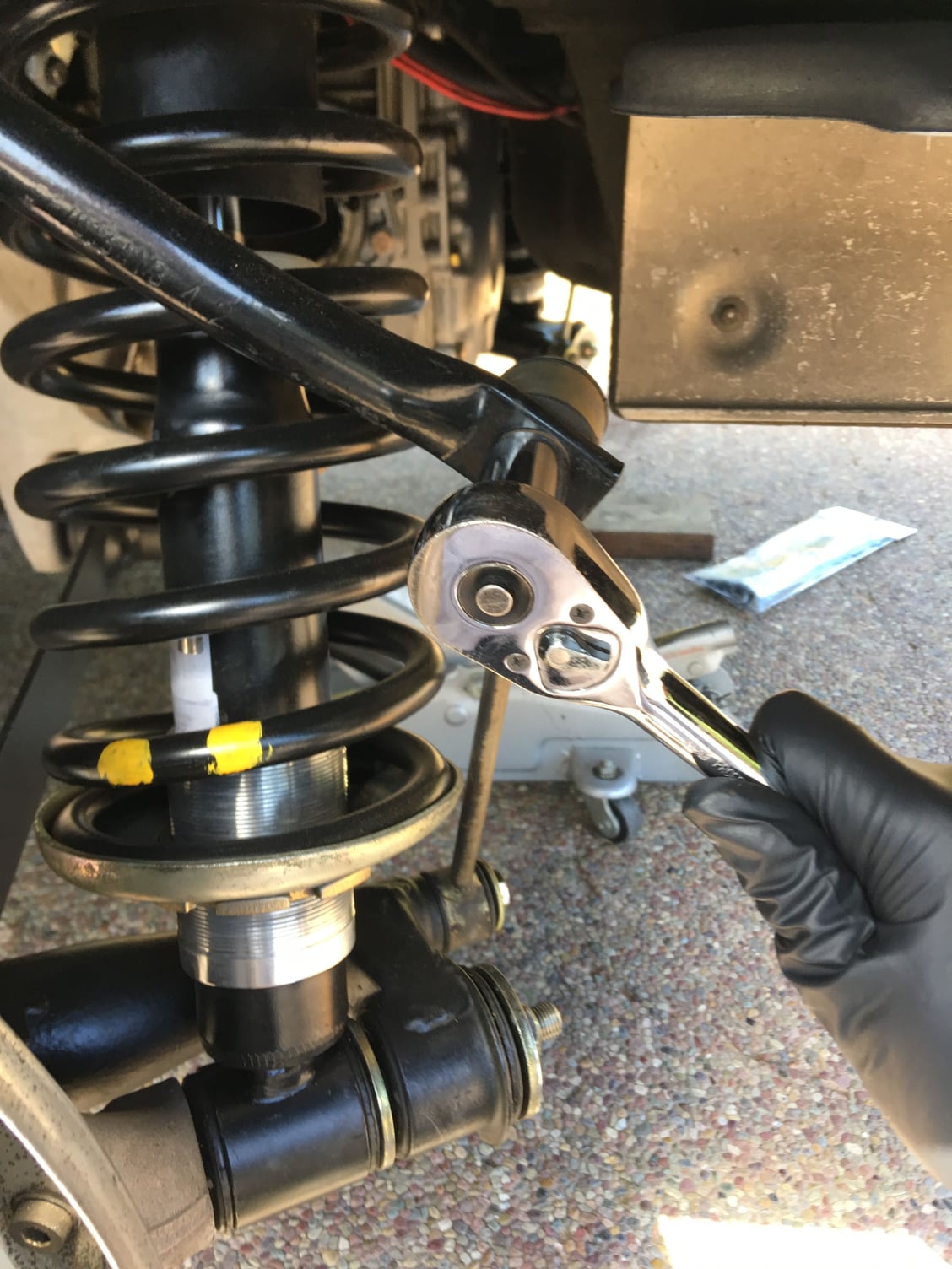
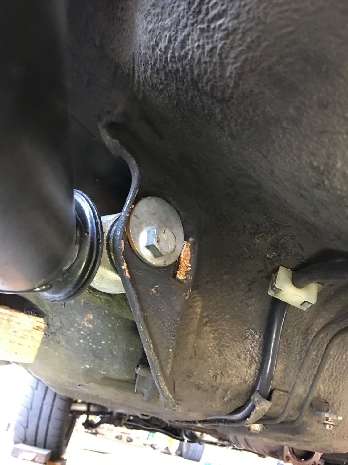
Next, I removed the bolts at the upper end of the sway bar links, and loosened the bolt at the lower end of the links (that bolts into the lower suspension arm). That lower bolt can be left loosened but in place.
I marked the current location of the crossmember onto the body with pencil. I also took a bunch of photos of both sides so that I would be sure I placed the crossmember back in exactly the same position.
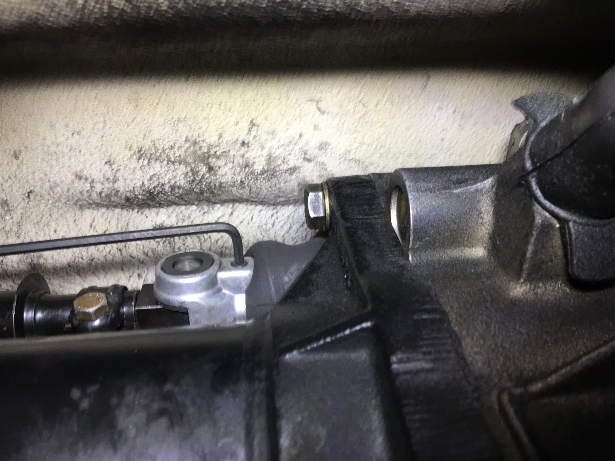
I removed the heat shield near the transmission, pushed back the rubber boot holding the shift coupler, and loosened its set screw. I put the transmission in 5th gear to get clearance to push back the boot and to be able to turn the input shaft (next step):
The next step is to remove the input shaft clamp bolt. I needed to rotate the driveshaft to get access to the bolt. I debated just turning over the engine with a big wrench from the front of the crank, but instead I used one of the output flange cap bolts threaded through the flange and into a recess of the transmission case to lock that side. I had my son sit in the car and press the clutch in while I rotated the other output flange. Because the transmission was still in gear, this rotated the driveshaft, until I could access the clamp bolt. I completely removed the bolt or the shaft won�t come free. I also followed the advice from another thread and left the clamp (sans bolt) on the input shaft to help prevent any of its tangs from breaking off during disassembly. I did the same thing in reassembly:
Next, I took one of the two Harbor Freight tie-down straps, draped it from the rear swaybar on one side, across the bottom, up and around the bar on the other side, and back again. I tightened this snug. This strap will support the entire weight of the transmission when the crossmember is removed. As you can see, I also took this time to go up in the battery area, unplug the harness from the transmission, and feed the harness and its seal out of the interior. The WSM has you leave the harness in the car and disconnect it from the transmission, but I felt it easier to leave it on the transmission and disconnect it from the car:
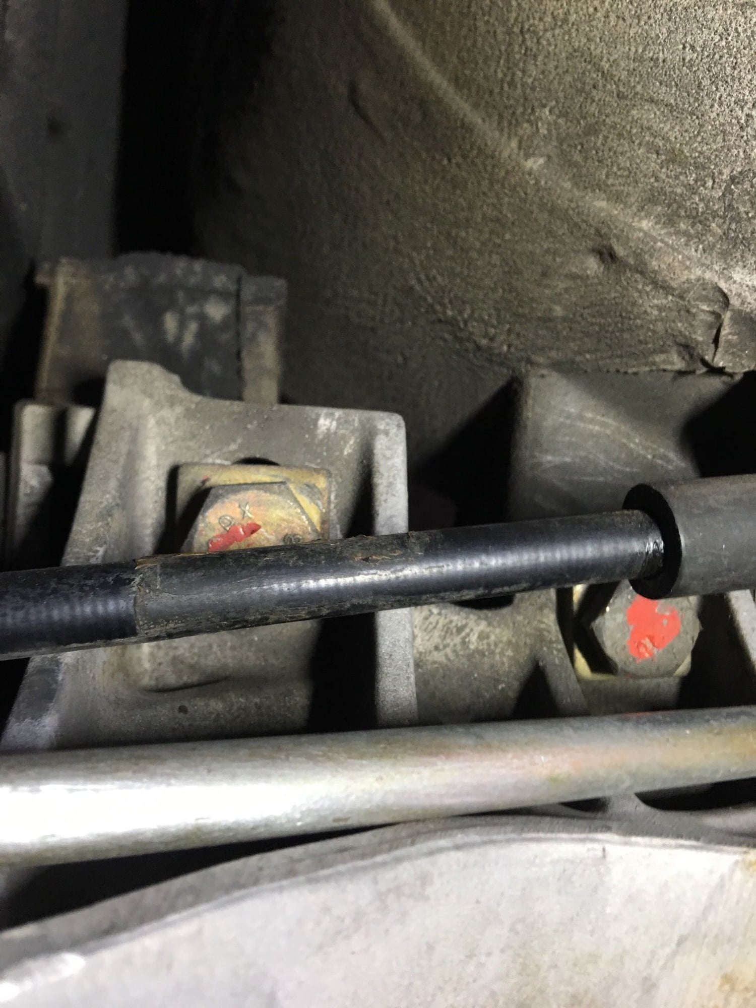
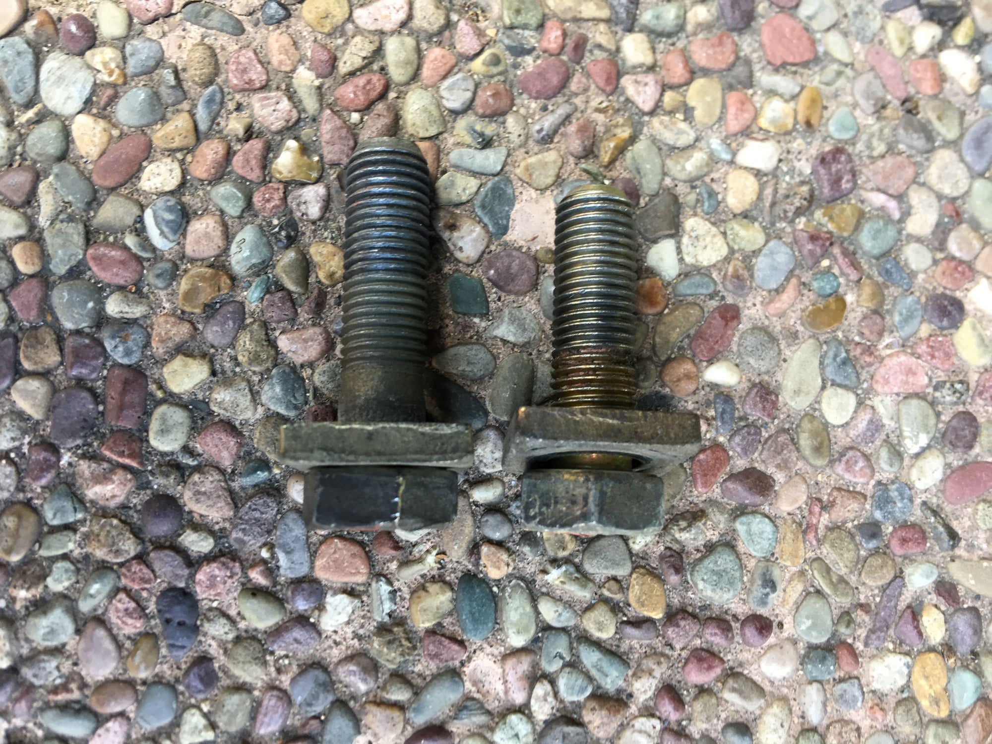
I next removed the four large bolts in the middle of the crossmember (two mount the transmission to the crossmember, and two mount the crossmember to the body). Take note of which bolt is which as they are different:
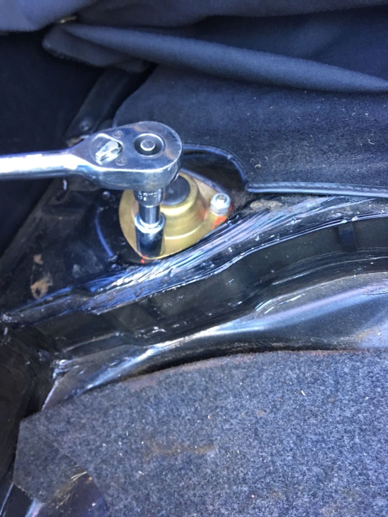
I loosened and removed the six nuts mounting the upper spring supports to the body:
At this point, only four bolts are holding the crossmember itself still in place, two at each outer edge. Before loosening them, I placed a support jack, on a wood cushion of course, to support the crossmember:
I removed the four outer crossmember bolts, then � without letting it swing down just yet � loosened the two track alignment bolts at the leading edges of the control arms. Also, at some point along the way, removed the parking brake cable housing from the body. I also loosened, but did not remove, the link pin nuts.
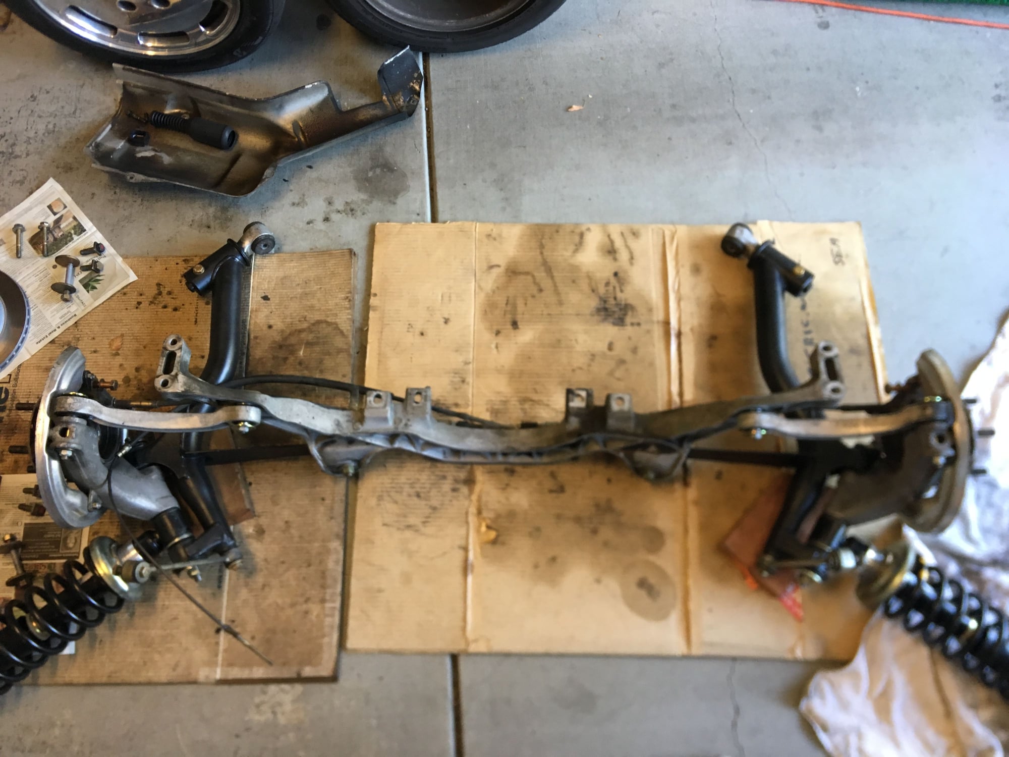
I now gently lowered the crossmember via the jack, making sure the upper spring perches came out evenly, all while keeping an eagle eye on the transmission to make sure the tie-down strap was doing its job. The transmission did not appear to budge at all as I lowered the crossmember. After I got the perches� studs clear of their mounting holes, I removed each track alignment bolt in turn and persuaded the bushing to release from the body. I had put in new shocks and suspension bushings recently, so getting the perches and bushings to slide out from their mounts was actually pretty smooth. As the crossmember got low enough, I swung the springs out to waiting towels on the ground to avoid any damage. My son and I were then able to slide the whole thing straight out (we went out to one side!) and into the garage where it shall await further �enhancements�:
By the way, word to the wise: You can see in the above picture if you look carefully that I've propped up the back of each suspension arm with a block of wood underneath the big link pins. If you don't do this, the weight of each hub will likely sit on the bottom edge of the thin aluminum brake rotor shield (which could get bent). I somehow anticipated this and had some sections of 2x6 ready. I�m also protecting the springs and spring seats so they don�t get scratched.
Thanks for posting this. I know it is much more work to document the process than to just do it. I probably have this task in my future, since I am thousands of miles from Greg.
Thanks Karl! It's certainly not hard to ship. I think people have talked about styrofoam coolers. But on the other hand, you're right, it was practically more work to document the whole thing than to do it. It's also been one of the most rewarding projects I have ever done on the car. You'll feel it every time you shift!
I had found a note somewhere on Rennlist to be mindful about how the entire engine and torque tube assembly can tilt as part of removing the transmission. If the back of the torque tube is allowed to move downward, the engine will tilt with it as it�s only balancing on two motor mounts, potentially pushing the air cleaner box against the firewall and causing damage. Although my goal is to avoid any tilting at all by supporting the rear of the torque tube at all times, I decided to remove the air filter box before proceeding as a precautionary measure.
The WSM has you use a special external transmission removal mount that bolts to and supports the transmission and is supported in turn by a special standing jack. I don�t have any of that, and also my car isn�t on a lift so it wouldn�t work anyway.
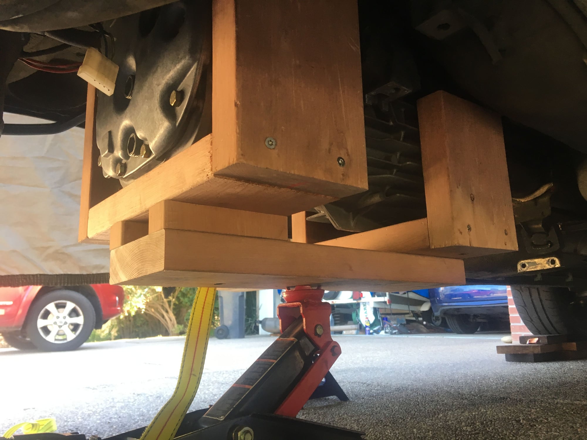
Instead, as I constructed a big backyard redwood deck last year, I had some redwood 2x6 scraps lying around plus my 12� miter saw, deck screws, and some corner reinforcement plates. After a few measurements I constructed a cradle that supported the bottom and sides of the transmission. Note that the bottom of the transmission isn�t all on one plane, so there is a step built into the cradle so that its �keel� remains horizontal when holding the transmission horizontally. I also debated whether I should build in some angle to reflect whatever small angle the car was jacked up to, but decided that the car was actually almost horizontal and that any minor geometric irregularities would take care of themselves. (The key here is that the transmission should slide back along the axis of the torque tube and drive shaft for smooth decoupling � and to avoid damaging the 3-pronged input shaft/5th gear on the transmission). Also, I wanted to make very sure that the transmission didn�t roll over to one side during the removal or reinstall, so I built two pairs of vertical supports � one that fits snugly around the output flanges at the back and one that fits snugly around the transmission case itself at the front.
After gently installing the cradle around the transmission by raising it into position with a jack, I debated whether the jack alone, or perhaps two jacks, would be adequate. That didn�t seem stable to me. Instead, I purchased an inexpensive Harbor Freight large furniture dolly. I figured that using the dolly would be perfect to allow me to wheel the transmission back from the drive shaft in a straight line.
I slid the dolly under the cradle and used more 2x6 and other scraps to firmly support the cradle with the dolly.
Here I�m raising the cradle into position:
And here is the cradle on the dolly, ready for �release�:
At this point, after having worried about what I perceived as perhaps one of the most difficult challenges of the entire process, actually removing the transmission was almost a non-event.
After ensuring the dolly and cradle were firmly supporting the transmission, I first removed the tie-down strap holding the transmission to the swaybar. (For simplicity, I actually just cut it off!) The transmission didn�t perceptibly move down, which is good. I then supported the back of the torque tube so that after removing the transmission it wouldn�t swing down. (If you are paranoid like I am, you�ll probably want to support the UPPER side as well to prevent any possible movement in that direction too). I then removed the six bolts holding the transmission to the torque tube, and ever so gently slid back the transmission from the back of the tube:
(That�s actually a picture from when I re-installed the transmission!)
At this point, the transmission was free of the driveshaft. I slid the dolly back as far as it would go, then used a jack to gently raise the transmission fore or aft to remove the extra supporting wood blocks and lower the transmission and its cradle until the cradle was resting directly on the dolly. At this point I could turn the transmission and wheel it out to the side. It came out much more easily than I had imagined. However, it sure is a lot DIRTIER than it looked like from the bottom!!!
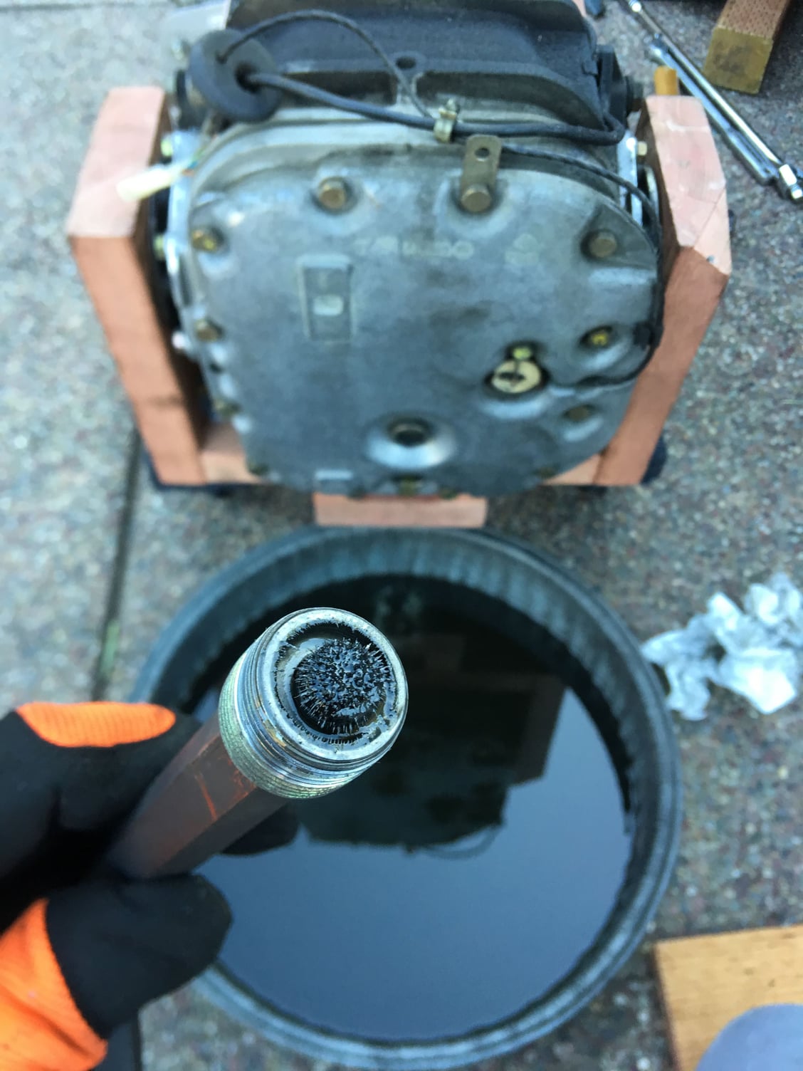
At this point I drained the oil from the front and rear drain plugs. I felt it would be easier to drain after removal than with the transmission in the car. My next order of business was to clean off the case as much as possible before going any further.
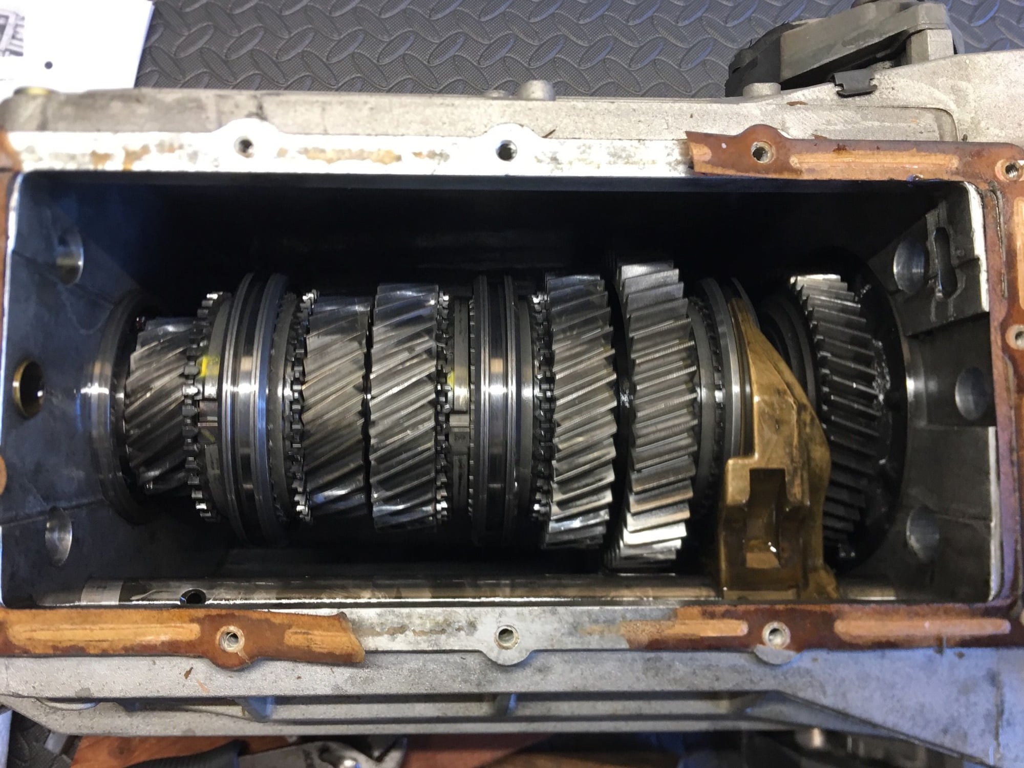
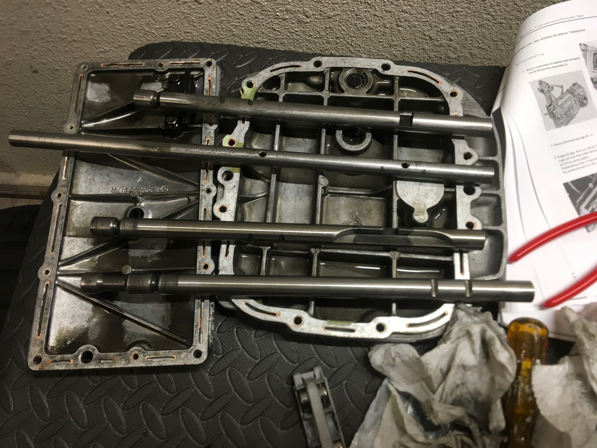
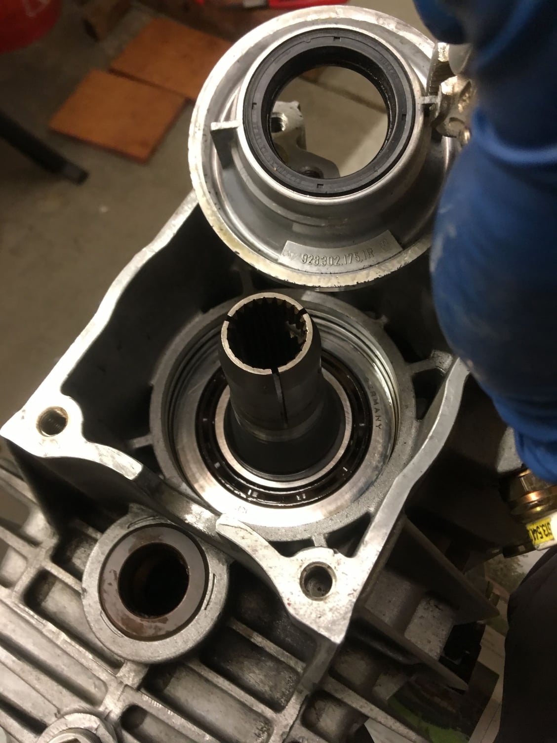
After removing the top and rear covers, but before disassembling anything, I wanted to measure the existing backlash and pinion depth. Here’s what it looks like when the rear cover is removed:
It’s a little dirty in there. Note to self – replace transmission oil religiously on schedule next time!
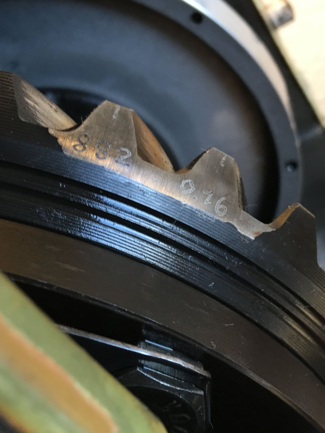
The backlash unique to the pinion/ring combination installed in the transmission is inscribed on the ring gear:
The specified backlash is what was determined by the factory when the parts were brand new. Some threads I have run across state that the expected backlash for normal wear should be about 20-25% greater than the factory backlash. In my case, the factory backlash is .16 mm, which means that – hopefully – I will find a backlash measurement somewhere in the range of approximately .19-21 mm.
As an initial note, chapter 39 of the WSM has a wonderful writeup on everything you need to know about how to measure and adjust pinion depth and backlash. Page 39-14 also has a table to describe what should be adjusted depending on what parts are changed.
I knew that I would be changing the differential carrier bearings, but I wasn’t sure whether I would need to change the pinion shaft bearing. I’ll have to wait to inspect that later. Some of the 915 threads I studied opined that changing only the differential carrier bearings would rarely, if ever, be reason to adjust the side cover shims. These threads – as well as other information I saw online about differentials generally – indicate that the shims are really about the differential and case, and not about the bearings. In other words, once the shims are set at the factory, there should rarely be a need to re-shim with the same case and differential combination. So… let’s “trust but verify.”
Backlash
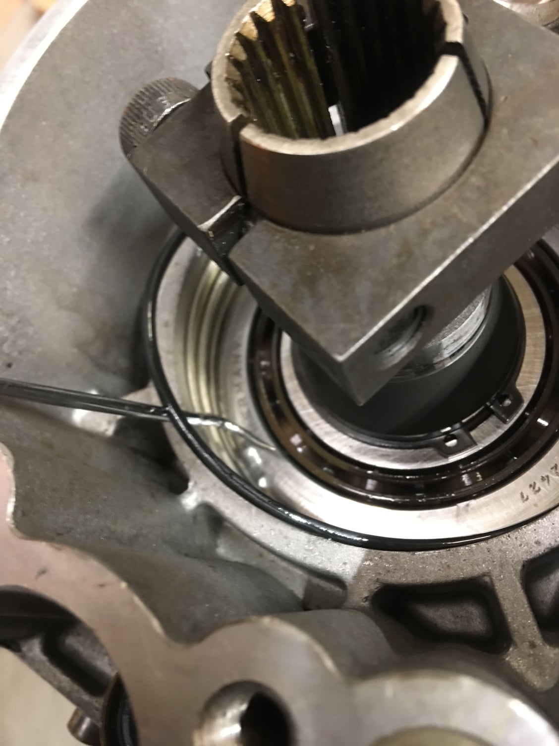
Because I didn’t have the special measuring tools shown in the WSM, I decided instead to measure the backlash by jury-rigging a clamp to hold my dial gauge directly against a downward-facing edge of a ring gear tooth at the back edge of the transmission. I reasoned that although this may not be precisely the prescribed radius of 80mm (which I think corresponds to the middle of the gear, not the outside edge where I’m measuring) and there may also be some minor geometrical artifacts with measuring against the ring gear tooth, it ultimately didn’t matter. All that does matter is that, when I put it back together, that when I measure in exactly the same way, I need to end up with exactly the same backlash measurement. There are also going to be variabilities based on how much oil is on the gear, as well, but for my purposes I’ll not wash off the gears between now and reassembly.
There’s still a bit of rotation of the pinion shaft possible even with the gearset locked as described in the WSM, so you can make the simple locking tool described in the WSM, or I simply used a big blunt screwdriver with a towel around it placed against a gear and braced against the side of the case which performs exactly the same function but at the expense of requiring an extra hand. With a little “touch” on rocking the gear with just the right force, I found I could get very reproducible measurements.
I measured at four different places across the ring gear (ninety degrees apart) and my measurements were all at or within measurement noise of .20 mm. I will re-measure the same way when I’m all done to make sure it is the same.
Pinion depth
Finally, for pinion depth measurement, the WSM has you remove the diff and use a special tool which measures from the rotational center of the differential to the top of the pinion. The tool basically fits into where the diff bearings would normally go on the left and right sides of the case, and centers itself along the same axis as the diff. You need to remove the differential to make this measurement. Without the special tools, it’s going to be pretty hard to find and measure from the rotational center. But to merely ensure that I correctly replicate the current pinion depth that’s there now – which is all I need to do – it is a MUCH easier measurement from the back of the case to the top of the pinion gear. (In fact, even if you had to re-shim the pinion and set pinion depth from scratch, I think it would be possible to do a few measurements from the back of the case and some math to come up with the distance “R” shown in the WSM, but I didn’t need to go there). I removed the remnants of the paper gasket on the rear face of the transmission, placed a flat bar of metal across the back, and used a depth gauge to measure from the case surface to the top of the pinion. I will save the measurement for later and measure in just the same way (and from the same location across the back) after reassembly.
I placed each side cover, with its associated shims, in a separate and labeled plastic bag to ensure that I didn’t mix the sides or the shims up. I also marked the top edge of each side cover so that I can re-install each in exactly the same orientation later. I’m going to assume that it matters. I also placed the differential/ring gear assembly itself in a large plastic bag to keep it clean until needed again.
I don’t really have a lot to add here to the WSM disassembly procedure, so I’ll let the pictures do most of the talking.
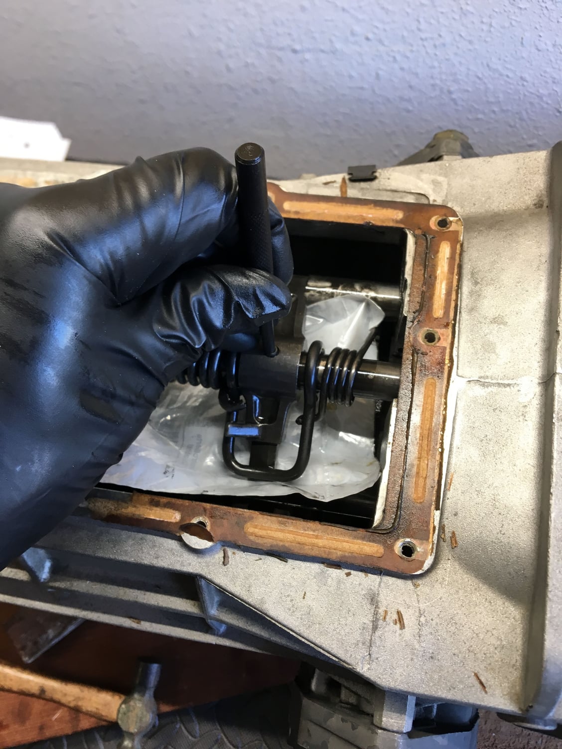
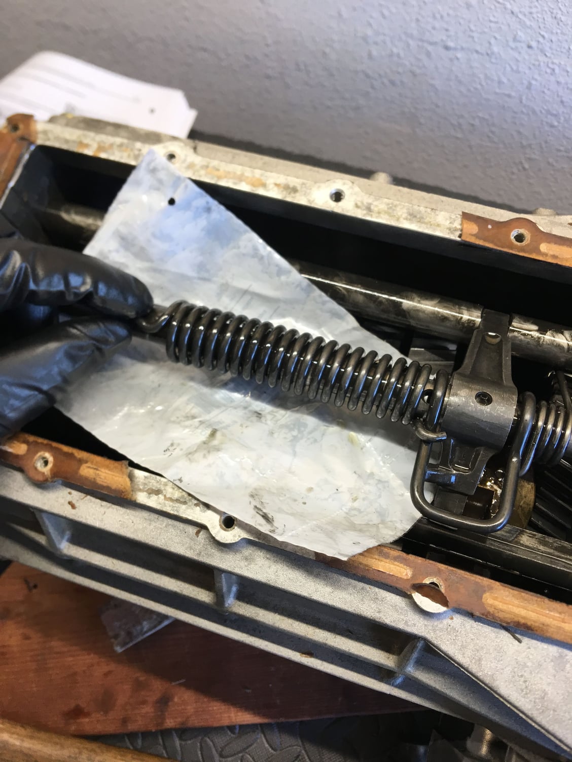
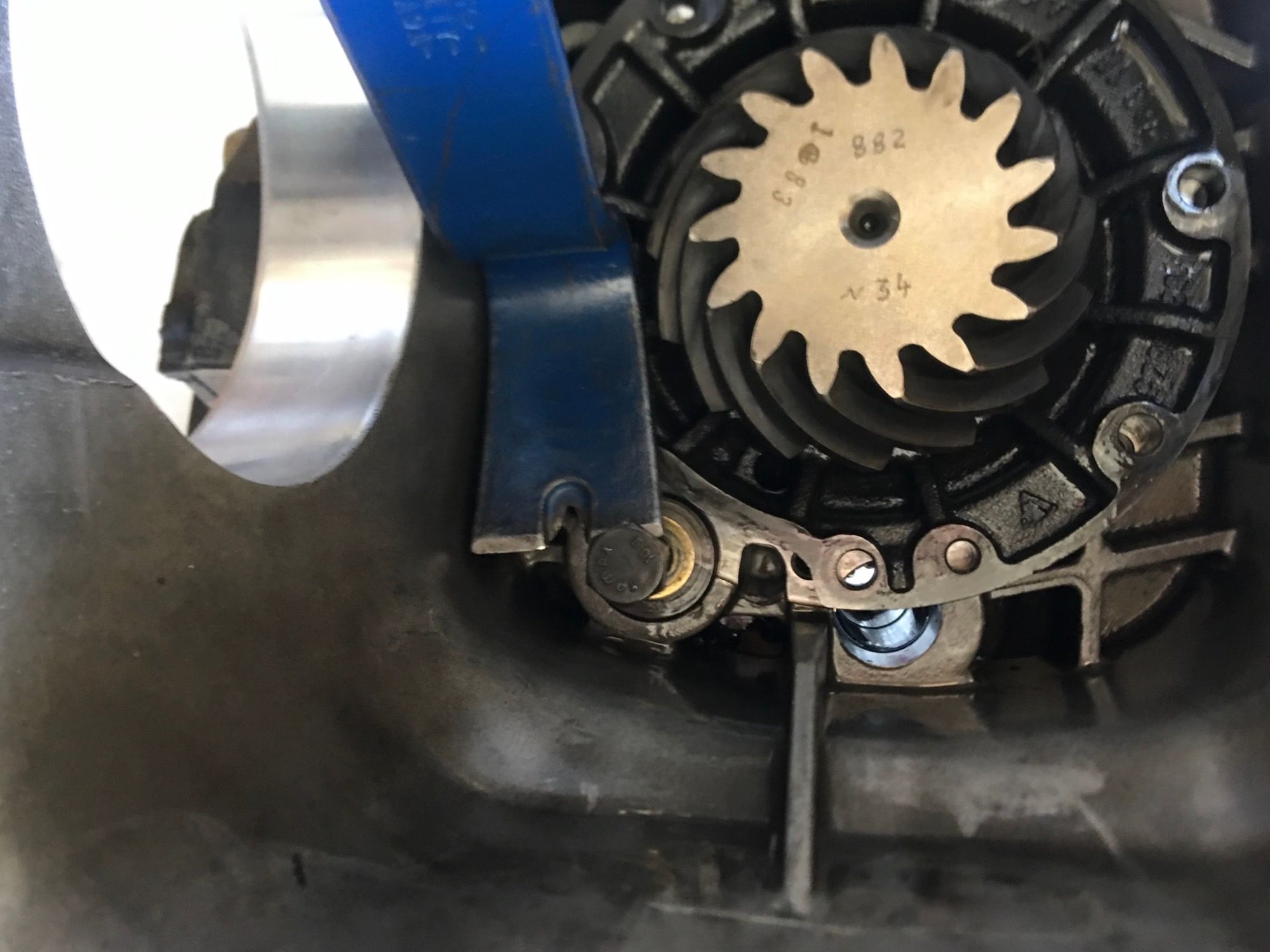
I took a look at the non-functioning reverse gear lockout when I opened the top cover. It’s attached to the top cover. The lockout was still on one piece, and to my surprise the spring wasn’t broken. But the little moving piece was very loose and didn’t seem to be in the correct position. I think the little pin/bolt that holds it in place is worn out – the moving piece is too wobbly and won’t stay in correct position against the spring. This will be replaced, and the spring too.
The first order of business is to drive out the roll pin on the shift finger on the selector input shaft. The spring is under rotational tension and the WSM warns that this pin must be removed first. As an aside, PET specifies this as a split pin, while the WSM refers to it as a roll pin (=stronger than a split pin). The shift finger absorbs all the force of the gearshift lever with every shift, and must not only translate (like the forks) but must also rotate (unlike the forks). It makes sense that this should be a roll pin. PET seems to have it backwards by showing a split pin on the finger and a roll pin on the end of the spring. During reassembly, I adopted a belt-and-suspenders approach here by placing new roll pins in BOTH positions on the selector input shaft.
I also replaced all the split pins on the shifter forks with new pins as well, as a matter of course.
Note that I’ve put plastic underneath the pins to catch them as I drive them out. Probably not really necessary but I didn’t want to find out the hard way what could happen to a pin rolling around the bottom of the case. Now the pin at the end of the spring can be removed:
Now the gear selector rod can be slid out the front of the box:
I then removed the pins on the 4-5 and then 2-3 gear selector forks, again catching the pins each time. The trick now is to slide out the selector rods to the rear while leaving the forks in place (the forks wrap around the shift rings and can’t be removed until the rods are out). The rods don’t want to slide out too easily. I used a punch held vertically, butted up behind the end of a shift rod, or if possible inserted loosely into one of the holes in the rod for a split pin, with a few taps of a small hammer (towards the back of the transmission) on the punch to give the rods some encouragement as needed. Taps are the key word here. The 4-5 and 2-3 rods were reasonably easy to drive out the back side of the transmission this way.
Here’s what it looks like with just the 1-R rod/fork left:
At this point I discovered that the 1-R gear fork was especially tight on its selector rod. I eventually tapped it off, but I should have simply heated the fork and it would have slid right off. Note to self on reassembly: Heat the 1-R fork! That might not be a bad idea with ALL the forks for both disassembly and reassembly.
Here’s where I was at now:
Next up was to remove the circlip for the countershaft and remove the countershaft. I did this with the transmission standing straight up, to hopefully prevent having the layshaft gear suffer a sudden fall to the bottom of the case:
I slowly returned the case to level and could see that the layshaft gear did indeed move down about a centimeter or so.
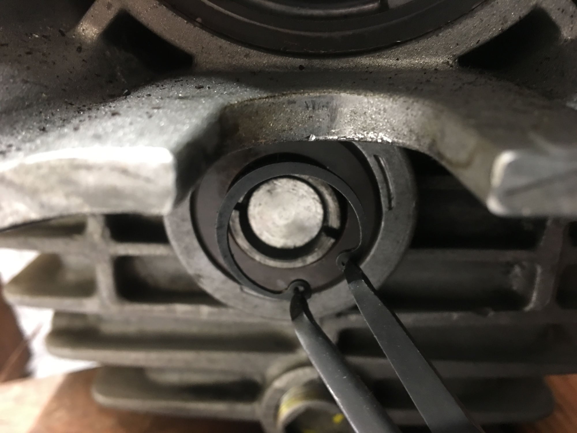
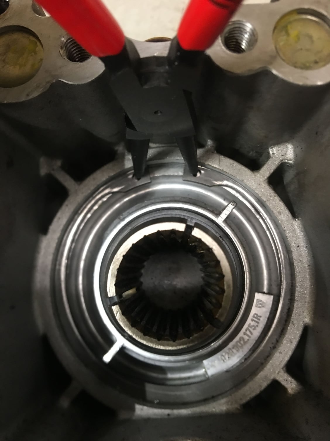
I next removed the giant circlip for the input shaft using the large circlip pliers:
The WSM calls for the input shaft cover to be removed “by turning and pulling.” I grabbed onto its “fins” with pliers on both sides and ever so gently rocked it up and down. I could feel the cover pop loose in its socket, then it “walked” it out. It came out very smoothly. The picture shows vice-grips on one side but I used some pliers on the other side too. As a precautionary note, I’ve read here on Rennlist where people have broken off these fins, so I was sure to be gentle:
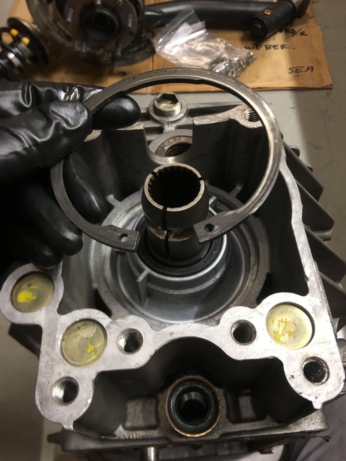
Remove the O-ring:
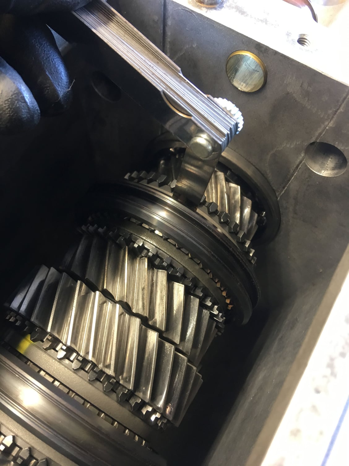
At this point, all the shift selector rods are out and you can get a good idea of the condition of the various dog teeth and have an initial look at the syncro rings, though you can’t really tell too much from the syncro rings at this point (though the yellow paint stripe on each ring can give you some indication of wear).
Before pulling out the input shaft, it’s a good idea to check measurement “Z” as described on page 35-15 of the manual, the distance between the 4/5 guide sleeve at the end of the pinion shaft and 5th gear syncro/end of the input shaft. On the G28.08 transmissions this should be .4 to .6 mm. Mine was .5 mm. This distance would only change if you change the position of the pinion shaft (e.g. new pinion bearing or different shims on either side of the bearing housing). Even though I’m not planning to change any of those, I wanted to make sure that the measurement is the same (and correct) when I put it back together again. (BTW judging by the lack of oil I think I took this on assembly, not teardown)
Next, the WSM has us use a special tool to pull out the input shaft (and 5th gear) and the associated big input shaft bearing with a special puller tool. I didn’t have the tool, so instead I placed the clamp ring back on the input shaft, threaded the clamp bolt back in, and used two small prybars (GENTLY leveraged against blocks of wood on the front of the transmission) to walk the input shaft out. Like the input shaft cover, the input shaft bearing came loose pretty easily and the trick is to “walk” it gently out. I got the bearing partially out… BUT THEN… it stuck!!
At first I thought that I must have wedged in the bearing while walking it out and perhaps gotten it cocked at an angle. But then I realized that 5th gear was hung up on the layshaft gear. I later realized that the layshaft gear has to “fall down” in just exactly precisely the right spot, or 5th gear won’t clear the layshaft gear. Space is really tight in there.
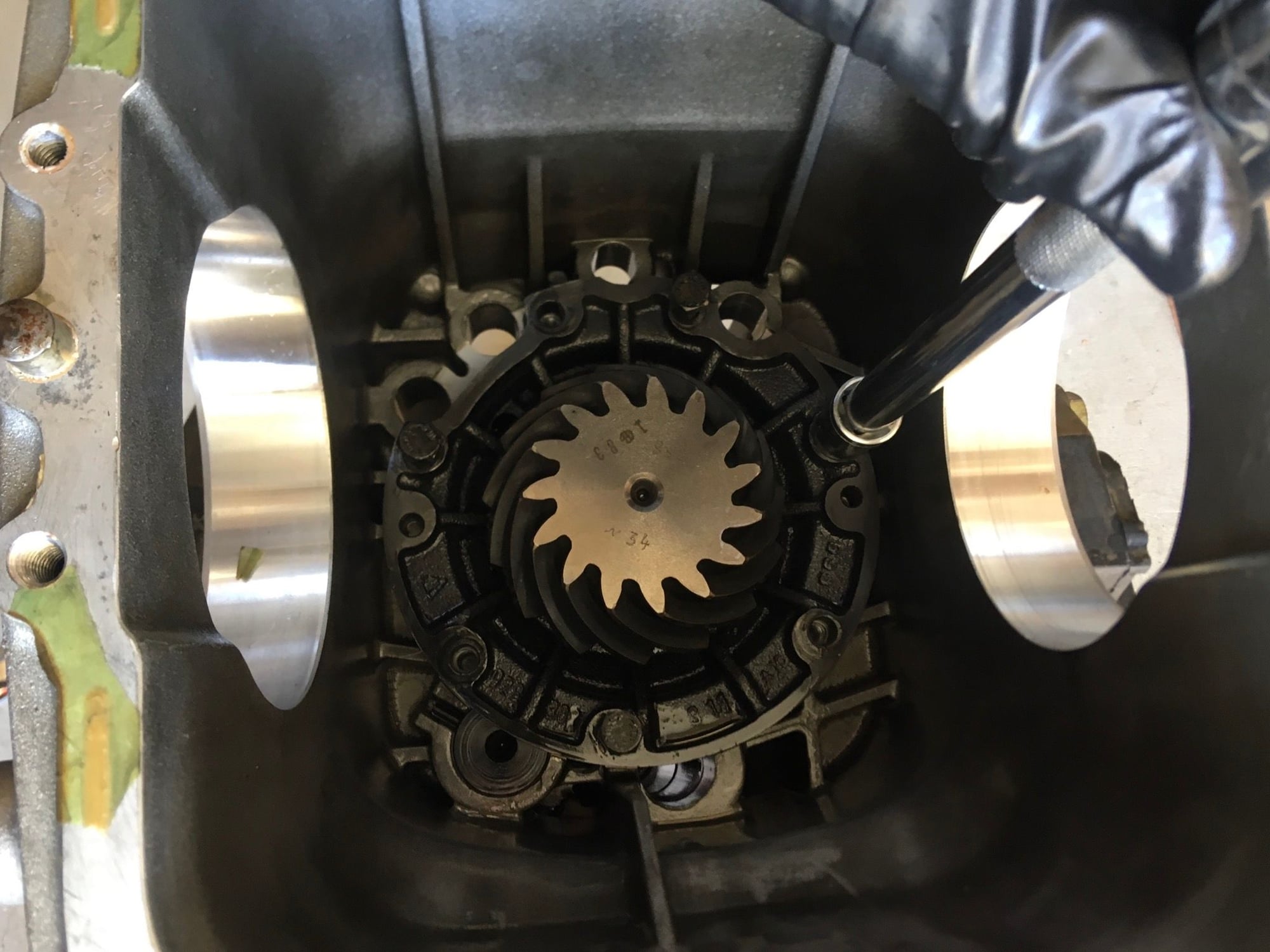
Rather than fight it, I realized that I could do an end-run on it altogether by simply pulling out the whole pinion shaft/gearset, and remove the input shaft and the layshaft gear afterwards. So I did that instead. I removed the pinion shaft mounting bolts:
Then, I rotated the pinion shaft bearing housing according to the WSM until the reverse shaft cutout lines up allowing the shaft to come out. It is fairly easy to rotate the bearing housing by hand.
I threaded in a bolt into the end of the reverse shaft (placed for this purpose) and gently leveraged out the reverse shaft:
Now, I placed the transmission nose-down, had my son hold it, and was able to push out the pinion gear “stack” from below. I was careful to not let the stack hit against the layshaft gear on the way out.
When I tilted the transmission back to level, the exposed syncro components of 5th gear (the brake bands, stop and stone) all fell out. I gathered those pieces and kept them with 5th gear.
I removed the loose reverse gear, maneuvered the layshaft gear down a little further to clear 5th gear, removed the input shaft/5th gear the rest of the way and then the layshaft gear, and celebrated! All the major parts are out now!!!

 09-26-2020, 07:26 PM