When you click on links to various merchants on this site and make a purchase, this can result in this site earning a commission. Affiliate programs and affiliations include, but are not limited to, the eBay Partner Network.
When I had sharky, a well running 88 S4 auto it did 0-60 in around 6 seconds flat...it also dyno'd quite high at 279 and 286whp. When the knock sensor (rear) and hall sensor both went out it fell on its face above about 4k. Gave me an excuse to do an intake refresh and replace everything....once corrected performance went back to normal.
Thanks Iceman, Did an upper refresh back in 2017 and replaced both the knock sensors but not the Hall sensor. before I replace it I am going to follow Dr. Bobs suggestion and test continuity between sensor connectors and the EZK. When I get to it I will post the findings. I have the 87 variety without the updated eprom for the 88. So using the Hammer and such will not work (At least I think). Or I might have tried to find time to go to Camp 928 for a day to see if I could get some help. Thanks for your comment.
Was able to check the wiring/ continuity of the 2 knock sensors to the EZK connector and all was good and none of the wires were grounded. However I was not able to get to the hall sensor connector. Looks like I will have to remove the lift hook to get to it. Will do that in days to come when I get a chance
Was able to check the wiring/ continuity of the 2 knock sensors to the EZK connector and all was good and none of the wires were grounded. However I was not able to get to the hall sensor connector. Looks like I will have to remove the lift hook to get to it. Will do that in days to come when I get a chance
That is exactly what you have to do- there is one 13mm wrench bolt that is a bit of a sod to get at. I had my 928 up on my home brew lift bars/ jack stands, i had the fan shroud and radiator out and the ac compressor free to swing [for other non related reasons]. The Hall sensor connector is suspended in a steel bracket and when you try to disconnect it there is a pretty good chance the male connector coming from the Hall sensor will crumble away to nigh on nothing if you have not replaced it previously. Roger will be happy to supply you with a new 3 pin junior powertimer male connector plug it and it may solve such problem but if the sensor is already down chances are you will need a new one. Not sure if I mentioned it earlier in this thread [maybe another thread?] but I recently had mine out and found that someone had "repaired " the connector on my motor some 17 years ago [at least] by sticking the male tangs into the female connector and then flooding it with black silicon RTV. In my case it was working and I knew that from the limited on-board diagnostics contained within ST2 [Sharktuner].
Have been looking for the hall sensor in the wiring diagram to make sure that I put the wires in the connector properly, cannot seem to find it. Does anyone know what page it is on in the 87 wiring diagram?
Sorry, found it under engine compartment. So the outputs from the hall sensor are H+ (RED), HG (GREEN) and H- (BLACK) (I assume that the colors correspond to the numbers 1, 2, 3, on the male connector but which is which?) and on the EZK Plug connections are 4 (SHIELDING), 5 (HALL+), and 22 (HALL 0) which of the last mentioned go to which number on the male plug. getting myself confused. Some help would be appreciated
No wonder you are confused- the shielded cable in the wiring loom has three cores coloured white, brown and the shield has a black cover where it leaves the connector until it opens up to shield the white and brown cores after about 1 inch of travel. One might expect Porsche to have standardised on the terminal assignments for the CPS, knock sensors and the Hall sender but just not the case.
For reasons only Porsche might know for the Hall sensor on the loom female connector they put the white core on terminal 1, the brown on terminal 2 and the shield on terminal 3 [a common assignment]. Maybe it is just the way the stock Bosch sensors were made and Porsche had to follow suit as it were???
On my new [after market] connector blocks the numbers for the terminals are moulded into the plastic but I could not see such on the originally supplied connectors. I will assume you know which terminals are which on your plugs.
So I am getting an oscilloscope to test the hall sensor. Could not find anything in the WSM on how to test it. My assumption is to back probe the EZK on pin 4,5 or 22. Not sure as I am new to this. Advice or direction would be appreciated
The shielded cable used by Porsche in the loom has a brown core, a white core and the shield that starts with black insulation and covers the brown and white cores.
On my model year [and as I can tell other years as well] the white cable is connected to the [middle] pin 2 and this corresponds to the green cable on the Hall sender and that core ends up at terminal 22 on the EZK plug. The brown cable runs from pin 1 and that corresponds to terminal 5 on the EZK plug with pin 4 being the shield.
The CPS and knock sensors have the brown and white cables the other way round but as best as I can tell they all use pin 1 for the active [+] signal, pin 2 for the ground and pin 3 for the shield..
It's an extremely long thread, but @jwbeck17 had a problem with his car that involved a great deal of diagnosis, the CPS included. He detailed how he tested things, and what the traces looked like. I'll see if I can dig up the link, but there was a ton of great information in there from lots of folks on this forum about testing and the expected outcome.
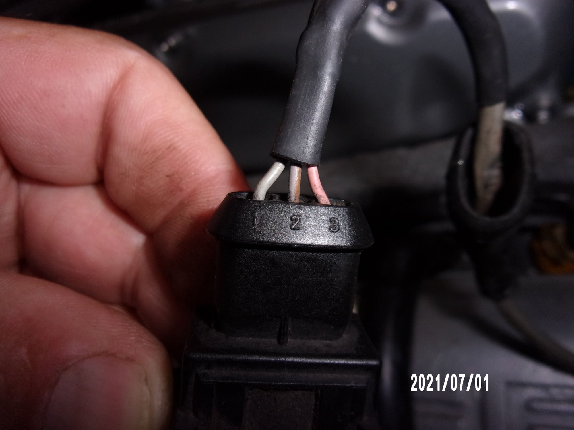
Got to the car today and took the hall sensor connector apart and ohm'd the cable that goes to the EZK From the hall sender and also checked for short to ground Here is the connector from the hall sender red 1, green 2, black 3 correct orientation
If you put them together ... Looks OK to me. Let me know if you see and discrepancy between the two My assumption is the hall sender is bad. Would I heck the signal with the oscilloscope ground to signal
Thank you John, I will back probe for voltages (Or can I safely check that in the female plug with the hall sender disconnected) before checking for the signal from the sender.

 05-26-2021, 07:01 PM