When you click on links to various merchants on this site and make a purchase, this can result in this site earning a commission. Affiliate programs and affiliations include, but are not limited to, the eBay Partner Network.
4 pins on the Mahle/Behr - Pin 1 is ground, Pin 2 is PWM signal, Pin 3 to motor and Pin 4 is Batt/12V. So you would need a pwm generator to use it and figure out which pin is 1.
4 pins on the Mahle/Behr - Pin 1 is ground, Pin 2 is PWM signal, Pin 3 to motor and Pin 4 is Batt/12V. So you would need a pwm generator to use it and figure out which pin is 1.
Thanks that's useful! I think this is the path I'd use to do this with a separate PWM controller.
I'd not really want the power section in the console - it will still get rather hot so more airflow is good (there is ~none in the console) and it will also create some switching noise - so better its the other side of the firewall from the radio front end.
I'd also be inclined to mount a large decoupling cap and series inductor (LC network) with TVS right near the final drive unit to both suppress noise and to be kind to the motor and alternator/regulator.
For an electrically challenged person like me who is looking for a solution for the 928 community how does this "simple" solution work with our HVAC?
Alan can you help?
I really don't want this Post to die and live in the archives.
Like Roger, I am still not sure what the wiring is to get this PWM to work on our cars when the time comes (and it will come)
It has power in and power out (should be labelled on the PCB)
All you need to do is find the wires for full power from the switch and wire that is in line between the switch and the fan.
You can probably connect it at the original resistor pack location or inside the car through the factory switch wiring as it will have both positive connections. I just cannot remember the pinout of it.
It's easy to connect it so it would work - but compatibility with the existing controls (control location) & wiring is not so easy - will require some reconfigurations.
50 posts in...and still ignoring now simple and reliable the original resistor assembly is....
And how well it functions, for it's intended task.
If the resistor pack was a failure that occurred every few years or if it wasn't so easy to repair, "dreaming up" a replacement would be one thing. However, these things last 25 years to infinity, before they have an issue, and 99% of them can be returned to normal function in 20-30 minutes.
It's incrediblely rare to find an original resistor pack with one of the coils detached...and as long as this isn't the case, these things are repairable...virtually forever.
Clean the pack. Clean the contact points. Separate the contact points, by about .5mm. Re-install, for another 25 years....
Greg speaks the truth. The original mechanism is pretty decent stone age technology. It can even be rebuilt if you can find the right gauge Nichrome wire if the coils have burnt out.
Here is where I am and why I am perched on the edge of the rabbit hole of fabricating a replacement.
My resistor pack is squeaky clean and the coils are all within spec for resistance. Roger's replacement blower motor went in 4 or 5 years ago and draws about 20 amps going full blast and less than 5 in the "off" position. As my wife demands "Ice Station Zebra" in the summer months, my AC system, including the evaporator and all ducts, is clean. Air movement is not an issue. The gap on my bimetallic strip contact points is greater than .05 millimeter and the points have been filed (still miss my 71 Firebird Formula 400 with breaker points). Turn on the car, wait a few, and whoosh. Magic Blower.
So unless the amperage I am seeing is off the charts, either the male or feminine side of my bimetallic strip is out of whack. I don't have a replacement part and nobody else does either.
Option 1 - Take the female 8 pin connector at the resistor apart and move the pin that carries current to the blower when the strip contacts close (maximum kludge).
Option 2 - Bend the bimetallic strip and unspecified amount, find the melting point of the thinnest gauge wire in the resistor pack, see if the strip closes at 75% of that temperature, reinstall and hope for the best. I imagine, but don't know, that the strip is there to prevent the coils from getting hot enough to ignite debris in the duct rather than protect the coils, but have no clue what the temperature would be. (semi-rational kludge)
Option 3 - Dive in the rabbit hole and complete fabricating an upgrade.
I am leaning towards option 2 but because I am a lunatic and others have asked what I have learned, here's what I can share for those suffering with similar types of insanity:
1. Types of components that are going to be needed :
A. Something to step down 12 volts from the HVAC switch down to 5 volts. This is what I found:
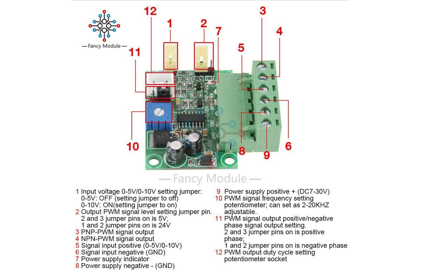
C. High Amp capable PWM motor driver like this volvo unit - Ebay
D. Resistors or potentiometer to vary input to the PWM module to control fan speed. A pot would allow any speed you select like your modern daily driver.
E. Weatherproof project box, eight pin connector from junkyard 80's Mercedes, stuff
In theory the 5V output of the PWM converter goes to the appropriate pin in the motor driver which converts that low voltage low current signal into corresponding high current PWM output to the blower. The PWM frequency is important because motors may not like low frequency PWM and have a sweet spot. The controller linked above has adjustable frequency output and other features that I am still too ignorant to explain as I know what PNP and NPN are but haven't a clue beyond that.
I have a PWM radiator fan control I pulled from a Mazda that's rated for 85 Amps, but it's really to big for the duct.
If you want to get really nuts, you can substitute an arduino nano microcontroller for the PWM converter and program it to incorporate soft start and other features. Also, you would not have to build a resistor network if your car has the combination switch fan control. The arduino could simply be programmed to change the PWM when each of the analog input pins fed by the switch goes high.
This is, I think, a feasible approach but fairly painful. Depending on your view of the Chinese electronics industry, it might be pretty bulletproof.
Welcoming input from other lunatics and electron wranglers with superior knowledge.
Thanks
Last edited by Eplebnista; 02-21-2023 at 03:32 PM.
Option 4 - buy a resistor pack for the '87 - '93 that only has a series thermal switch. These have no magic blower mode - if the resistor pack overheats the fan just switches off [there is a simpler (replaceable) series thermal switch]. You do need to reconfigure a few pins on the connector - but it is not difficult.
In this case obviously used is the way to go - the good news - there is less chance of any latent issues with this kind of blower resistor. The older style is questionable used because you only find out if the bimetallic strip switch is really OK after running it for a while in the car.
I was hoping for some news on this front. Kicking myself for not replacing it before NLA. Liking Greg's idea on refurbishing used. Anyone thinking about providing this as a service.
Mark possibly has a decent supply of used units. Perhaps refusrbished used units are the way to go. I'm getting tired of the all or none blower switch.
Possibly I could do this myself with a decent right up on the subject. Anyone care to share instructions with pictures?
Just to confirm - all the Resistor packs apart from the 94/95 pack are NLA.
A modern replacement would be awesome.
Alan - can 928 616 101 02 be adapted to be backward compatible as you found out on 928 616 101 00.
I have one here if you want to experiment - happy to send it to you.
Rose passion has the resistors for the older cars.
I was hoping for some news on this front. Kicking myself for not replacing it before NLA. Liking Greg's idea on refurbishing used. Anyone thinking about providing this as a service.
Mark possibly has a decent supply of used units. Perhaps refusrbished used units are the way to go. I'm getting tired of the all or none blower switch.
Possibly I could do this myself with a decent right up on the subject. Anyone care to share instructions with pictures?
That would be cool.
Thanks
My blower was only working on high as well and I was about to pull the trigger on a new one last spring when Roger still had them available, but decided to attempt a repair first since I felt I had nothing to lose.
I removed the metal cage by carefully bending up the retaining tabs. Then liberally sprayed the coils with DeoxIT and lightly scrubbed with an old toothbrush. Finally and I'm sure this was probably the real issue; I cleaned the contacts (similar to points on an old distributor) with some fine grit sandpaper. Put the cage back on, re-installed in resistor and had full function of the blower switch again.
I am easily intimidated by electrical issues and repairs but this fix was much easier than I had expected and was probably more mechanical than electrical. My only regret was not tackling it sooner.

 12-19-2022, 09:44 PM