When you click on links to various merchants on this site and make a purchase, this can result in this site earning a commission. Affiliate programs and affiliations include, but are not limited to, the eBay Partner Network.
Thinking of alternative to the NLA Resistor pack. Easiest solution would seem to be Pulse Width Controller (PWC) (like used on condenser fans) with simple resistor bridge input to keep our manual fan speed switch, and convert the switch positions to analog volts out. And keep all the modification work in the HVAC tunnel.
The PWC units will handle the nominal 30A load, and the resistor bridge would be small 1/4W, soldered to the existing power plug. Or there may be a bridge device already out there for our use.
May even convert existing condenser ON/OFF, to PWC, based on refrigerant pressures. As the condenser wiring seems to be a weak point, and lower amps, for most of the time
I've managed to acquire 9 of the 928s, in all conditions, 4 drivers, two more nearly drivers, all needy. So the above is more of a fleet solution.
Thoughts?
The resistor configuration is wired to be switched on the positive side. Most PWM controls will want to be on the ground side in order to reduce load switching thermal dissipation - this is not an easy fix.
Are you sure the resistor pack is NLA - alternate years can be substituted with relatively minor connection changes
Alan
Alan,
Appreciate if you can expand a bit on why such would be difficult.
Given Porsche used PWM technology on the 87+ models it would seem to be a sensible approach especially if the resistor pack is no longer available
MOSFETS need a gate voltage significantly higher than their drain voltage in order to be fully saturated so they can operate in a low power switching mode (needed for practical PWM operation). The only configuration that easily allows this is to put the switching on the ground side of the motor drive circuit and that is what most do. Alternatively you need a significantly sized charge pump to reach a gate drive voltage of ~20V (the late model cooling fan controller does this). The car is not configured this way stock (all resistor switching is on the positive side) so a significant rewiring would be needed. The PWM control needs either an adaptation to the blower switch or for a potentiometer to be used as a replacement control. Vehicle blower PWM solutions usually also have a high speed (sometimes multiple speeds) bypass mechanism as a backup to the PWM system - so some provision for a full speed bypass would be good. This would also provide a means to support the DEF mode blower max bypass. All in all its quite a of of work - including of course mounting the MOSFET heatsink somewhere - possibly in the plenum - but that would take a custom adaptation too. It is certainly doable and is indeed very typical of many/most modern cars - but the conversion from a 1970's configuration is not for the faint of heart. I have considered it, but for me its a challenging project - difficult to do quickly on a daily driver - there aren't really any functional intermediate stages for this installation. And I really need the blower to work if I'm to drive the car - YMMV.
MOSFETS need a gate voltage significantly higher than their drain voltage in order to be fully saturated so they can operate in a low power switching mode (needed for practical PWM operation). The only configuration that easily allows this is to put the switching on the ground side of the motor drive circuit and that is what most do. Alternatively you need a significantly sized charge pump to reach a gate drive voltage of ~20V (the late model cooling fan controller does this). The car is not configured this way stock (all resistor switching is on the positive side) so a significant rewiring would be needed. The PWM control needs either an adaptation to the blower switch or for a potentiometer to be used as a replacement control. Vehicle blower PWM solutions usually also have a high speed (sometimes multiple speeds) bypass mechanism as a backup to the PWM system - so some provision for a full speed bypass would be good. This would also provide a means to support the DEF mode blower max bypass. All in all its quite a of of work - including of course mounting the MOSFET heatsink somewhere - possibly in the plenum - but that would take a custom adaptation too. It is certainly doable and is indeed very typical of many/most modern cars - but the conversion from a 1970's configuration is not for the faint of heart. I have considered it, but for me its a challenging project - difficult to do quickly on a daily driver - there aren't really any functional intermediate stages for this installation. And I really need the blower to work if I'm to drive the car - YMMV.
Alan
Alan,
Thanks for the input. I am aware of the driving voltage concept- I kind of figured that maybe a stock PWM fan unit could be used if the ampage rating is adequate.
There are a variety of OEM PWM cooling fan controllers out there that rely on PWM control signals from the engine management computer to control cooling fans. These are robust units for bigger loads than the blower motor and employ different fail-safe strategies (i.e. loss of signal from computer equals full on) . You could use an Arduino Nano microprocessor to translate analog to PWM to send signals to the blower controller or purchase a board that does the same thing like this one: [url=http:// [ame]https://www.amazon.com/gp/product/B07YZ3LKP6/ref=ox_sc_act_title_4?smid=AWD4L551SADGP&psc=1 ]Analog to PWM[/ame] - it would seem that you could replicate the resistance for each step of the fan control to provide varying input to the board and set things within the duty cycle range of the OEM fan controller.
The existing resistor pack is NLA and Mark Anderson has some used for $100 which will fail sooner rather than later. OEM's have been making PWM fan controllers for decades.
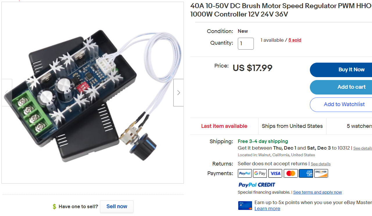
A PWM can work by substituting the variable resistor with 3 fixed resistors that each correspond to the appropriate / desired fan speed. These 3 resistors can be electronically swapped in to the circuit with a separate daughter board controlled but the in-cabin fan switch using 3 SPST micro relays. It might also be possible to simplify design and use 1 SPDT and 1 SPST relays to get the 3 positions.
Something like whats shown below could be worked in to the existing resistor pack space and hang in to the air flow like a blade for cooling.
Last edited by icsamerica; 11-28-2022 at 10:11 PM.
The load can be controlled from the ground side, as the fan doesn't care. A simple resistor bridge wired to the speed inputs, available at the resistor pack, could provide the speed steps required.
Just looking down the road for solutions as the resistor packs were old technology, when Porsche choose the approach. I'll look into some available PWM controllers.
Just to confirm - all the Resistor packs apart from the 94/95 pack are NLA.
A modern replacement would be awesome.
Alan - can 928 616 101 02 be adapted to be backward compatible as you found out on 928 616 101 00.
I have one here if you want to experiment - happy to send it to you.
__________________
Does it have the "Do It Yourself" manual transmission, or the superior "Fully Equipped by Porsche" Automatic Transmission? George Layton March 2014
928 Owners are ".....a secret sect of quietly assured Porsche pragmatists who in near anonymity appreciate the prodigious, easy going prowess of the 928."
1. Mercedes W114 / W123 seems like a close enough drop in replacement. Stands to reason, the MB blower motor is similar and lots of other MB parts can be found on a 928.
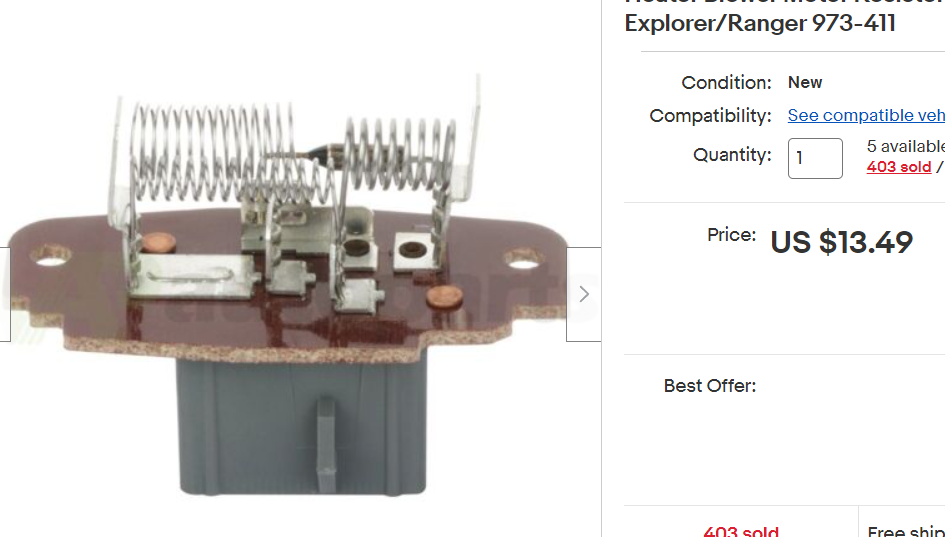
2. Chop, cut rebuild. Seems like Ford Range resistor pack could be used as a donor to rebuild a failed OE 928 resistor pack.
Crude the resistor packs may be....but they very rarely fail from a resistor coil going bad.
Almost all can be repaired by cleaning the contact faces of the overheat mechanism, making them completely functional for another 30 years....
Semi-retired, as of Feb 1, 2023.
The days of free technical advice are over.
Free consultations will no longer be available.
Will still be in the shop, isolated and exclusively working on project cars, developmental work and products, engines and transmissions.
Have fun with your 928's people!
Crude the resistor packs may be....but they very rarely fail from a resistor coil going bad.
Almost all can be repaired by cleaning the contact faces of the overheat mechanism, making them completely functional for another 30 years....
How does cleaning the contact faces fix the problem? If one has "magic blower syndrome" the contact faces on the overheat mechanism are clearly working. I've heard of people bending the mechanism in a certain way in order to prevent the bimetallic strip protection circuit from coming in early which is not a good idea in my view. Best to solve the problem and change the aged out blower fan motor that draws too much current and repair / replace the resistor pack if it has become compromised from carbonization and burning from the hot glow of persistent over heating.
All that considered it might also be a good idea to check the ground and change the 12v supply wire from the Central electrical panel to the fan and have a look at the fuse socket. Both of these items can age fail and stack resistance which drops voltage and increases current draw. My love affair with Jaguar's and Lucas wiring has taught me that even though a length of wire looks good on the out side it can be internally corroded in such a way that it effectively become a resistor. In this case a DVM is your friend. You can measure the resistance in a length of wire which no-one does becasue it's a simple wire and that's seem silly but it's not. Then its also a good idea to measure voltage when loaded at the source (CEP) and at the end point, (blower motor on high). Should be very little voltage drop, if the drop is significant then a fresh wire of the popper gauge is needed. That will bring the voltage back up, allow the fresh fan motor to run efficiently and should solve magic blow syndrome so long as air flow is sufficient to cool a working resistor pack.
Last edited by icsamerica; 12-01-2022 at 12:46 AM.
"How does cleaning the contact faces fix the problem? "
Resistance?
U'mmm No! The contacts are open until the resistor pack over heats, then the the bimetallic strip bends and closes the contacts creating a circuit that by-passes the resistor pack making the fan run at full speed. This allows the restore pack to cool from air flow and from not being utilized to reduce the fan speed.
Such a suggestion on your part demonstrates a fundamental lack of understanding of how the item in question actually functions. Which is no surprise to me.

 11-28-2022, 12:59 PM


 George Layton March 2014