When you click on links to various merchants on this site and make a purchase, this can result in this site earning a commission. Affiliate programs and affiliations include, but are not limited to, the eBay Partner Network.
here's an oversimplified version: air going through the intake system creates vacuum. The HVAC system uses that vacuum to move the hot water control valve and all the flaps that direct air throughout the interior. One black hardish small vacuum line runs from the intake on a 928 engine, though the firewall near the brake booster, and to the HVAC distribution system under the dash / near your right leg at the center console.
the HVAC distribution system consists of electric swtiches that open vacuum to different flaps according to the commands sent from the control unit (what you see on the dashboard).
the system defaults to full hot water, and airflow to the defroster vents if there is no vacuum (because unhooked or bc a leak).
since your system does not appear to be hooked to the engine, it will default to full hot water.
the first thing you need to do is find the black vacuum line that would connect the system to the engine. then figure out where to hook it up (advice already given above).
once you have the black line, you can use a little hand vacuum pump (like a mity-vac) and test the system to see if all the flap controllers work.
this link will show testing, and the very first photo shows the hardish black line that goes through the firewall
I took apart the center console and tested each actuator then hooked up the little pump in place of vacuum from the engine. In my case the actuators were OK but a lot of the hose ends were just not sealing well.
Thanks for the info! I will start debugging it and post again as I run into problems. Any chance you know where the best place to hook up the test pump into the system where the engine would hook up?
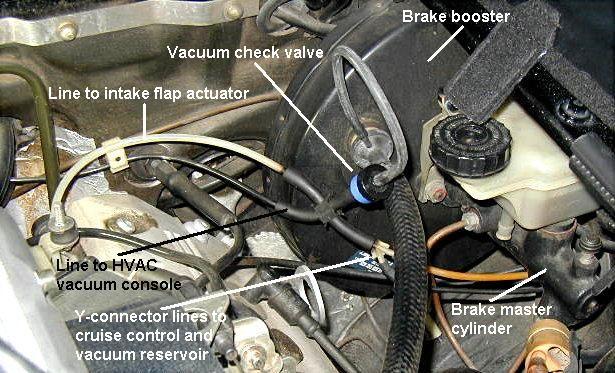
In my car there is a T in the large diameter vacuum hose to the brake booster, I don't remember if that was a factory part or one I added. The small diameter hose that came off the T spread out to all the rest of the vacuum system. The black hard line in the picture is a good place to start with a test pump. The white hard line in the picture goes to the heater control valve.
I believe the tan or white line coming out of the firewall visible in your picture is the line to the heat control valve. The line into the HVAC controls is a black plastic line that plumbs into the brake booster line.
As your car was an automatic, there will also be a line going to once was the vacuum modulator on the transmission.
This may help some as well:
Ok, you need to fix all of the leaking vacuum actuators in the dash that are part of the HVAC system...you get no vacuum because it's all an open leak.
I don't see where the OP posted any pictures of what's under his dash. Is Rennlist censoring photos or did they somehow get deleted?
Thank you for that picture. I found the black vacuum line at the firewall. I think it got broken off at some point during the swap, so it is pretty short. When I get the mini vacuum pump for testing I will hook it up and let everyone know how it goes.
Good news! I got the test pump and hooked it up to the black line and the system works again! Now I just need to run a new vacuum line from the LS intake and back to the black line. There is one thing that is a little odd and I feel like it has to do with the temperature sensor. The valve to divert coolant does not close unless I turn the system off, meaning I slide the vent selector all the way to the left. This happens even if I have the heat setting all the way cold. I have a feeling it might be because I am in Michigan and it is colder than the lowest heat setting in my garage (it was about 50 degrees in the garage this morning). I will test it again when it warms up in a few weeks.
Again, thank you everyone for your help and input on this!
Probably your external temp sensor which is in the left fender, either open circuit or removed during the swap. I guess you don’t have the original alternator with the cooling tube which is where it’s fitted. The WSM has a procedure for testing the sensors or there’s a ton of thread here on the subject.
I looked in the fender area and found where the wires were cut. I am planning to just put a resistor between the wires to fake it out. Thank you again for the help!


 03-12-2023, 03:25 PM