When you click on links to various merchants on this site and make a purchase, this can result in this site earning a commission. Affiliate programs and affiliations include, but are not limited to, the eBay Partner Network.
Looking for ignition switch wire location in the CE
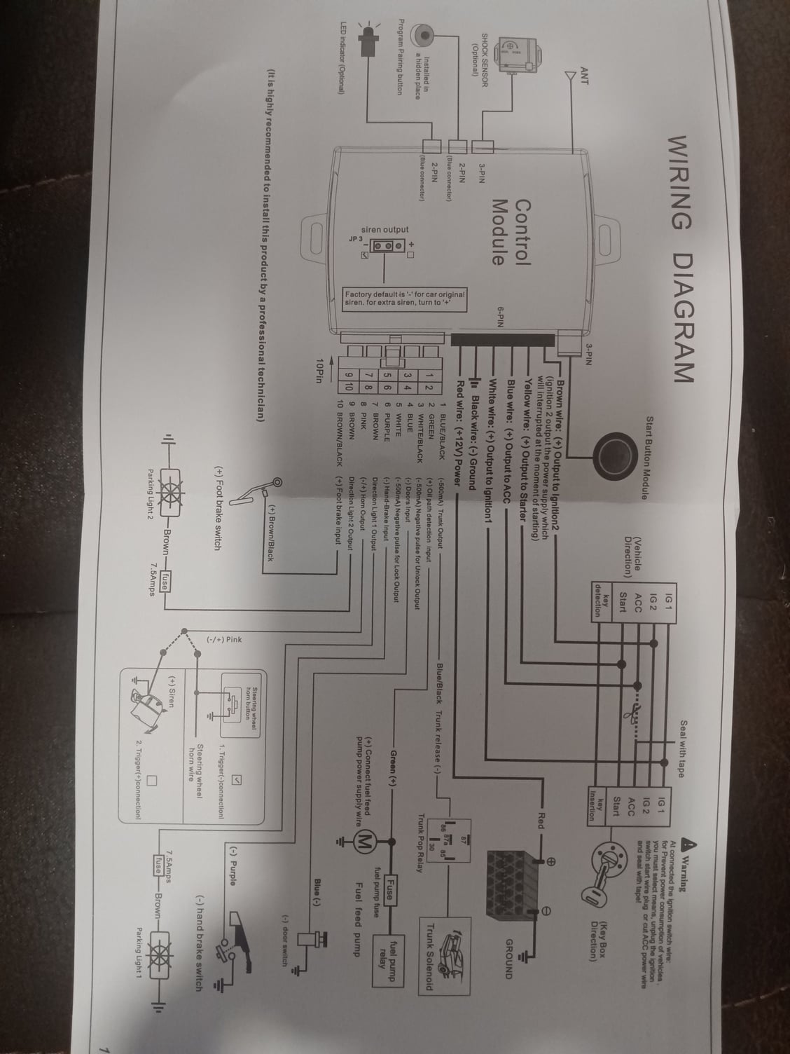
Hello fellas. 87 auto. Looking for the block and pin location of ignition key wires on the CE. This is what I do know from using the search function. Thanks. Yes I do have the shop manuals. Looking at the wiring diagram. I might as well be trying to read Chinese LOL.
Reds are battery in (30)
Blacks are Ignition out (15) (on in position 2 & 3 only)
Yellow is Starter(relay)(50) (on in positions 3 only)
Black/Yellows are Accessories(X) (on in positions 1 & 2 only)
Red/Black(thick) is Radio Supply (on in Positions 1,2,3)
Red/Black(thin) is power in (30) to key-in switch
Grey is Off (on in Position 0 - key in or out)
Black/Red is key-in switch output(*) (on when key is in)
Switch Position
* Key Out
0 Inserted only
1 Accesssory Only
2 Ignition
3 Starter
OF THE IGNITION SWITCH CONNECTIONS (note these CE locations are different for most other years).
===================================:
Reds are battery in - always on (30) - [Comes from the battery+ - These are always also the big red wires bolted on top of the CE panel on all 1985+ cars] Blacks are Ignition out (15) (on in position 2 & 3 only) - [On an 87 These are the top connections on Fuses 7 - 13 and also on CE pins: B11, B12, B13, B15, B21, B22, B23, Q11, Q12] Yellow is Starter (via relay) (50) (on in position 3 only) - [On an 87 this is on CE Pin: A23] Black/Yellows are Accessories(X) (on in positions 1 & 2 only) - [On an 87 These are the top connections on Fuses 1 - 5 and also on CE pin: A22] Red/Black(thick) is Radio Supply (R) (on in Positions 1,2,3) - [Does not go to CE panel - goes only to the radio/head suppressor] Grey - Parking light power (P) (on only in Positions */0 Key in or out) - [Does not go to CE panel - goes only to the combo switch]
Red/Black(thin) is power in to key-in switch (terminal 1) - [on an 87 this is on CE Pin: E11 (also goes to dash) (this is a fused (30) supply)]
Black/Red Key-in switch terminal 2 (on in Position 0 with Key inserted) - [Does not go to CE panel - goes only to timer/chime relay]
Switch Position * Key Out 0 Key Inserted only 1 Accesssory Only 2 Ignition 3 Starter
The CEB wire terminals in diagrams are identified with a letter and 2 digits. The letter for the connector and digits for the wire terminal. Each CEB connector has 2 rows of 5 terminals side by side. From bottom to top, left side terminals are 11,12,13,14 and 15. From bottom to top, right side terminals and 21,22,23,24 and 25.
By the way. Do you know if anybody has already traced out all the wires and labeled them on that CE panel diagram that you showed? I know in my research one guy actually asked. He had all the relays labeled but was questioning the wiring so he could label that.
By the way. Do you know if anybody has already traced out all the wires and labeled them on that CE panel diagram that you showed? I know in my research one guy actually asked. He had all the relays labeled but was questioning the wiring so he could label that.
No - it is different for every year, and despite what you may think it would not actually make it much clearer. You'd know where all those wires went - but that mostly isn't final equipment so you just moved the unknown to the next level - but still unknown. The secret is the magic decoder ring so you can understand the diagrams - well its a little more complicated than that - But here: Porsche 928 Wiring Diagram Primer
These questions all pertain to the circuits leaving the CE panel
Where does the .......
1.fuel pump feed ?
2. hazard lights ?
3. Horn?
Last question.
Back feeding the CE panel to power the various positions of the ignition switch. Do I have to hit each individual circuit that comes on via switch position or one circuit per switch position and that will back feed the rest?
Thanks
You appear to be trying to do something, but this is a very slow reveal... Based on what you have said so far I question if you understand enough to debug whatever this is? The Ignition switch only has one input (30). Everything else is an output. If you suspect the ignition switch isn't working the correct test is to see if its outputs switch as expected - and if not simply replace the electrical part of the switch. "Backfeeding" the ignition switch is useful for what? doing this wrongly could cause damage and seems quite unnecessary
If you have a specific fault you'd like help debugging tell us what that is in as much detail as possible.
There's no fault at all. Installing a remote start. I have two options to do this. Tie parallel into the ignition switch wiring harness. Which requires me to remove the dash pod. I really do not want to tie into that wiring harness. Other option is to come off the CE panel via the block wires. This option would allow me to easily troubleshoot any problems or remove the unit all together if a problem occurs.
the unit has outputs to power all 4 key positions. It needs input from the 12v feed to the fuel pump. It will also need to send 12v to hazard lites and horn.
So with this last bit of information I can start to research whether this route will work for me.
Just a little background . I've owned the car for over 20 years. I've done all the maintenance work. pretty much rebuilt everything on the car that a PO would have to do. Rebuilt my CE panel. Only thing I have not mastered is how to read the schematic LOL.
Fuel Pump on an '87 is on CE Pin U15
Horn on an '87 is on CE Pin P23
However there are still some complexities:
1) There is no Hazard connection to make all 4 turn signals flash (the Hazard switch does that by shorting L & R sides together when activated) - so you have to connect to L & R via diodes or temporarily connect L & R together with a relay similar to how the switch does. Perhaps you have dual separate flasher outputs on the remote start?
Turn Signal Right on an '87 is on CE Pin C24 (this is before the 2 fuses - to maintain fuse protection & cover both front & rear)
Turn Signal Left on an '87 is on CE Pin C23 (this is before the 2 fuses - to maintain fuse protection & cover both front & rear)
With key out & in off (position */0) the car is set up to enable parking lights based on the turn signals stalk position and this will continue to happen unless a key is in and the ignition is not in position 0. For normal operation you need to intercept and disable this when running. The car is designed to start with Accessories (X) off - it will start with accessories on but the load on the battery will be a lot higher (dual cooling fans, HVAC fan, compressor clutch, rear demister, etc) so not ideal for cold morning starts (possibly the remote start already accommodates for this?).
Allen given your knowledge of the 928 electrical system. Looking at the schematic. what would be the best locations to tap into as far as the CE panel to feed the ignition accessories?
Also would like to add that this does come with push button start which I will be using.
Alan sorry for missing your name. I hit send a little to fast before proofreading. It seems as though everything is getting very small on this cell phone LOL. guess my eyes are starting to go

 10-13-2023, 10:30 PM