
Differential adjusments
 02-06-2005, 08:01 PM
#1
Addict
Rennlist Member
Rennlist Member
Thread Starter
While we have two manual gearboxes in middle of stripdown we have tried to take measurements of critical dimensions while taking out parts. As we do not have factory special tools have had to improvise something that simulates them. Would like to get comments are these anywhere near same as what factory tools measure.
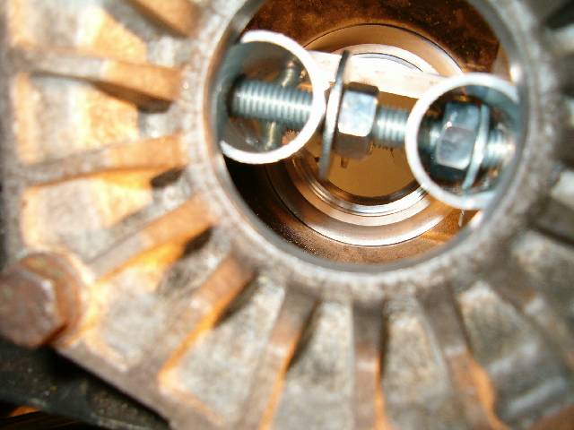
First backlash on '85 S G28/10. WSM page 39-227 says to use several special tools and measure from side of transmission. We made hook for holding pinion from flat steel as instructed.
Figured special tools have to measure ring gear rotation movement. Only question is what exactly, it is direct movement or some value that is in some unknown ration of visible ring gear movement. To test this we attached normal measuring clock (not sure of proper english name) to gearbox case using flat steel to mount magnetic arm.
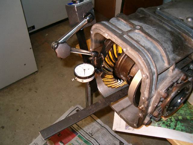


Ring gear has backlash value F 0.18 in it, by coincidence same as in WSM example. When we attached measuring device so that it measured teeths movement as directly as possible from edge to edge is gives 0.18mm. Either we were incredibly lucky and got same result as gear says by measuring totally different thing or this is easy way of replacing all those expensive tools. Can it be so simple? Why did factory spend all the money on special tools if couple of backwoods mechanics without any formal traning using only of the shelf tools can achieve same results?
It gets weirder still. To find out if pinion gear of '92 G28/57 is in position where numbers in ring gear says it should be we decided to build very grude measuring device from aluminium pipe, threaded bar, nuts and washers. AFAIK value E in ring gear is distance (in mm) from pinion gear surface to imaginary line running from center of one sideplate to other. To mount the 'tool' we removed bearings outer race from sideplates. Tool is not pretty.
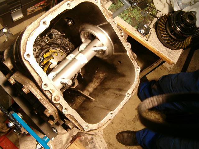
Original plan was to have both nuts in between two pipes but pipe diameter was too large for that. Nuts we thightened by hand only so that pipes would not make any marks on sideplates (they didn't).
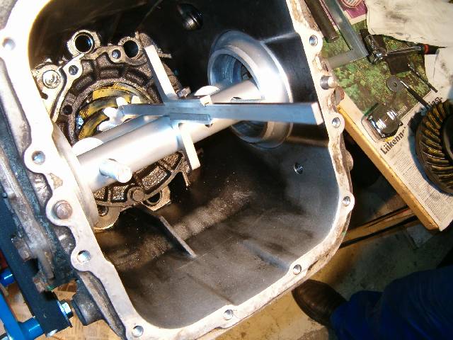
Pipes were aligned so that measurement was same from top and bottom side. It took some time to set them so that it was same but seems it was worth it. Side to side position of measuring tool on rearmost pipe was checked by making sure it was equal distance from both walls of gearbox case. Other end of tool was centered to pinion gear just visually by using gears small center dimple as quide. We also measured distance from pipe to pipe, this gave how wide they are together so that it could be used in calculation. We did measurement, dismantled pipes almost totally, put them back together and measured again. Same results on both times.
Now the interesting part is that from rear pipes behind to surface of pinion gear distance was 111.00mm and pipe packages diameter was 80.00mm. Both were measured more than once. If my math is correct this is formula to get pinion gear surface to imaginary center measurement:
111.00mm - (80.00mm / 2) = 71.00mm
In ring gear it says E70.97 meaning our result is only 0.03mm of.
Can it be possible to get so close with so grude methods or did we get incredibly lucky twice? I have always thought all those factory special tools are really needed to be able to set 928 differential correctly to quiet running spot. I know our numbers can't be accurate to 0.01mm but if they are to 0.1mm it seems setting S1, S2, S3 and S5 shims can be done with tools costing well under $100 rather than over $2000. Please prove me wrong before we use these tools in putting these two boxes back together.
First backlash on '85 S G28/10. WSM page 39-227 says to use several special tools and measure from side of transmission. We made hook for holding pinion from flat steel as instructed.
Figured special tools have to measure ring gear rotation movement. Only question is what exactly, it is direct movement or some value that is in some unknown ration of visible ring gear movement. To test this we attached normal measuring clock (not sure of proper english name) to gearbox case using flat steel to mount magnetic arm.
Ring gear has backlash value F 0.18 in it, by coincidence same as in WSM example. When we attached measuring device so that it measured teeths movement as directly as possible from edge to edge is gives 0.18mm. Either we were incredibly lucky and got same result as gear says by measuring totally different thing or this is easy way of replacing all those expensive tools. Can it be so simple? Why did factory spend all the money on special tools if couple of backwoods mechanics without any formal traning using only of the shelf tools can achieve same results?
It gets weirder still. To find out if pinion gear of '92 G28/57 is in position where numbers in ring gear says it should be we decided to build very grude measuring device from aluminium pipe, threaded bar, nuts and washers. AFAIK value E in ring gear is distance (in mm) from pinion gear surface to imaginary line running from center of one sideplate to other. To mount the 'tool' we removed bearings outer race from sideplates. Tool is not pretty.
Original plan was to have both nuts in between two pipes but pipe diameter was too large for that. Nuts we thightened by hand only so that pipes would not make any marks on sideplates (they didn't).
Pipes were aligned so that measurement was same from top and bottom side. It took some time to set them so that it was same but seems it was worth it. Side to side position of measuring tool on rearmost pipe was checked by making sure it was equal distance from both walls of gearbox case. Other end of tool was centered to pinion gear just visually by using gears small center dimple as quide. We also measured distance from pipe to pipe, this gave how wide they are together so that it could be used in calculation. We did measurement, dismantled pipes almost totally, put them back together and measured again. Same results on both times.
Now the interesting part is that from rear pipes behind to surface of pinion gear distance was 111.00mm and pipe packages diameter was 80.00mm. Both were measured more than once. If my math is correct this is formula to get pinion gear surface to imaginary center measurement:
111.00mm - (80.00mm / 2) = 71.00mm
In ring gear it says E70.97 meaning our result is only 0.03mm of.
Can it be possible to get so close with so grude methods or did we get incredibly lucky twice? I have always thought all those factory special tools are really needed to be able to set 928 differential correctly to quiet running spot. I know our numbers can't be accurate to 0.01mm but if they are to 0.1mm it seems setting S1, S2, S3 and S5 shims can be done with tools costing well under $100 rather than over $2000. Please prove me wrong before we use these tools in putting these two boxes back together.
 02-06-2005, 08:27 PM
#2
Rennlist Member
Well, if you havent disturbed the pinion set up yet (ie still as it left factory), and there is no detectable slack in its bearings, AND your arithmetic and logic of using depth tool is right, I would expect you should get a close answer. These are setups whose only test is in eating the result. If you change pinion bearings and your measurements say you need to change shims etc, when its all back together and runs quietly, and no other issues appear, you got it right. The backlash dial gauge needs to have its rod as near to right angles as possible to the crown wheel tooth to get good reading - was your test done BEFORE disturbing the bearings, or after?
jp 83 Euro S AT 48k
jp 83 Euro S AT 48k
02-06-2005, 08:38 PM
#3
Addict
Rennlist Member
Rennlist Member
Thread Starter
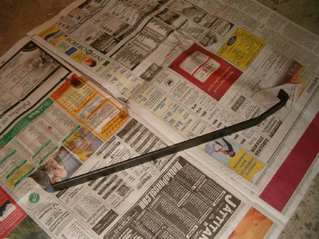
G28/10 backlash testing was done before sideplates were touched. In fact they are still in. We take G28/57 internals out first. Angle in picture isn't exacly right. We played with several different ones and one where dial gauge was pointing even upwards seemed good way of measuring as teeth pushed gauge more directly.
02-06-2005, 10:56 PM
#4
Drifting

For the backlash... I can't tell from the photo if you have it right, but you should point the dial indicator toward the plane of the tooth contact surface.
For the pinion placement.... you want to measure the WSM Ro dimension. You really don't need that tool you made but it should work. I'd just measure from the cover plate gasket surface, take measurements and caluclate the offset from the Ro origin (center of the drive shaft).
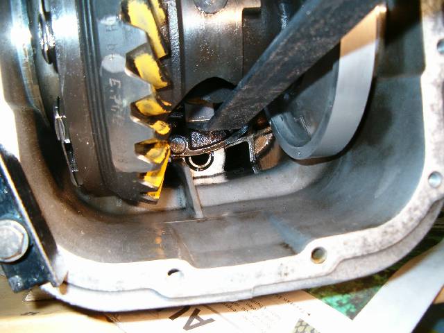
On your pinion lock tool... if you find you have some pinion bearing play, then you might want to correct that first, otherwise your backlash will not be quite right. One way to tell if you have pinion bearing play, you'll be able to watch the dial indicator jump when you lock the pinion gear with the tool.
For the pinion placement.... you want to measure the WSM Ro dimension. You really don't need that tool you made but it should work. I'd just measure from the cover plate gasket surface, take measurements and caluclate the offset from the Ro origin (center of the drive shaft).
On your pinion lock tool... if you find you have some pinion bearing play, then you might want to correct that first, otherwise your backlash will not be quite right. One way to tell if you have pinion bearing play, you'll be able to watch the dial indicator jump when you lock the pinion gear with the tool.
02-07-2005, 10:41 AM
#5
Addict
Rennlist Member
Rennlist Member
Thread Starter
Gauge was in fore aft direction compared to gearbox cage. In up down direction it was as close as possible against teeth surface what it measured. We reasoned that way it would give most accurate measurement. If gaude were pointing directly up from gear teeth surface in my opinion it would not measure rings rotation in correct direction and results would be sightly off.
We made pipe tool as we reasoned it measures distance using same points as factory tool. Cover plate surface could have worked equally well but we wanted to be sure we get as close to factory way as possible.
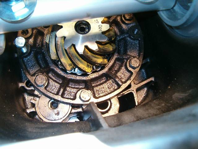
There didn't seem to be any fore aft play in pinion gear. Gauge reading didn't change at all when pressure was aplied. So far whe have seen only one problem in both boxes. It's clearly caused by bad design and seem to affect all '85 and later manual gearboxes. More on this later when we have G28/10 enough open to have faulty parts out.
We made pipe tool as we reasoned it measures distance using same points as factory tool. Cover plate surface could have worked equally well but we wanted to be sure we get as close to factory way as possible.
There didn't seem to be any fore aft play in pinion gear. Gauge reading didn't change at all when pressure was aplied. So far whe have seen only one problem in both boxes. It's clearly caused by bad design and seem to affect all '85 and later manual gearboxes. More on this later when we have G28/10 enough open to have faulty parts out.
03-05-2005, 09:20 PM
#6
Addict
Rennlist Member
Rennlist Member
Thread Starter
We measured pinion placement on '85 S box today. Did it two ways. Used pipes like in previous pictures and bar across cover plate gasket surface.
Pipes gave:
111.10mm - (80.00mm / 2) = 71.10mm
Cover surface gave:
184.50mm - 73.35mm - (80.00mm / 2) = 71.15mm
In ring gear it says E71.12 meaning our result is only -0.02mm or +0.03mm of. Not bad.
Pipes gave:
111.10mm - (80.00mm / 2) = 71.10mm
Cover surface gave:
184.50mm - 73.35mm - (80.00mm / 2) = 71.15mm
In ring gear it says E71.12 meaning our result is only -0.02mm or +0.03mm of. Not bad.

