
Instrument Cluster Repair w/pics (Part II)
 04-26-2008, 01:46 PM
#1
Rennlist Member
Thread Starter
Join Date: Sep 2007
Location: Ridgecrest, California
Posts: 1,363
Likes: 0
Received 143 Likes
on
28 Posts
I had been experiencing problems with my fuel gauge not registering full when I filled up (only 3/4) and my speedometer started malfunctioning (only worked when the sun heated up the pod). After a lot of troubleshooting to narrow it down to the instrument cluster, I decided to remove the pod (for the first time) and try cleaning the connections on the instrument cluster.
Here's the list of tools I used to work on the instrument cluster:
1) Standard (flat blade) screwdriver
2) Phillips screwdriver
3) 7mm Nut Driver
4) Pliers
5) Soldering Iron and Electrical Solder
6) Electronics Cleaner and Q-Tips
7) Pink Eraser
8) Ohm Meter
9) Selectable AC to DC converter
10) Small Flexible Snake Light (optional for viewing instrument warning lights)
I've included a few pictures for others (like myself) that have never done this before - so this is a Noobie-rated procedure.
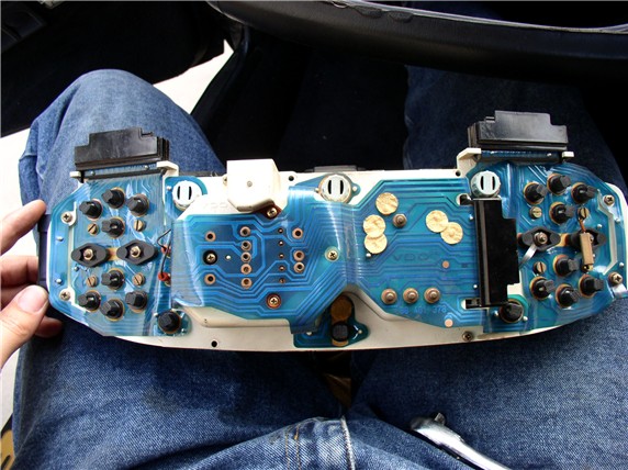
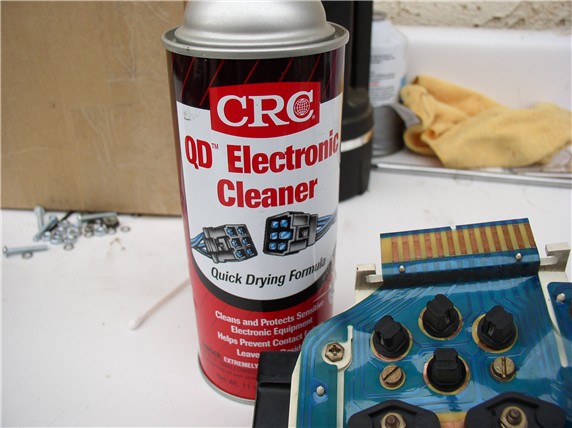
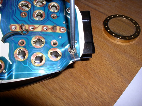
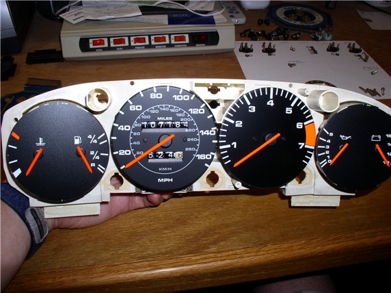
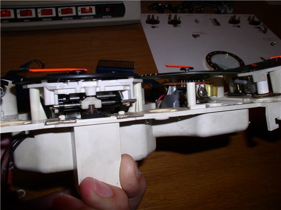
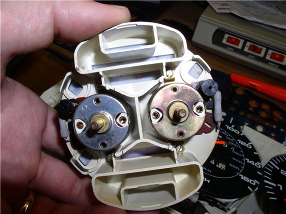
Here's the instrument cluster once it's been separated from the pod. This is for the 1984.
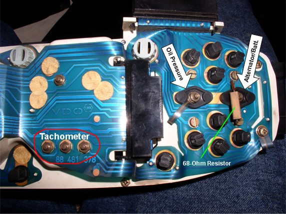
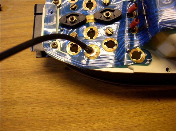
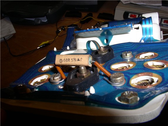
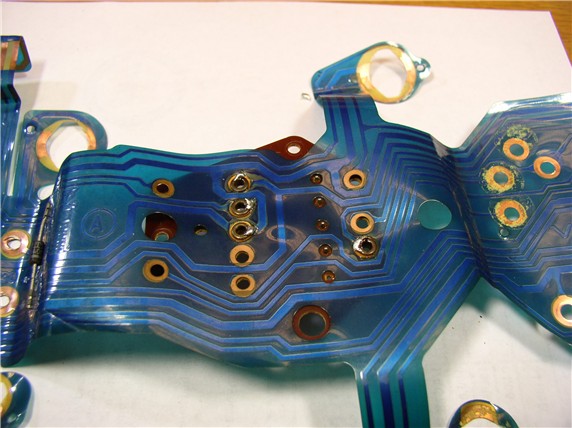
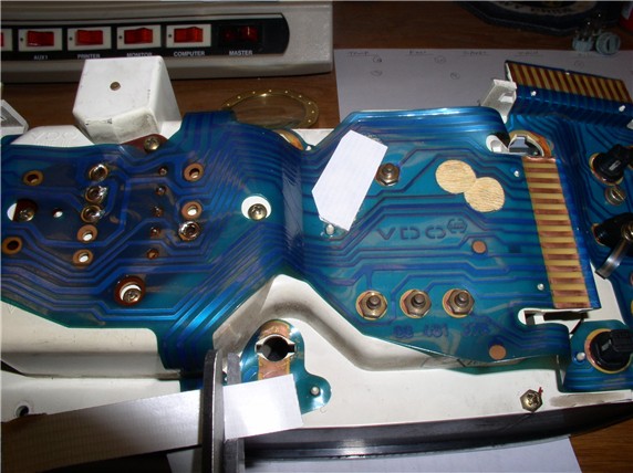
Here's where the right-hand instruments are located looking at the back side. There was a 68 Ohm resistor over the alternator/batt gauge.
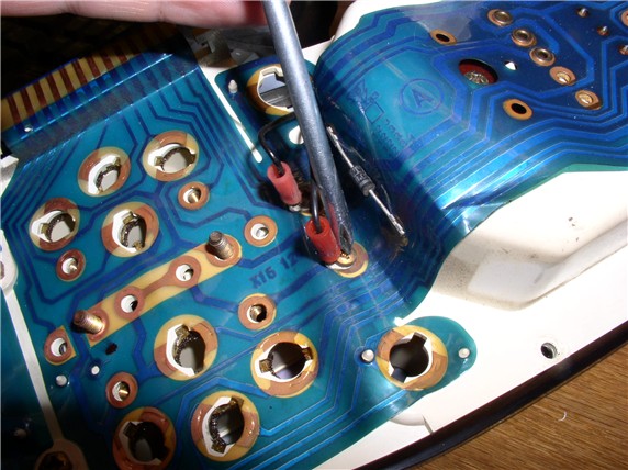
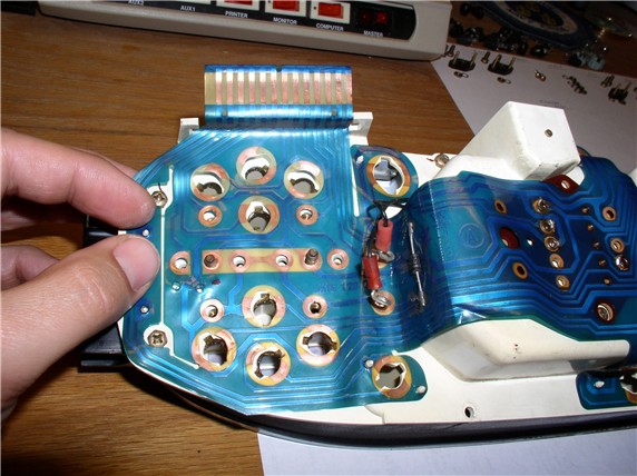
On the left-hand side were the two problem areas for me: Fuel and Speedometer. So I mapped which signals were coming into the speedometer at the identified rivets at the back of the speedo. The two red connectors with wires attached that run under the speedo cover are for speedometer reset.
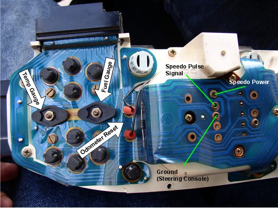
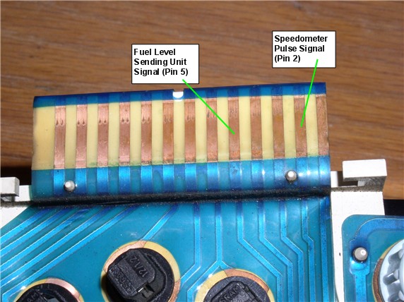
The Fuel level sending unit signal and speedometer pulse signals arrive through pins 5 and 2, respectively on the left-hand wiring harness connector. I found this by tracing the wiring diagrams that I got with Jim Morehouse's CD of Technical Treasures - GREAT reference!
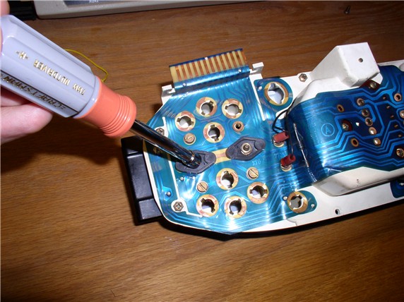
I planned to simply clean all the connectors first and test to see if I got any improvement. I've been using the CRC Electronics Cleaner.
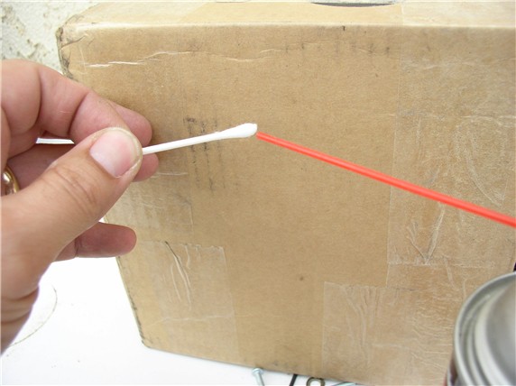
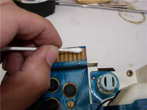
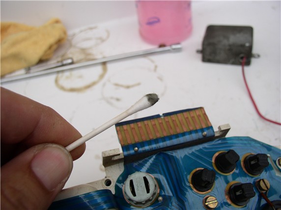
In order to get a good cleaning, I used q-tips (soaked in the CRC cleaner) to clean the connectors....
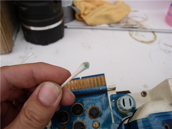
On some pins, I got a light greenish residue...
On some other pins, I got a black residue....
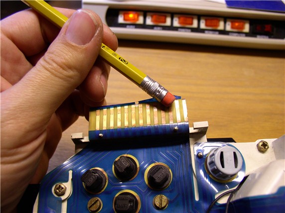
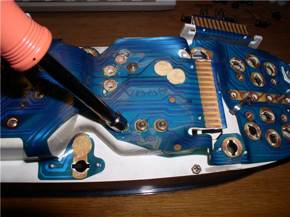
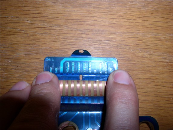
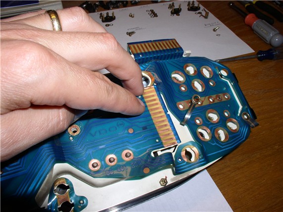
Even after the cleaning with the CRC and Q-tips, the connectors didn't look very clean. So I decided to use a pink eraser. The trick here is to hold the plastic circuit board firmly in place with your fingers while using the eraser so as not to wrinkle or crease the plastic.
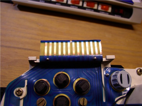
After the eraser cleaning, the contacts looked a lot cleaner.
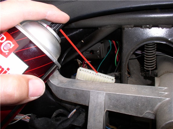
I then went to the harness and inspected the connectors there and sprayed with the CRC as well. These connectors all looked very clean to begin with.
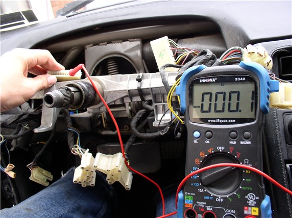
Finally, I checked the wiring harness end-to-CEB connections for continuity and got something like 0.1 ohms. I even tried jostling the wires while checking to see if there were any intermittent problems. Everything checked out fine.
At this point, I put the instrumentation cluster back into the car (without the pod) and connected up the 3 wiring harness connectors. Then reconnected the battery and started the car. BTW, I had filled the fuel tank to capacity before starting this repair so I expected the fuel gauge to register full if everything was functioning properly.
I seemed to actually see some slight improvement in the fuel gauge - it showed a little above the 3/4 but not at full. I also drove the car and the speedometer showed no improvement - still would not function. However, I noticed that with the back of the instrument cluster exposed, I could lightly touch the connections (rivets) at the back of the speedometer and when I did, the speedometer acted erratically - doing all sorts of funky things.
So, it looked like I would have to go further with the repair and do some soldering. I parked the car, disconnected everything and brought the cluster in the house for disassembly.
Continued.....
Here's the list of tools I used to work on the instrument cluster:
1) Standard (flat blade) screwdriver
2) Phillips screwdriver
3) 7mm Nut Driver
4) Pliers
5) Soldering Iron and Electrical Solder
6) Electronics Cleaner and Q-Tips
7) Pink Eraser
8) Ohm Meter
9) Selectable AC to DC converter
10) Small Flexible Snake Light (optional for viewing instrument warning lights)
I've included a few pictures for others (like myself) that have never done this before - so this is a Noobie-rated procedure.
Here's the instrument cluster once it's been separated from the pod. This is for the 1984.
Here's where the right-hand instruments are located looking at the back side. There was a 68 Ohm resistor over the alternator/batt gauge.
On the left-hand side were the two problem areas for me: Fuel and Speedometer. So I mapped which signals were coming into the speedometer at the identified rivets at the back of the speedo. The two red connectors with wires attached that run under the speedo cover are for speedometer reset.
The Fuel level sending unit signal and speedometer pulse signals arrive through pins 5 and 2, respectively on the left-hand wiring harness connector. I found this by tracing the wiring diagrams that I got with Jim Morehouse's CD of Technical Treasures - GREAT reference!
I planned to simply clean all the connectors first and test to see if I got any improvement. I've been using the CRC Electronics Cleaner.
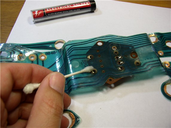
In order to get a good cleaning, I used q-tips (soaked in the CRC cleaner) to clean the connectors....
On some pins, I got a light greenish residue...
On some other pins, I got a black residue....
Even after the cleaning with the CRC and Q-tips, the connectors didn't look very clean. So I decided to use a pink eraser. The trick here is to hold the plastic circuit board firmly in place with your fingers while using the eraser so as not to wrinkle or crease the plastic.
After the eraser cleaning, the contacts looked a lot cleaner.
I then went to the harness and inspected the connectors there and sprayed with the CRC as well. These connectors all looked very clean to begin with.
Finally, I checked the wiring harness end-to-CEB connections for continuity and got something like 0.1 ohms. I even tried jostling the wires while checking to see if there were any intermittent problems. Everything checked out fine.
At this point, I put the instrumentation cluster back into the car (without the pod) and connected up the 3 wiring harness connectors. Then reconnected the battery and started the car. BTW, I had filled the fuel tank to capacity before starting this repair so I expected the fuel gauge to register full if everything was functioning properly.
I seemed to actually see some slight improvement in the fuel gauge - it showed a little above the 3/4 but not at full. I also drove the car and the speedometer showed no improvement - still would not function. However, I noticed that with the back of the instrument cluster exposed, I could lightly touch the connections (rivets) at the back of the speedometer and when I did, the speedometer acted erratically - doing all sorts of funky things.
So, it looked like I would have to go further with the repair and do some soldering. I parked the car, disconnected everything and brought the cluster in the house for disassembly.
Continued.....
 04-26-2008, 02:37 PM
#2
Rennlist Member
Thread Starter
Join Date: Sep 2007
Location: Ridgecrest, California
Posts: 1,363
Likes: 0
Received 143 Likes
on
28 Posts
In order to remove the plastic laminated circuit board, first remove the bulbs. There were two types of bulbs - the indicator/warning bulbs (black plastic) and the instrument illumination bulbs (grey plastic). The indicator/warning bulbs are removed by twisting counterclockwise 90 degrees and lifting up.
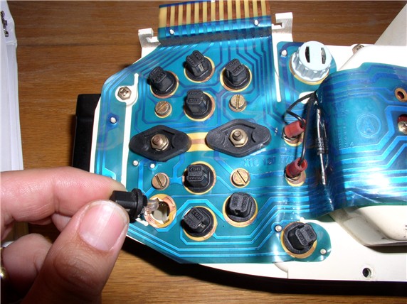
The instrument illumination bulbs are removed in the same manner - there were three of these.
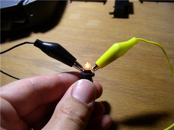
Once you get the bulbs out, it's a good idea to test each one to see if it is working properly. I used an AC/DC converter that had selectable output DC voltages. I set it to 9 Volts and connected the power leads to the bulb connections on opposite sides. After checking all the indicator/warning bulbs, I found I had one that was burnt out and another that was very dim - So I ordered a couple of replacements from 928 Intl.
I checked the illumination bulbs as well and all three checked out. However, new replacement bulbs for these were only $1 each, so I went ahead and replaced them with new and kept the old for replacements.
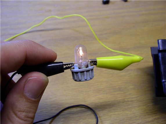
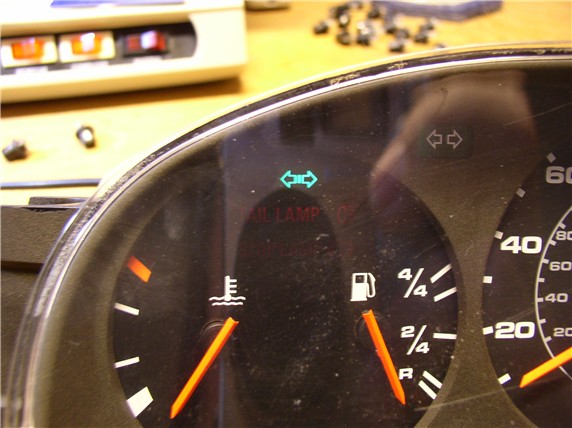
Just for fun, when you get the bulbs out, you can use a thin snake light to illuminate each of the indicator/warning cavities and see what warnings you've got but maybe never seen before.
Here's a signal indicator I've never seen illuminated before. Turns out it seems to be for a trailer turn signal contact when towing something (according to the wiring diagram).
Next, remove the standard flat blade screws. There are two for each of the four gauges and each screw has a small washer.
There is a 68-Ohm resistor attached to the screws by the Alternator/Batt gauge on my '84. The washers were located underneath the resistor wires.
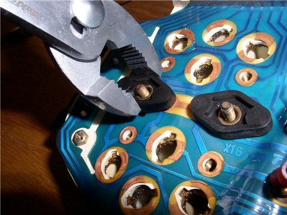
Then remove each of the 7mm nuts that hold the gauges in place and connected to the instrument cluster enclosure.
Once the nuts and small washers are off, you can use a pair of pliers to carefully grab the sides of the plastic diamond-shaped connector and work it back and forth while pulling up.
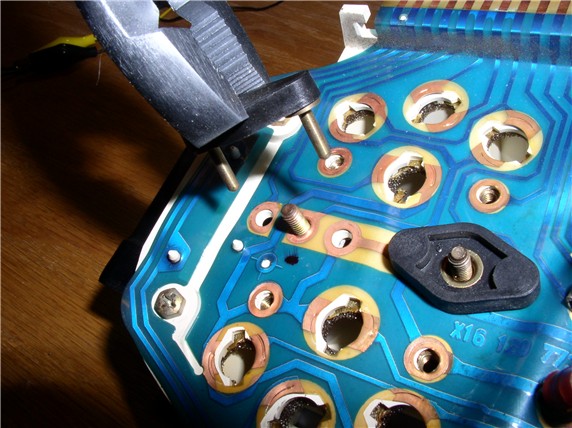
Next, you can remove the 7mm nuts that hold the tachometer in place - there are four of these (also with washers).
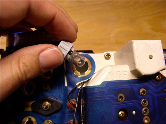
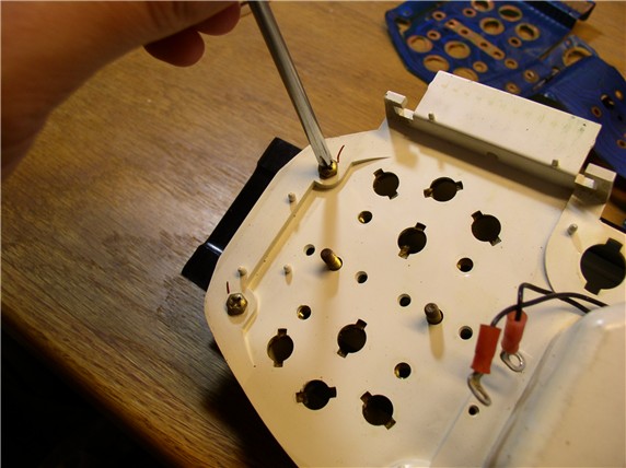
The odometer reset screws are next. They take a phillips screwdriver. I had to slightly bend flat the connectors in order to get the phillips screwdriver in place. It's a good idea to mark one of the connection wires in case they get mixed up. I marked the top wire at the red plastic casing with a "T" using a sharpie.
The speedometer screws are next. They take a phillips screwdriver. The speedometer also has a hard circuit board that is riveted to the plastic circuit board through four rivets. So in order to remove the plastic circuit board, the hard circuit board must come off too. There are two screws that hold the hard circuit board to the plastic instrument enclosure.
Do not try to lift the hard circuit board out just yet.
Continued....
The instrument illumination bulbs are removed in the same manner - there were three of these.
Once you get the bulbs out, it's a good idea to test each one to see if it is working properly. I used an AC/DC converter that had selectable output DC voltages. I set it to 9 Volts and connected the power leads to the bulb connections on opposite sides. After checking all the indicator/warning bulbs, I found I had one that was burnt out and another that was very dim - So I ordered a couple of replacements from 928 Intl.
I checked the illumination bulbs as well and all three checked out. However, new replacement bulbs for these were only $1 each, so I went ahead and replaced them with new and kept the old for replacements.
Just for fun, when you get the bulbs out, you can use a thin snake light to illuminate each of the indicator/warning cavities and see what warnings you've got but maybe never seen before.
Here's a signal indicator I've never seen illuminated before. Turns out it seems to be for a trailer turn signal contact when towing something (according to the wiring diagram).
Next, remove the standard flat blade screws. There are two for each of the four gauges and each screw has a small washer.
There is a 68-Ohm resistor attached to the screws by the Alternator/Batt gauge on my '84. The washers were located underneath the resistor wires.
Then remove each of the 7mm nuts that hold the gauges in place and connected to the instrument cluster enclosure.
Once the nuts and small washers are off, you can use a pair of pliers to carefully grab the sides of the plastic diamond-shaped connector and work it back and forth while pulling up.
Next, you can remove the 7mm nuts that hold the tachometer in place - there are four of these (also with washers).
The odometer reset screws are next. They take a phillips screwdriver. I had to slightly bend flat the connectors in order to get the phillips screwdriver in place. It's a good idea to mark one of the connection wires in case they get mixed up. I marked the top wire at the red plastic casing with a "T" using a sharpie.
The speedometer screws are next. They take a phillips screwdriver. The speedometer also has a hard circuit board that is riveted to the plastic circuit board through four rivets. So in order to remove the plastic circuit board, the hard circuit board must come off too. There are two screws that hold the hard circuit board to the plastic instrument enclosure.
Do not try to lift the hard circuit board out just yet.
Continued....
04-26-2008, 03:26 PM
#3
Rennlist Member
Thread Starter
Join Date: Sep 2007
Location: Ridgecrest, California
Posts: 1,363
Likes: 0
Received 143 Likes
on
28 Posts
The final screw holding the platic circuit board in place was in the corner and was one of 6 screws used to connect the instrument enclosure backing to the front of the enclosure.
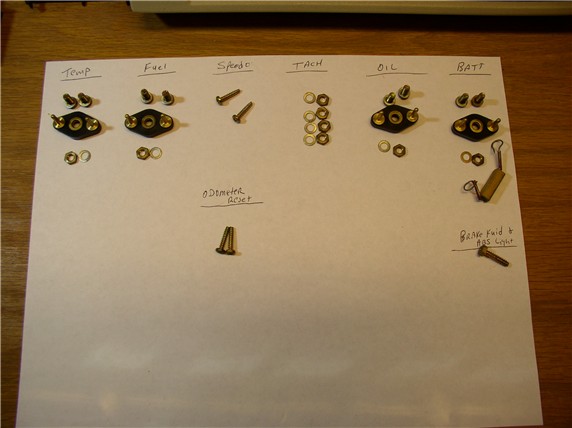
Since this was my first time, I thought it was a good idea to keep all the hardware organized as to where it came from. It can all easily fit on an 8.5" X 11" sheet of paper.
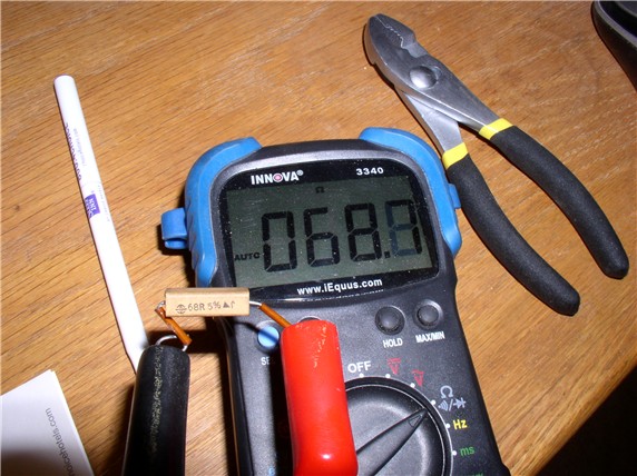
Since you have the one resistor off, it would be a good idea to test it with an ohm meter. This one seemed to check out OK - 68.7 Ohms on the meter while the resistor seemed to indicate 68 Ohms rating marked on the casing.
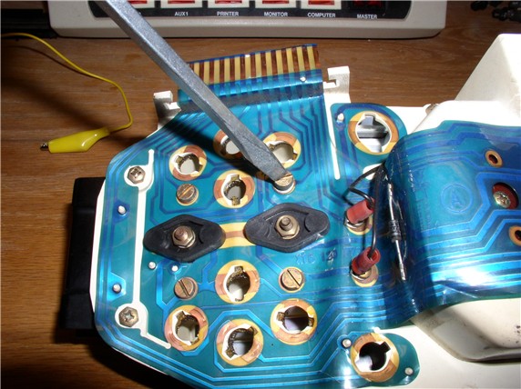
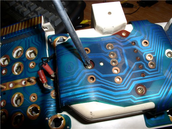
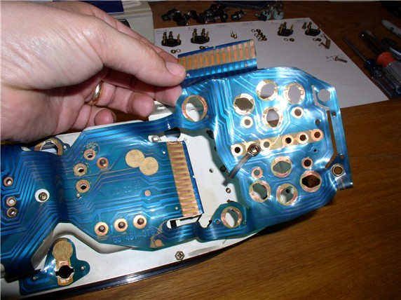
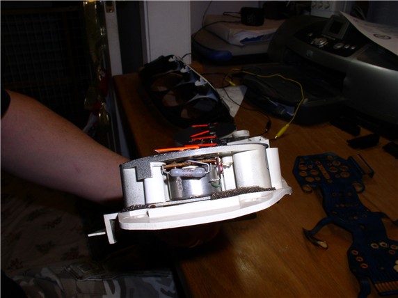
Now you can begin removing the plastic circuit board from the back of the instrument enclosure. I started with the the left side. There are small platic pins facing upward that mate up with punched holes in the plastic laminate. They were pretty snug so gently lift up from each of the retaining pins by lifting up from opposite sides of the pin.
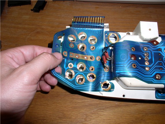
...and the same with the other side - leaving the center still attached.
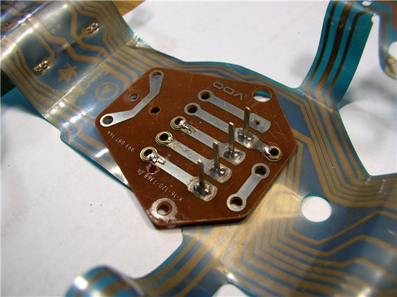
To get the hard circuit board out, you can use a small flat blad screwdriver to gently pry the board up from underneath. There are four long pins that connect down into the speedometer so you will want to lift straight up as much as possible so as not to bend the pins.
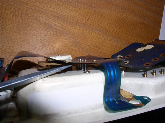
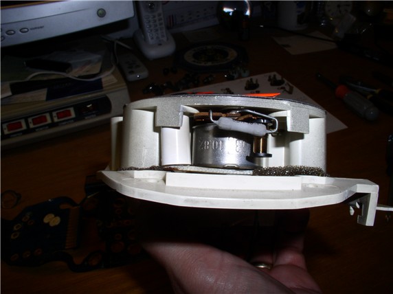
Once the board is out, you can separate the plastic laminated board from the instrument cluster.
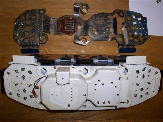
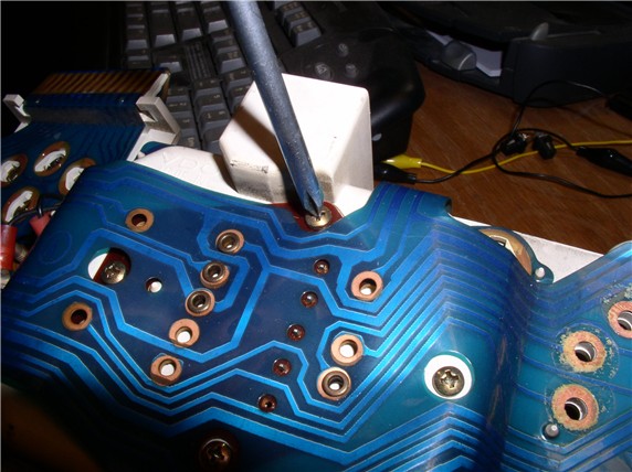
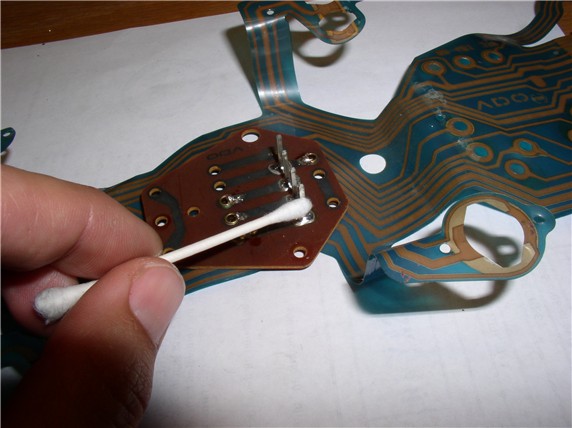
Next you can clean all exposed copper contact areas with the pink eraser. Remembering to hold the plastic firmly in place while erasing so as not to crease the plastic board.
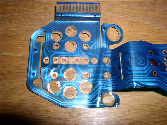
I noticed on the harness connections some very small writing in what looked like german. Unforntunately, I can't read german (except I noticed one word - looked like blinker). I'm assuming they identify the pin connections.
Next comes the soldering. I'm a Noob at soldering - only soldered a handful of times previously. So I was a little concerned about melting holes in the plastic or short circuiting something will solder spill over. When I was ordering my bulbs from Jim at 928 Intl, he offered a non-functioning plastic circuit board to practice with - no charge! THANKS Jim!
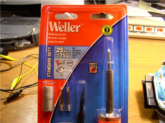
I found the practice piece a great way to experiment with soldering techniques. At first, I started out with a 15watt soldering iron. But it had a rounded tip (non replaceable) and took a long time to work with. So I bought a 25watt iron and kit with removable tips (about $17 at HD). I found the flat tips to work much better.
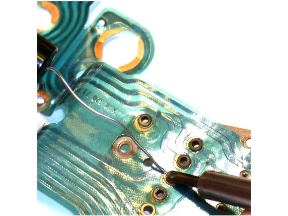
To solder the rivets, I placed the flat of the tip across the top and edge of the rivet and placed the solder on the edge of the rivet (not on the tip of the iron). It only takes a little bit of solder. The objective is to make contact with the rivet and the copper material embedded in the plastic laminate at the edge of the rivet.
Employ the same technique for soldering the rivets on the backside of the hard circuit board.
After I practiced some soldering with what I thought was great success, I tested the strength of the joint. Unforntunately, the solder easily came off when I pried the solder joint with a screwdriver. I forgot to clean the surface areas! Oh well, that's what practicing is for, right!
Rather than just use cleaner and a Q-Tip, I decided to really clean the rivet surface with a grinding stone tip on a dremel. You have to be very careful with this technique - if you slip off the rivet with any force, you could damage the plastic laminate. I used the slowest speed, took my time and applied very light force.
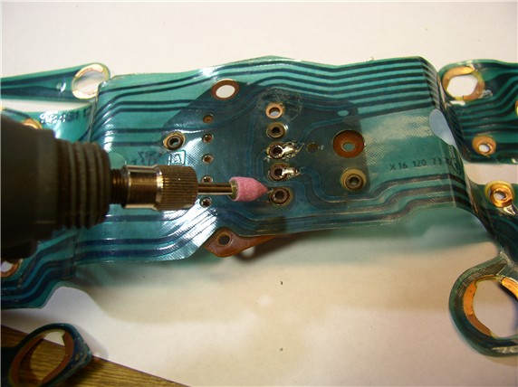
Here's the results of the cleaning with the dremel. This is probably a bit extreme for cleaning the surface of the rivets so if you're not comfortable with it or don't have a dremel, you could use a nail file, emry board/cloth, or fine sand paper. I reasoned that having a rougher surface would make a stronger solder.
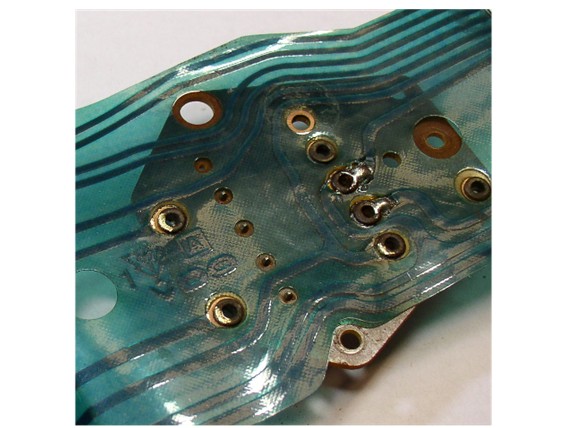
Before applying solder this time, I also cleaned the surrounding area with the electronics cleaner and Q-tip since I did not believe it to be a good idea to use an abrasive cleaning technique on the thin copper material embedded in the plastic laminate.
Continued....
Since this was my first time, I thought it was a good idea to keep all the hardware organized as to where it came from. It can all easily fit on an 8.5" X 11" sheet of paper.
Since you have the one resistor off, it would be a good idea to test it with an ohm meter. This one seemed to check out OK - 68.7 Ohms on the meter while the resistor seemed to indicate 68 Ohms rating marked on the casing.
Now you can begin removing the plastic circuit board from the back of the instrument enclosure. I started with the the left side. There are small platic pins facing upward that mate up with punched holes in the plastic laminate. They were pretty snug so gently lift up from each of the retaining pins by lifting up from opposite sides of the pin.
...and the same with the other side - leaving the center still attached.
To get the hard circuit board out, you can use a small flat blad screwdriver to gently pry the board up from underneath. There are four long pins that connect down into the speedometer so you will want to lift straight up as much as possible so as not to bend the pins.
Once the board is out, you can separate the plastic laminated board from the instrument cluster.
Next you can clean all exposed copper contact areas with the pink eraser. Remembering to hold the plastic firmly in place while erasing so as not to crease the plastic board.
I noticed on the harness connections some very small writing in what looked like german. Unforntunately, I can't read german (except I noticed one word - looked like blinker). I'm assuming they identify the pin connections.
Next comes the soldering. I'm a Noob at soldering - only soldered a handful of times previously. So I was a little concerned about melting holes in the plastic or short circuiting something will solder spill over. When I was ordering my bulbs from Jim at 928 Intl, he offered a non-functioning plastic circuit board to practice with - no charge!
THANKS Jim! I found the practice piece a great way to experiment with soldering techniques. At first, I started out with a 15watt soldering iron. But it had a rounded tip (non replaceable) and took a long time to work with. So I bought a 25watt iron and kit with removable tips (about $17 at HD). I found the flat tips to work much better.
To solder the rivets, I placed the flat of the tip across the top and edge of the rivet and placed the solder on the edge of the rivet (not on the tip of the iron). It only takes a little bit of solder. The objective is to make contact with the rivet and the copper material embedded in the plastic laminate at the edge of the rivet.
Employ the same technique for soldering the rivets on the backside of the hard circuit board.
After I practiced some soldering with what I thought was great success, I tested the strength of the joint. Unforntunately, the solder easily came off when I pried the solder joint with a screwdriver. I forgot to clean the surface areas! Oh well, that's what practicing is for, right!
Rather than just use cleaner and a Q-Tip, I decided to really clean the rivet surface with a grinding stone tip on a dremel. You have to be very careful with this technique - if you slip off the rivet with any force, you could damage the plastic laminate. I used the slowest speed, took my time and applied very light force.
Here's the results of the cleaning with the dremel. This is probably a bit extreme for cleaning the surface of the rivets so if you're not comfortable with it or don't have a dremel, you could use a nail file, emry board/cloth, or fine sand paper. I reasoned that having a rougher surface would make a stronger solder.
Before applying solder this time, I also cleaned the surrounding area with the electronics cleaner and Q-tip since I did not believe it to be a good idea to use an abrasive cleaning technique on the thin copper material embedded in the plastic laminate.
Continued....
04-26-2008, 04:08 PM
#4
Rennlist Member
Thread Starter
Join Date: Sep 2007
Location: Ridgecrest, California
Posts: 1,363
Likes: 0
Received 143 Likes
on
28 Posts
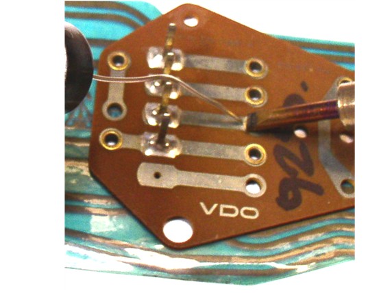
After the cleaning of rivets and surrounding area. I soldered again using the same techniques. I then tested the strength with the screwdriver and all the joints were solid. Here's the results on the practice piece.
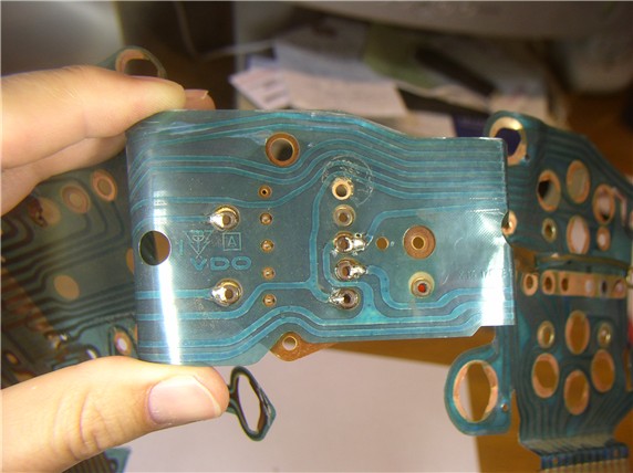
Then I moved to solder the REAL DEAL - I soldered the plastic side first.
Then solded the hard side (back side) next. I believe my practice piece actually turned out better then my final version!
At this point, I was done with the speedometer repair and it was time to move onto the fuel gauge. To get to the fuel gauge, you have to remove the front cover. It is held in place with 6 phillips screws (two at each end and two in the middle on my '84). One of these screws was already taken out when the plastic circuit board was removed.
Once the screws are out, hold the instrument cluster right side up (instruments facing upward toward the ceiling) and holding the back of the enclosure with one hand, lift up and remove the front cover with the other. The gauges can fall out if you hold the cluster with gauges facing down and remove the front cover because there's nothing holding them in at this point. I actually dropped my Fuel/Temp gauge on the floor at one point not realizing they were just lying in place with nothing holding them in.
Once you have the front cover off, you can inspect the innards of the cluster for anything that might look out of place - of course, since I don't know what I'm looking at, I couldn't tell if something was out of place or not! But I didn't notice any broken contacts or loose wires/connections and everything looked pretty clean.
On the gauges, you will notice resistors that will be labelled with their rating. You can test each of these with the Ohm Meter to make sure they check out. Mine all checked out. There was a 27 Ohm resistor at the Alternator/Batt gauge and 68 Ohm resistors elsewhere.
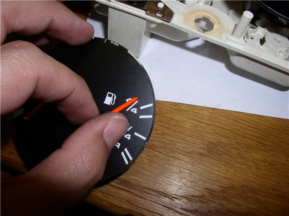
Since I couldn't find anything wrong with the fuel gauge, electrically, I decided I would simply adjust the needle about 1/8" up so that it would lie exactly on the full line of the gauge when the tank was full. To do this, remove the fuel/temp gauge by simply grasping at the outer edge and lifting up.
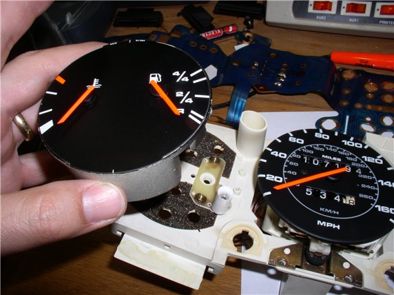
Here's a pic of the back side - nothing looked out of place.
To adjust the needle, grasp the center cap the needle is attached to (DO NOT GRASP THE NEEDLE ITSELF - IT CAN EASILY BEND) and rotate the needle to the furthest top position until you feel it stop. At this point, continue to rotate the center cap upward (counterclockwise) very carefully until you've achieved the movement desired. In order to better gauge how far the needle actually adjusted, mentally mark the at-rest position of the needle in relation to the fuel gauge markings or the low fuel warning light (that's what I used) then see where the needle rests after the adjustment. It's kind of an art but using this technique, I figured I had adjusted it the correct amount.
At this point, you're almost ready for reassembly. First, put the fuel/temp gauge back in place and re-attach the front cover of the instrument cluster - check for any debris that may have fallen into the front cover before securing it. Then set the cluster aside. Next, using the electronics cleaner and a Q-Tip, clean the pin connectors on the gauge securing posts...
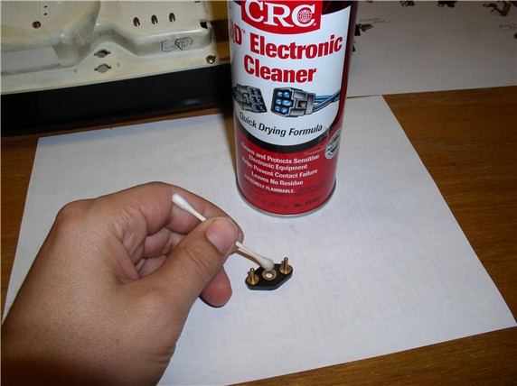
...and the pins on the speedometer hard circuit board.
Continued.....
Then I moved to solder the REAL DEAL - I soldered the plastic side first.
Then solded the hard side (back side) next. I believe my practice piece actually turned out better then my final version!
At this point, I was done with the speedometer repair and it was time to move onto the fuel gauge. To get to the fuel gauge, you have to remove the front cover. It is held in place with 6 phillips screws (two at each end and two in the middle on my '84). One of these screws was already taken out when the plastic circuit board was removed.
Once the screws are out, hold the instrument cluster right side up (instruments facing upward toward the ceiling) and holding the back of the enclosure with one hand, lift up and remove the front cover with the other. The gauges can fall out if you hold the cluster with gauges facing down and remove the front cover because there's nothing holding them in at this point. I actually dropped my Fuel/Temp gauge on the floor at one point not realizing they were just lying in place with nothing holding them in.
Once you have the front cover off, you can inspect the innards of the cluster for anything that might look out of place - of course, since I don't know what I'm looking at, I couldn't tell if something was out of place or not! But I didn't notice any broken contacts or loose wires/connections and everything looked pretty clean.
On the gauges, you will notice resistors that will be labelled with their rating. You can test each of these with the Ohm Meter to make sure they check out. Mine all checked out. There was a 27 Ohm resistor at the Alternator/Batt gauge and 68 Ohm resistors elsewhere.
Since I couldn't find anything wrong with the fuel gauge, electrically, I decided I would simply adjust the needle about 1/8" up so that it would lie exactly on the full line of the gauge when the tank was full. To do this, remove the fuel/temp gauge by simply grasping at the outer edge and lifting up.
Here's a pic of the back side - nothing looked out of place.
To adjust the needle, grasp the center cap the needle is attached to (DO NOT GRASP THE NEEDLE ITSELF - IT CAN EASILY BEND) and rotate the needle to the furthest top position until you feel it stop. At this point, continue to rotate the center cap upward (counterclockwise) very carefully until you've achieved the movement desired. In order to better gauge how far the needle actually adjusted, mentally mark the at-rest position of the needle in relation to the fuel gauge markings or the low fuel warning light (that's what I used) then see where the needle rests after the adjustment. It's kind of an art but using this technique, I figured I had adjusted it the correct amount.
At this point, you're almost ready for reassembly. First, put the fuel/temp gauge back in place and re-attach the front cover of the instrument cluster - check for any debris that may have fallen into the front cover before securing it. Then set the cluster aside. Next, using the electronics cleaner and a Q-Tip, clean the pin connectors on the gauge securing posts...
...and the pins on the speedometer hard circuit board.
Continued.....
04-26-2008, 04:33 PM
#5
Rennlist Member
Thread Starter
Join Date: Sep 2007
Location: Ridgecrest, California
Posts: 1,363
Likes: 0
Received 143 Likes
on
28 Posts
Now you can begin reassembly. Start by re-attaching the plastic circuit bard in the reverse order of taking it off. Start with the center where the speedometer pins press into the back of the speedometer. Then, press the plastic circuit board over the retaining pins on the back of the cluster housing.
It was easier to use two fingers around the retaining pin and pressing down until the plastic was flat agains the back of the cluster housing.
There were several small round holes that had factory tape over them (to prevent dirt/debris from entering the back of the tachometer, I suppose). The tape had lost its stickiness and they had come off. So I used some heavy duty fabric tape to cover the holes. I used some woven 2-sided tape and left the seal on one side of the tape. Masking tape didn't seem strong enough to stay and duct tape seemed a little over the top.
After all the nuts, screws and bulbs are replaced and the re-assembly complete, you can take it out to the car test it out by attaching the harnesses without the pod in place. After everything checks out, you can re-assemble the pod.
As far as the result of my repairs, it was very successful. The fuel gauge registered exactly on the top line when I tested it. And the speedometer works perfectly whether it's cold or hot - no more funky behavior. On the last outing, I decided to run the fuel low enough for the warning light to come on to see where the needle would be. This was the first time I've ever driven it until the warning light came on because I was never sure how much fuel I had in there before. The low fuel warning light came on when the needle was exactly between the lower two marks on the fuel gauge which seemed about right to me. I like the light coming on when the needle is right next to the bottom line on the fuel gauge.
I'll post a picture of the correctly functioning fuel gauge next time I fill up.
Please feel free to comment or provide suggestions for improvement. THANKS for reading!
It was easier to use two fingers around the retaining pin and pressing down until the plastic was flat agains the back of the cluster housing.
There were several small round holes that had factory tape over them (to prevent dirt/debris from entering the back of the tachometer, I suppose). The tape had lost its stickiness and they had come off. So I used some heavy duty fabric tape to cover the holes. I used some woven 2-sided tape and left the seal on one side of the tape. Masking tape didn't seem strong enough to stay and duct tape seemed a little over the top.
After all the nuts, screws and bulbs are replaced and the re-assembly complete, you can take it out to the car test it out by attaching the harnesses without the pod in place. After everything checks out, you can re-assemble the pod.
As far as the result of my repairs, it was very successful. The fuel gauge registered exactly on the top line when I tested it.
And the speedometer works perfectly whether it's cold or hot - no more funky behavior. On the last outing, I decided to run the fuel low enough for the warning light to come on to see where the needle would be. This was the first time I've ever driven it until the warning light came on because I was never sure how much fuel I had in there before. The low fuel warning light came on when the needle was exactly between the lower two marks on the fuel gauge which seemed about right to me. I like the light coming on when the needle is right next to the bottom line on the fuel gauge.I'll post a picture of the correctly functioning fuel gauge next time I fill up.
Please feel free to comment or provide suggestions for improvement. THANKS for reading!
04-26-2008, 05:15 PM
#6
Addict
Rennlist Member
Rennlist Member
Join Date: Mar 2003
Location: Idaho
Posts: 330
Likes: 0
Received 0 Likes
on
0 Posts
Great post Dwayne, thanks!
Given that the plastic circuit board is NLA for the '83/'84 models, this is very helpful.
The soldering of the rivets is something that never dawned on me...next time I pull the cluster I will be doing this.
Given that the plastic circuit board is NLA for the '83/'84 models, this is very helpful.
The soldering of the rivets is something that never dawned on me...next time I pull the cluster I will be doing this.
04-26-2008, 05:32 PM
#7
Rennlist Member
Excellent write ups Dwayne ! I think some of the problems you had with soldering could be eased with the addition of extra flux when soldering. There is some flux in the multicore solder you were using, but even though you cleaned the contacts as best as you could, some additional flux from a flux pen would probably have helped the solder to flow.
The contact cleaner I use is called a "contact cleaner lubricant" - this leaves a protective film to prevent further oxidisation which could be used for your final assembly after soldering. Your cleaner would be best before soldering as the protective film in mine would hinder solder flow.
The contact cleaner I use is called a "contact cleaner lubricant" - this leaves a protective film to prevent further oxidisation which could be used for your final assembly after soldering. Your cleaner would be best before soldering as the protective film in mine would hinder solder flow.
Trending Topics
04-26-2008, 08:26 PM
#8
Racer
Join Date: Sep 2007
Location: San Antonio, Texas
Posts: 264
Likes: 0
Received 0 Likes
on
0 Posts
Like all of your "How to" posts, this was excellent. I have a speedo problem as well and this will help.
Did you remove the fuel guage needle or just move it? I think I need to remove my speedo needle and do a little rehab on it when I get down and dirty with the instument cluster.
Thanks for posting and all the pictures.
Did you remove the fuel guage needle or just move it? I think I need to remove my speedo needle and do a little rehab on it when I get down and dirty with the instument cluster.
Thanks for posting and all the pictures.
04-26-2008, 10:42 PM
#9
Rennlist Member
Great write up and great pictures. I have just a few comments. 1. I agree with John Speake, a little flux will help the solder flow and you'll end up with much better connections and less solder on the joint. 2. The dremel is much to agressive. The flux alone will normally do the job , if not then some emmery cloth or very fine sandpaper. 3. You did a great job cleaning all the contacts, but you may have future contamination from the oil on your hands. I use latex or cotton gloves when handling these electronic boards or go to great lengths to avoid touching the contact areas.
Again great job!
Again great job!
04-27-2008, 12:25 AM
#11
Rennlist Member
Thread Starter
Join Date: Sep 2007
Location: Ridgecrest, California
Posts: 1,363
Likes: 0
Received 143 Likes
on
28 Posts
Excellent write ups Dwayne ! I think some of the problems you had with soldering could be eased with the addition of extra flux when soldering. There is some flux in the multicore solder you were using, but even though you cleaned the contacts as best as you could, some additional flux from a flux pen would probably have helped the solder to flow.
The contact cleaner I use is called a "contact cleaner lubricant" - this leaves a protective film to prevent further oxidisation which could be used for your final assembly after soldering. Your cleaner would be best before soldering as the protective film in mine would hinder solder flow.
The contact cleaner I use is called a "contact cleaner lubricant" - this leaves a protective film to prevent further oxidisation which could be used for your final assembly after soldering. Your cleaner would be best before soldering as the protective film in mine would hinder solder flow.
Thanks for the tip on extra flux. I'm a Noob when it comes to soldering so I didn't even know about using extra flux. You mention a flux pen - I wonder if this is something I can get at a hardware store like Home Depot?? I'll see if I can find it - then learn how to apply it - I still have the practice piece of plastic circuit board. I'd also like to see if I can find some of the Contact Cleaner Lubricant you mention - I haven't been treating any of my newly cleaned contacts but I like the idea of preserving them from contamination. THANKS!
Like all of your "How to" posts, this was excellent. I have a speedo problem as well and this will help.
Did you remove the fuel guage needle or just move it? I think I need to remove my speedo needle and do a little rehab on it when I get down and dirty with the instument cluster.
Thanks for posting and all the pictures.
Did you remove the fuel guage needle or just move it? I think I need to remove my speedo needle and do a little rehab on it when I get down and dirty with the instument cluster.
Thanks for posting and all the pictures.
I did not remove the needle - just moved it. I haven't tried to remove the needle, yet. THANKS for reading!
Great write up and great pictures. I have just a few comments. 1. I agree with John Speake, a little flux will help the solder flow and you'll end up with much better connections and less solder on the joint. 2. The dremel is much to agressive. The flux alone will normally do the job , if not then some emmery cloth or very fine sandpaper. 3. You did a great job cleaning all the contacts, but you may have future contamination from the oil on your hands. I use latex or cotton gloves when handling these electronic boards or go to great lengths to avoid touching the contact areas.
Again great job!
Again great job!
THANKS for the tips! Yes, I think the dremel is a bit over the top. On the next job, I'll try the flux - have to find some first and figure out how to apply it. I really like the idea of using latex gloves to prevent contamination from the oils on my hands - I didn't even think about it while working on it but I've certainly heard about potential problems caused by direct contact with hands on sensitive electronics.
THANKS to all for the helpful comments and tips - I was hoping to get some feedback such as this in order to do it better next time - very nice! THANKS for taking the time!!
04-27-2008, 07:34 AM
#12
Rennlist Member
Hi Dwayne,
The flux pen I use is made by Multicore. Under the red pull off cap is a wick that supplies the flux. This is a safe flux to use on electronics. There are acid fluxes, but they are not suitable. I'll try and attach some pictures, but I am not as skilled as you
The flux pen I use is made by Multicore. Under the red pull off cap is a wick that supplies the flux. This is a safe flux to use on electronics. There are acid fluxes, but they are not suitable. I'll try and attach some pictures, but I am not as skilled as you
04-27-2008, 07:47 AM
#13
Rennlist Member
Like all of your "How to" posts, this was excellent. I have a speedo problem as well and this will help.
Did you remove the fuel guage needle or just move it? I think I need to remove my speedo needle and do a little rehab on it when I get down and dirty with the instument cluster.
Thanks for posting and all the pictures.
Did you remove the fuel guage needle or just move it? I think I need to remove my speedo needle and do a little rehab on it when I get down and dirty with the instument cluster.
Thanks for posting and all the pictures.
I couple of weeks ago I took my speedo out to try and find out why it was sticking at zero until I reached 30 mph. It was getting to unstick at higher speeds as time went by.....
The end of the pointer shaft is serated axially, but the pointer is quite hard to pull off. Also, the spindle shaft is VERY thin just belown the serated part. When I came to refit the pointer, I just pressed it on, and bent the shaft over. My own stupid fault. When I tried to bend it back, it snapped

So I recommend when removing or replacing pointer, grip the shaft with a pair of needle point pliers, with some paper between them and the dial face. If you can devise something suitable, lever upwards against the pliers from below the get the pointer off. Pulling with fingers is harder as you can't grip easily.
Because I wanted to retain my original odometer and I only had an S4 180mph speedo (my S2 Euro has a 160mph speedo), I used the S4 meter unit, and swapped the electronics, odometer and dial onto it. I then checked it against a GPS to verify calibration was OK. I noted that it reads 10% or so high over much of the lower speed ranges, as noted in another thread recently. .
Sorry to hijack your thread, Dwayne !
04-27-2008, 10:24 AM
#14
Rennlist Member
Thread Starter
Join Date: Sep 2007
Location: Ridgecrest, California
Posts: 1,363
Likes: 0
Received 143 Likes
on
28 Posts
Hi Dwayne,
The flux pen I use is made by Multicore. Under the red pull off cap is a wick that supplies the flux. This is a safe flux to use on electronics. There are acid fluxes, but they are not suitable. I'll try and attach some pictures, but I am not as skilled as you
The flux pen I use is made by Multicore. Under the red pull off cap is a wick that supplies the flux. This is a safe flux to use on electronics. There are acid fluxes, but they are not suitable. I'll try and attach some pictures, but I am not as skilled as you
THANKS for the lead on a flux pen....I'll check it out. I was curious about the application....do you simply brush/apply to the pieces to be joined before applying heat and solder?? Or apply while heating with the iron but before applying solder?? Sorry for the Noob questions...
04-27-2008, 10:29 AM
#15
Rennlist Member
Thread Starter
Join Date: Sep 2007
Location: Ridgecrest, California
Posts: 1,363
Likes: 0
Received 143 Likes
on
28 Posts
Hello Parker
I couple of weeks ago I took my speedo out to try and find out why it was sticking at zero until I reached 30 mph. It was getting to unstick at higher speeds as time went by.....
The end of the pointer shaft is serated axially, but the pointer is quite hard to pull off. Also, the spindle shaft is VERY thin just belown the serated part. When I came to refit the pointer, I just pressed it on, and bent the shaft over. My own stupid fault. When I tried to bend it back, it snapped
So I recommend when removing or replacing pointer, grip the shaft with a pair of needle point pliers, with some paper between them and the dial face. If you can devise something suitable, lever upwards against the pliers from below the get the pointer off. Pulling with fingers is harder as you can't grip easily.
Because I wanted to retain my original odometer and I only had an S4 180mph speedo (my S2 Euro has a 160mph speedo), I used the S4 meter unit, and swapped the electronics, odometer and dial onto it. I then checked it against a GPS to verify calibration was OK. I noted that it reads 10% or so high over much of the lower speed ranges, as noted in another thread recently. .
Sorry to hijack your thread, Dwayne !