
Torque Tube, Torque Converter Bearing Replacement Procedure w/pics
 12-19-2010, 04:40 PM
#16
Rennlist Member
Thread Starter
Join Date: Sep 2007
Location: Ridgecrest, California
Posts: 1,363
Likes: 0
Received 143 Likes
on
28 Posts
CH03 REMOVING REAR SUSPENSION
Removing the rear suspension includes removing the rear cross brace which provides safety and stability while working under the transmission and TT. There are a few things to do before removing the cross brace. The first is to loosen and remove the rear drive line clamp pinch bolt. This is required to separate the TT from the TC housing later on and it will be much easier to remove it now while you can easily get under the TT. It is best to relieve any pre-tension on the flexplate first as this may cause the pinch bolt to stick when trying to remove it. First, remove the 6 bolts that hold the front, lower bell housing cover in place. They are 13mm.
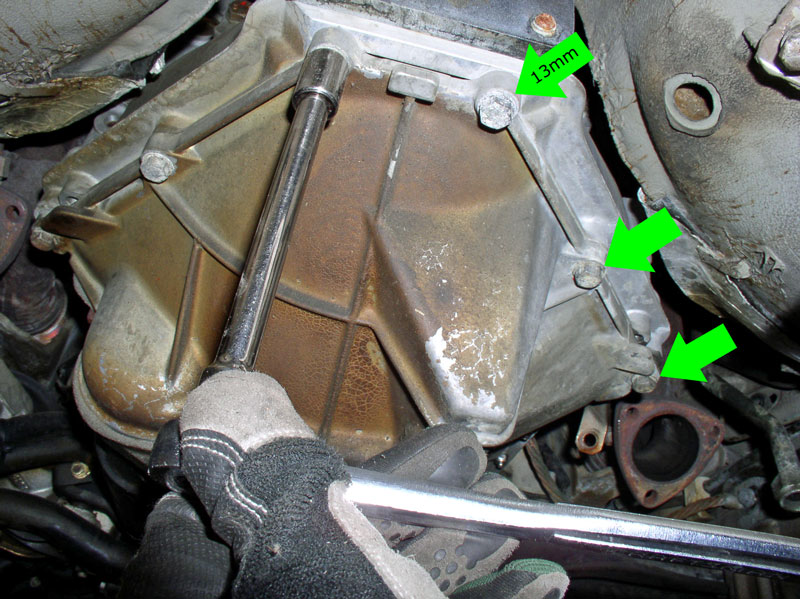
Remove the cover.

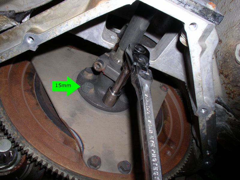
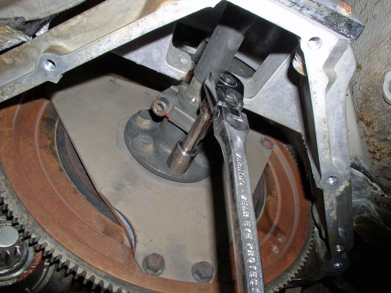
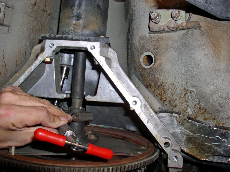
Normally, to relive pre-tension, you would loosen the 8mm Allen head pinch bolt on the drive shaft clamp. However, I left that in tact since I needed to stay secure later on when I pry the drive shaft from the TT. Instead, I loosened the 6 bolts that secure the drive shaft clamp flange to the flex plate as shown in the picture. Loosen only enough to relieve the tension. These are 15mm.
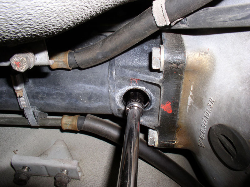
Remove the protective inspection hole cover at the rear end of the TT.
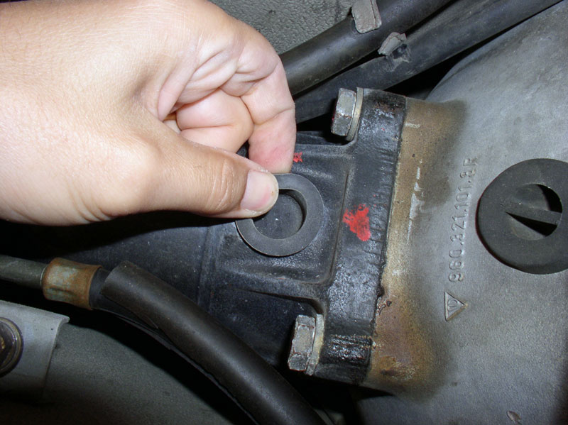
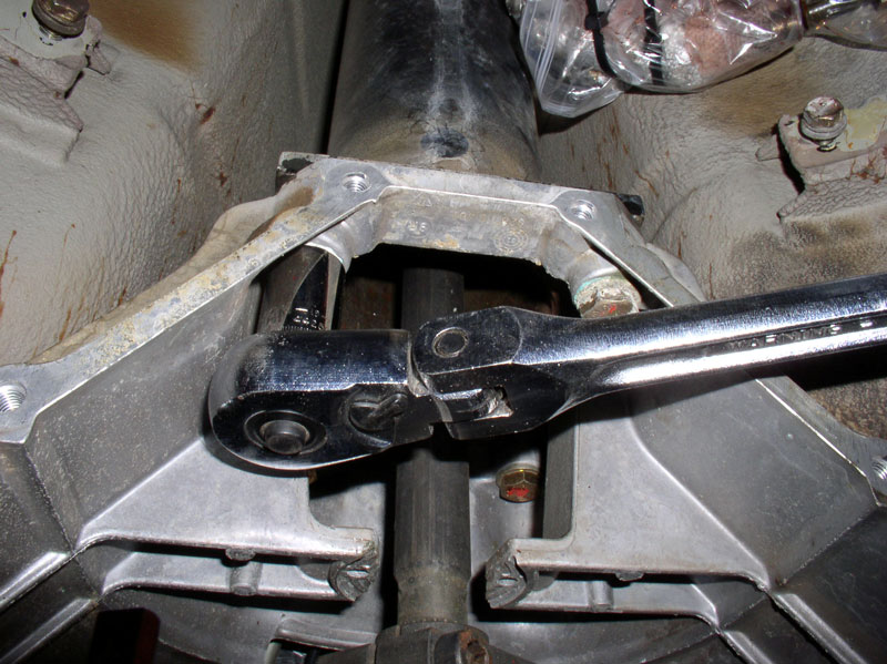
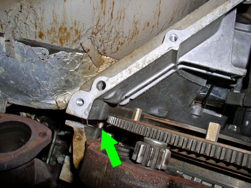
Rotate the engine CLOCKWISE until the head of the drive shaft clamp pinch bolt is visible and accessible with a socket as shown.
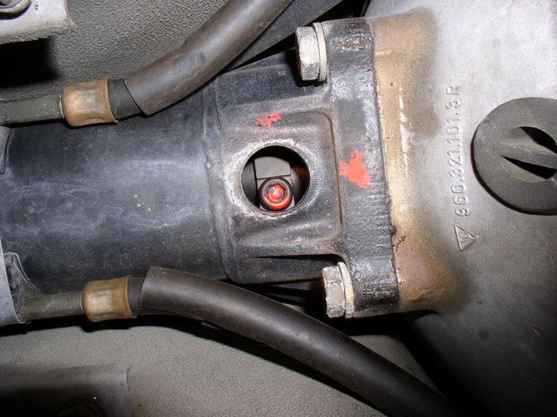
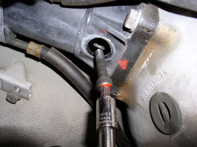
Using an 8mm Allen head socket and extension, I loosened the pinch bolt making sure the socket is well seated in the Allen head bolt.
I went ahead and removed the bolt completely.
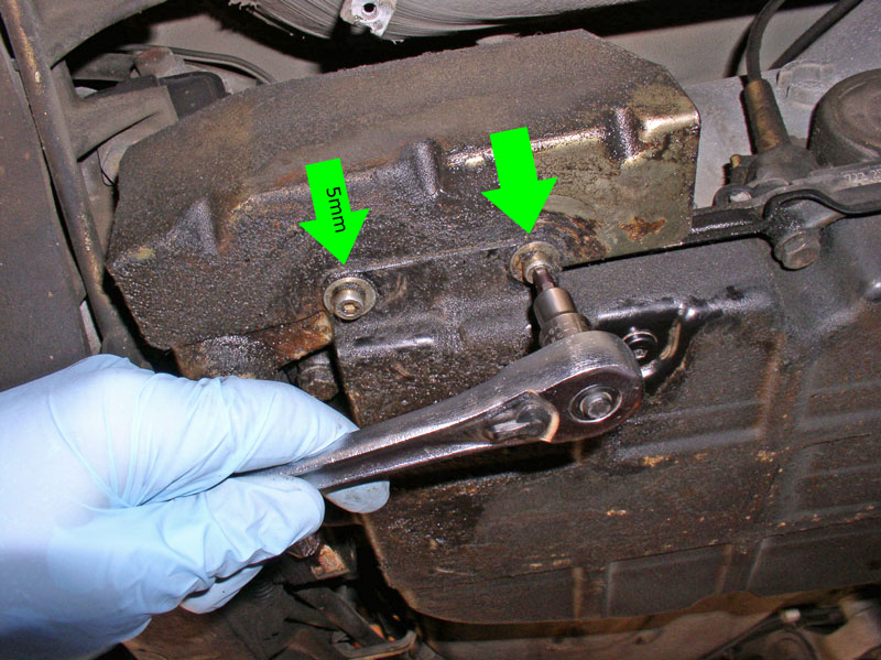
I also found it easier to remove the rear suspension (clearance wise) if the transmission fluid reservoir were removed. Start by removing the 2 bolts that secure the reservoir to the fluid pan. They are 5mm Allen head bolts.
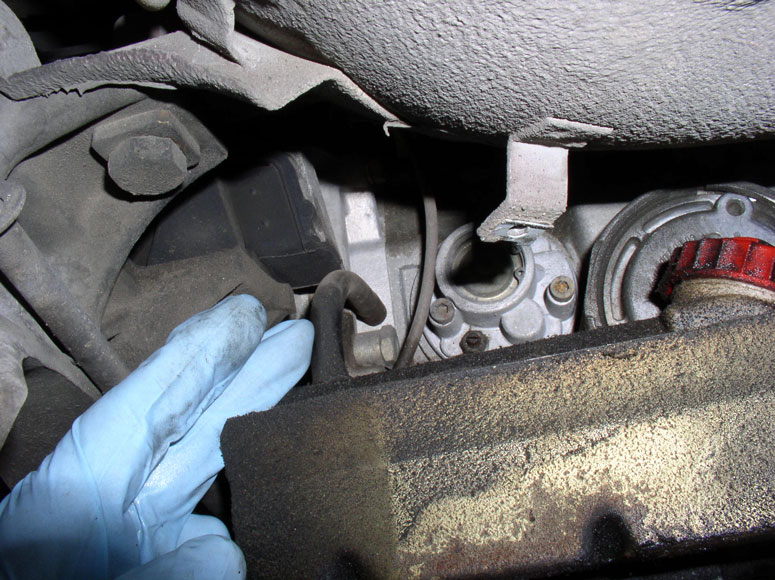
Disconnect the rubber hose at the top of the reservoir. Even though I disconnected the hose at the reservoir, it would be preferable to disconnect the hose at the transmission because the plastic mount for the hose on the reservoir may be brittle and break. The connection on the transmission is metal and a better option (THANKS to Stan (Mrmerlin) for the tip!).
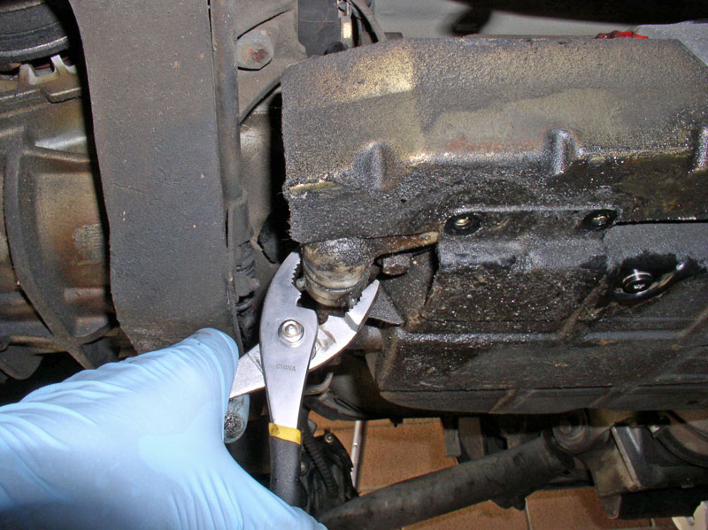
Next, I used a pair of pliers to loosen and remove the plastic nut on the pan filler tube. Position the same drain pan used earlier underneath the reservoir to catch any additional fluid that will come out.
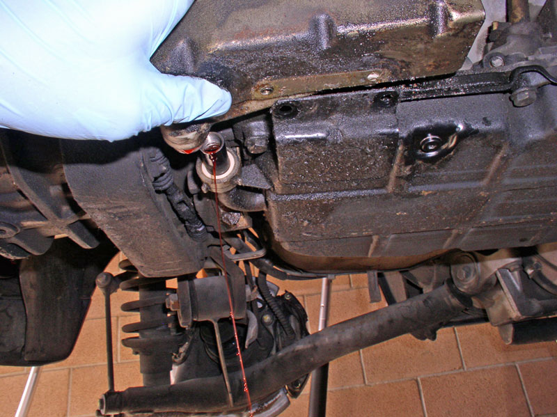
Remove the reservoir by turning and pulling the reservoir outward.
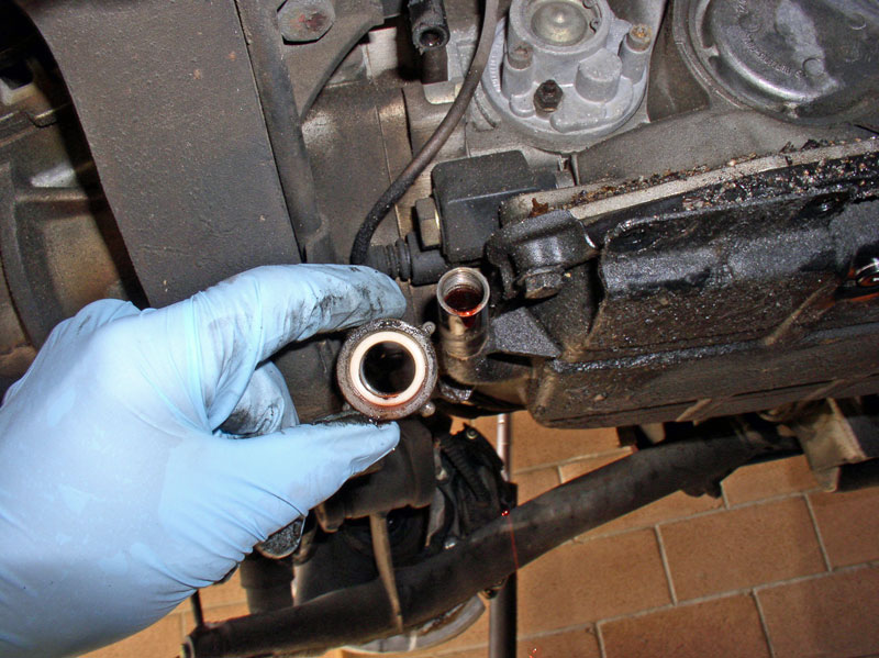
With the reservoir removed, you can pull the plastic nut off the filler tube and you should be able to see/inspect the O-Ring seal. I recommend replacing this ring while you have the reservoir off. It is available from most of our 928 parts vendors.
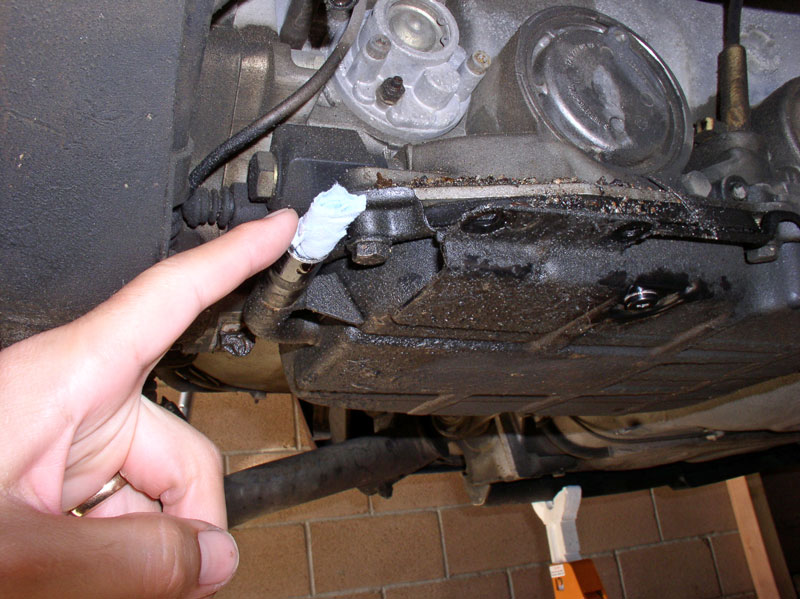
After the fluid had dripped out of the filler tube, I stuffed a paper towel in the filler tube to prevent dirt contamination and additional fluid leaking. Later on, I decided to simply put a rubber vacuum plug on the filler tube and it worked much better.
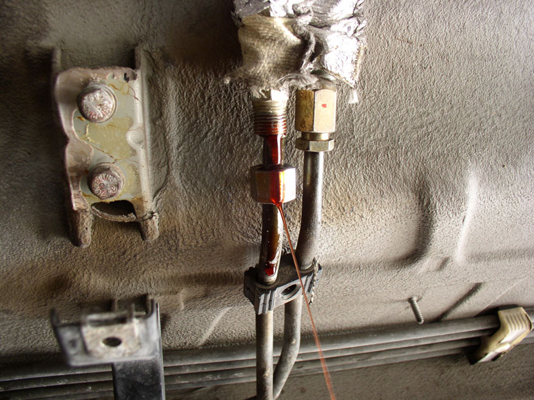
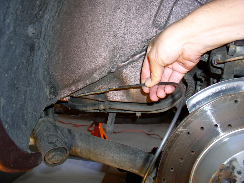
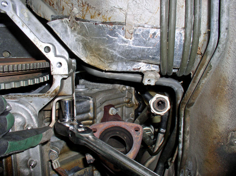
One last item to take care of before removing the rear suspension was disconnecting the transmission fluid cooler lines. Pictured here, they are wrapped in a heat reflective fire resistant material.
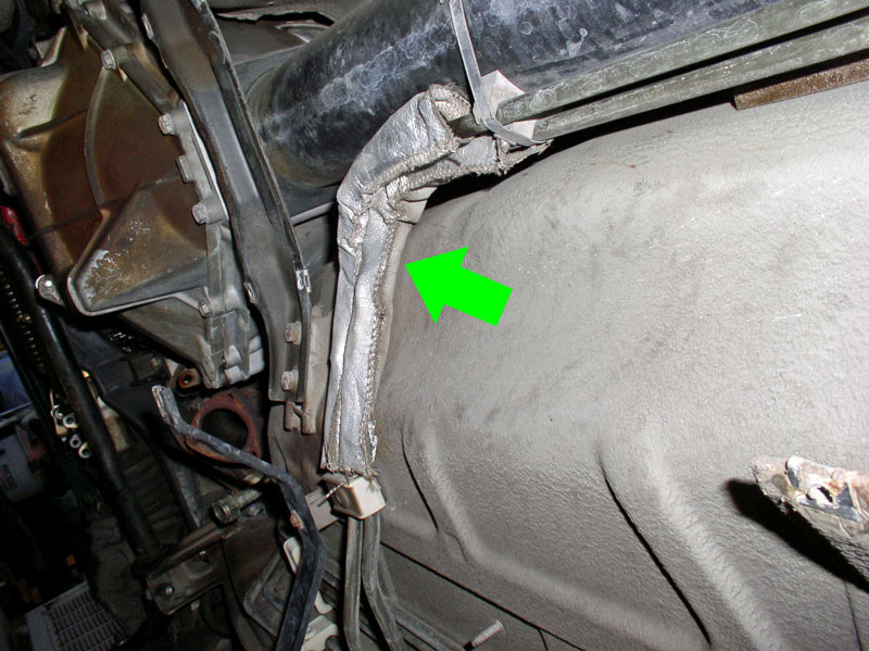
First, remove the plastic 5mm screw securing the lines to the underbody.
Continued....
Removing the rear suspension includes removing the rear cross brace which provides safety and stability while working under the transmission and TT. There are a few things to do before removing the cross brace. The first is to loosen and remove the rear drive line clamp pinch bolt. This is required to separate the TT from the TC housing later on and it will be much easier to remove it now while you can easily get under the TT. It is best to relieve any pre-tension on the flexplate first as this may cause the pinch bolt to stick when trying to remove it. First, remove the 6 bolts that hold the front, lower bell housing cover in place. They are 13mm.
Remove the cover.
Normally, to relive pre-tension, you would loosen the 8mm Allen head pinch bolt on the drive shaft clamp. However, I left that in tact since I needed to stay secure later on when I pry the drive shaft from the TT. Instead, I loosened the 6 bolts that secure the drive shaft clamp flange to the flex plate as shown in the picture. Loosen only enough to relieve the tension. These are 15mm.
Remove the protective inspection hole cover at the rear end of the TT.
Rotate the engine CLOCKWISE until the head of the drive shaft clamp pinch bolt is visible and accessible with a socket as shown.
Using an 8mm Allen head socket and extension, I loosened the pinch bolt making sure the socket is well seated in the Allen head bolt.
I went ahead and removed the bolt completely.
I also found it easier to remove the rear suspension (clearance wise) if the transmission fluid reservoir were removed. Start by removing the 2 bolts that secure the reservoir to the fluid pan. They are 5mm Allen head bolts.
Disconnect the rubber hose at the top of the reservoir. Even though I disconnected the hose at the reservoir, it would be preferable to disconnect the hose at the transmission because the plastic mount for the hose on the reservoir may be brittle and break. The connection on the transmission is metal and a better option (THANKS to Stan (Mrmerlin) for the tip!).
Next, I used a pair of pliers to loosen and remove the plastic nut on the pan filler tube. Position the same drain pan used earlier underneath the reservoir to catch any additional fluid that will come out.
Remove the reservoir by turning and pulling the reservoir outward.
With the reservoir removed, you can pull the plastic nut off the filler tube and you should be able to see/inspect the O-Ring seal. I recommend replacing this ring while you have the reservoir off. It is available from most of our 928 parts vendors.
After the fluid had dripped out of the filler tube, I stuffed a paper towel in the filler tube to prevent dirt contamination and additional fluid leaking. Later on, I decided to simply put a rubber vacuum plug on the filler tube and it worked much better.
One last item to take care of before removing the rear suspension was disconnecting the transmission fluid cooler lines. Pictured here, they are wrapped in a heat reflective fire resistant material.
First, remove the plastic 5mm screw securing the lines to the underbody.
Continued....
Last edited by Dwayne; 12-20-2010 at 02:09 PM.
 12-19-2010, 04:53 PM
#17
Rennlist Member
Thread Starter
Join Date: Sep 2007
Location: Ridgecrest, California
Posts: 1,363
Likes: 0
Received 143 Likes
on
28 Posts
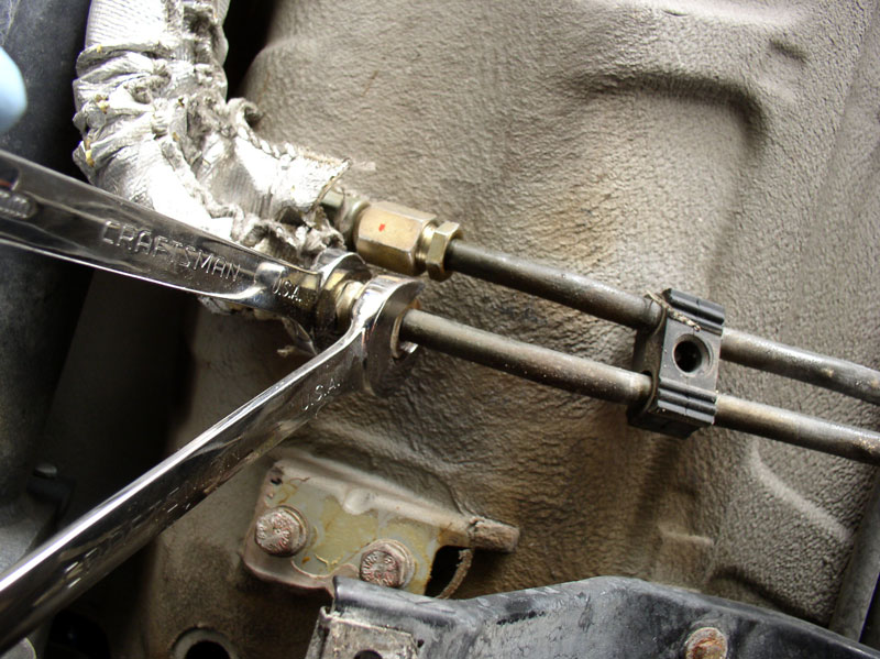
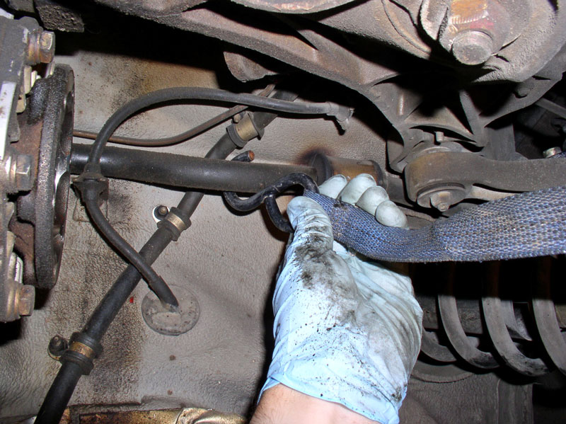
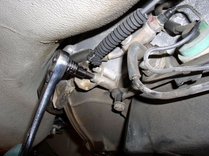
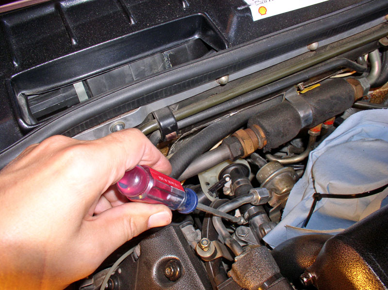
Push back the heat protective sleeves as shown so you can access the connectors. Position the same drain pan used earlier underneath the hose connectors to catch any additional fluid that will come out.
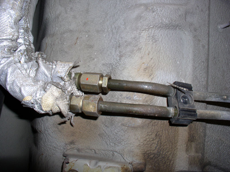
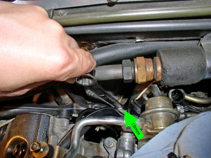
Using 19mm and 17mm wrenches to counter-hold the connector, loosen and disconnect both hoses from the hard line.
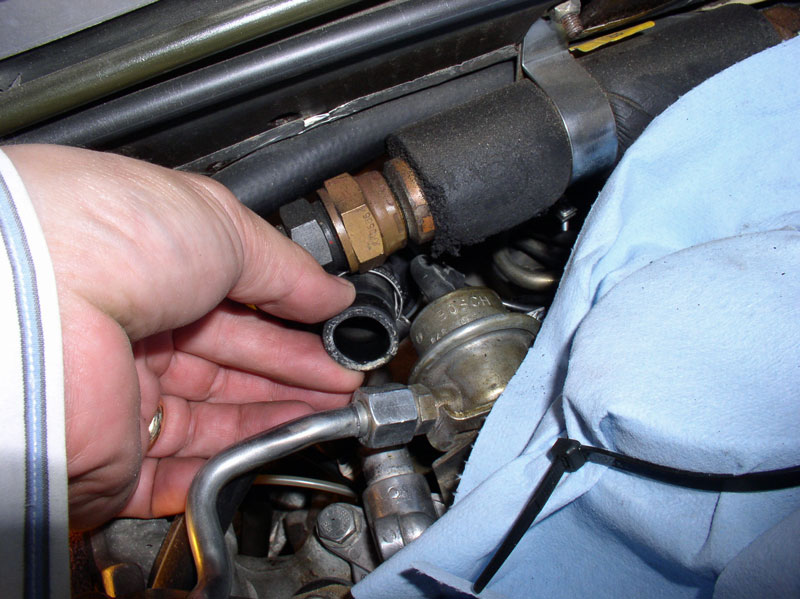
Let residual fluid drain from the hoses. You will also notice the hard line and hose connections are mated opposite so there is only one way they can be connected (i.e., there is no need to mark or identify which hose goes to which hard line).
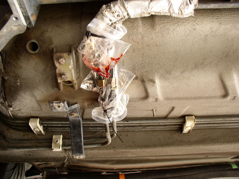
Once the lines have stopped draining, wrap a towel around the ends of the lines and place a plastic baggie over the both ends of the hoses and hard lines. I used zip ties to secure the plastic in place.
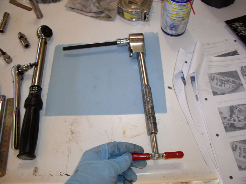
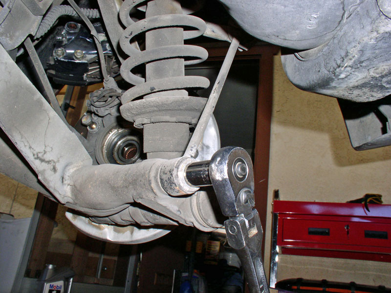
Next, I disconnected the axle half-shafts from the transmission. I found the following tool combination useful. It�s a long Allen socket with a �T� handle ratchet (purchased at HF).
I simply set the parking brake to hold the axle shaft in place while loosening the Allen head bolts. Once the parking brake is set, I was able to access 3 bolts at a time for each axle shaft (the 3 rearward facing bolts). Ensure the Allen socket is firmly, fully seated in the bolt head to minimize risk of striping the head. I used the ratchet first to break the bolts loose then used the �T� handle to quickly remove the bolt so it cleared the differential case. Leave the bolts attached to the CV joint. These are 8mm Allen head bolts.
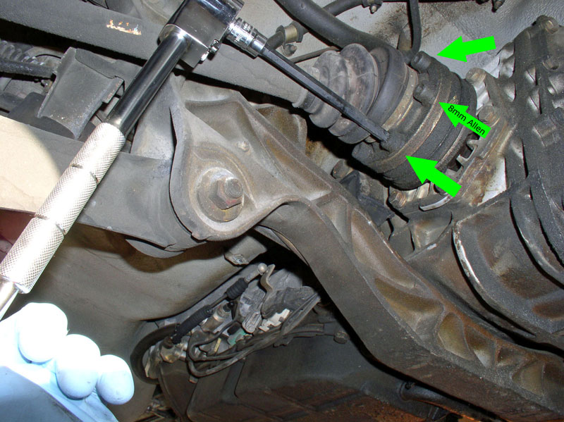
After I loosened 3 Allen head bolts on each side, I released the parking brake and rotated the axle (by turning the hub) 180 degrees to line up the remaining 3 bolts. I reset the parking brake and loosened the remaining bolts.
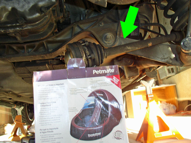
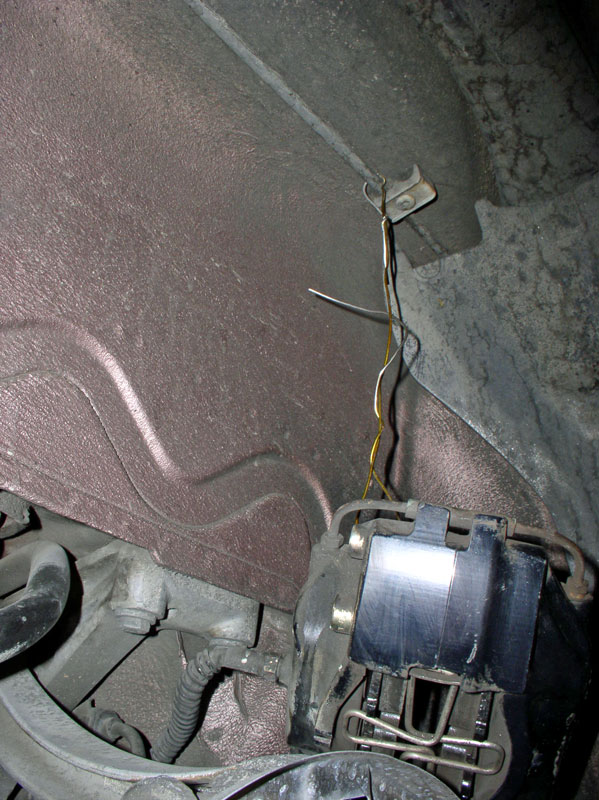
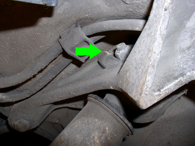
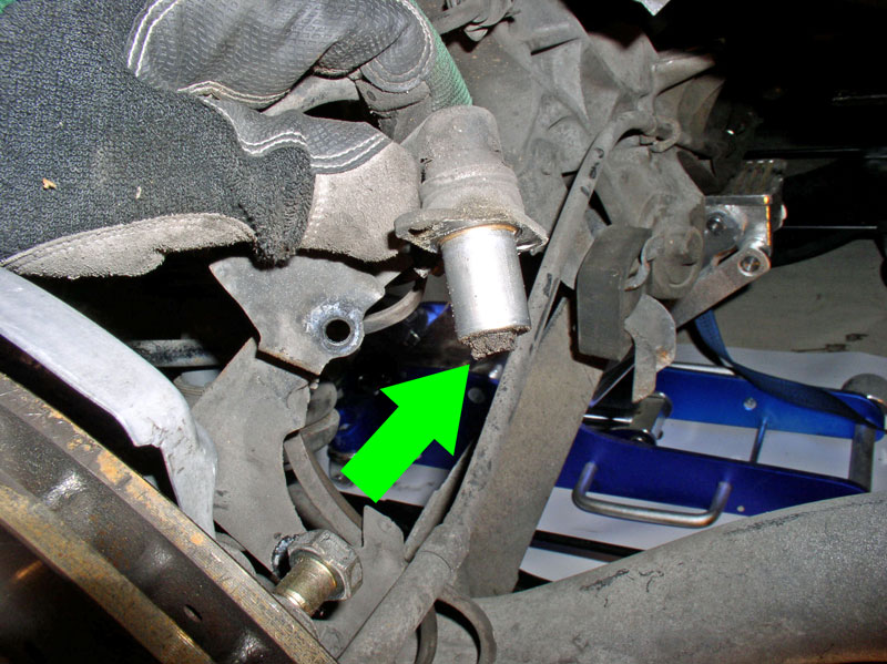
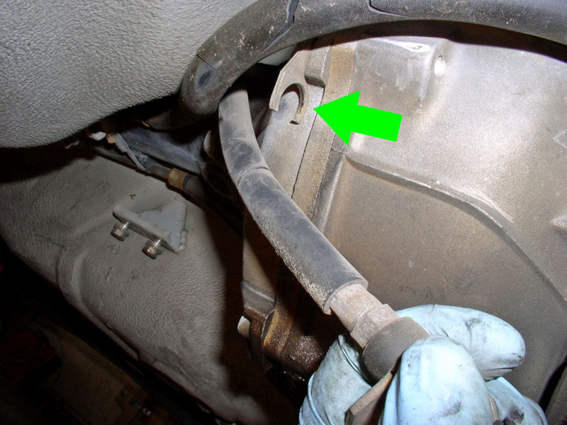
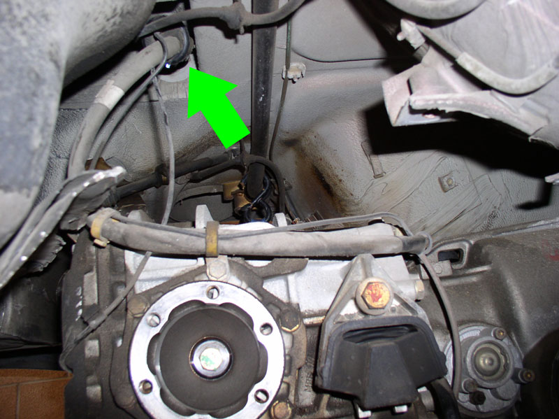
Have a box handy to hold the axle half shaft aloft while it is either removed (if you�re also doing CV boot repair) or suspended and attached to the cross brace. I have used the brace indicated by the green arrow in the picture below to attach some wire and secure the axle shaft to the cross member.
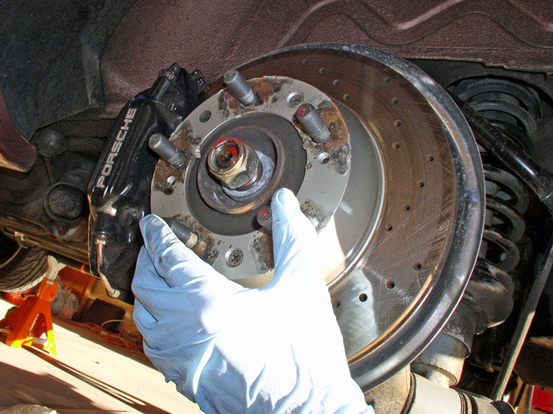
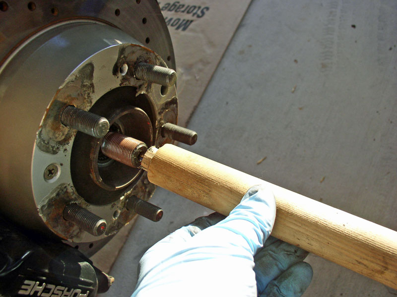
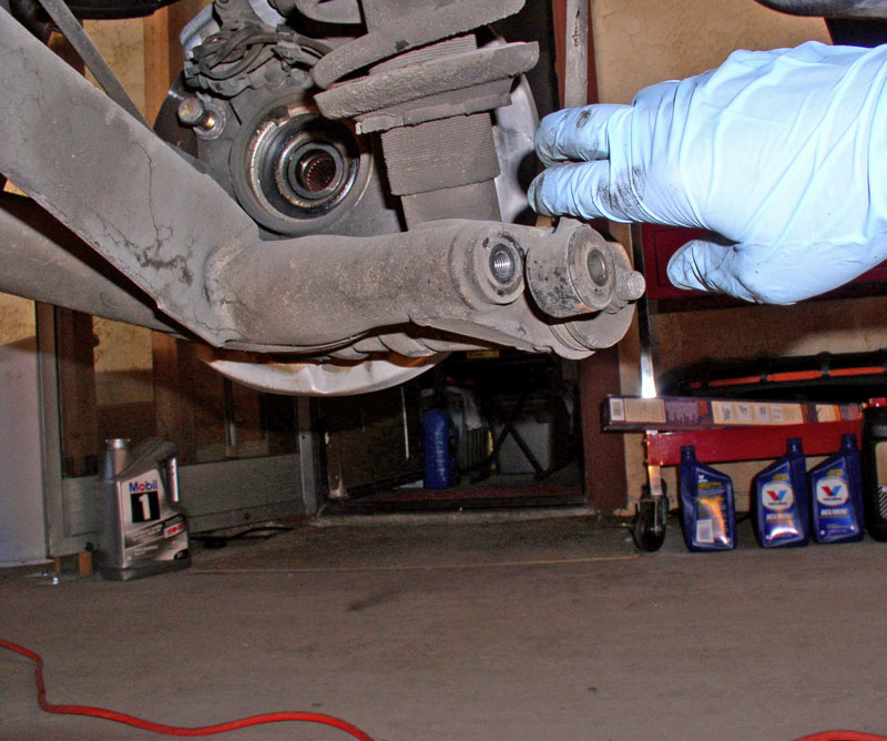
[CV Boot repair prep step] Since I was needing to remove the axle half shaft to repair the CV boots, I then removed the axle nut and pulled the axle shaft out of the rear wheel hub. If the axle shaft won�t come out of the hub with a gentle tug, I tap it out using a wooden dowel I made from a wooden clothes hanger rod.
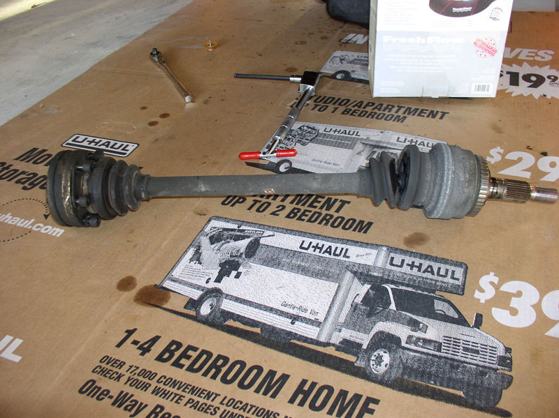
[CV Boot repair prep step] Once removed, I set the axle shaft aside to work later. This step is not required if you are not repairing the CV Boots.
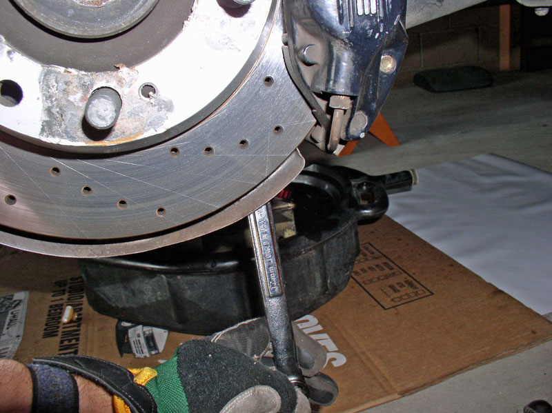
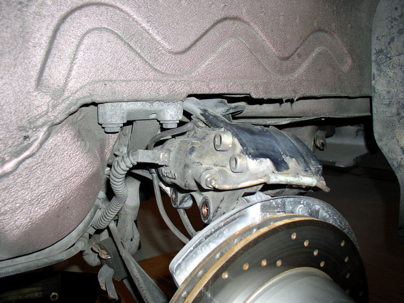
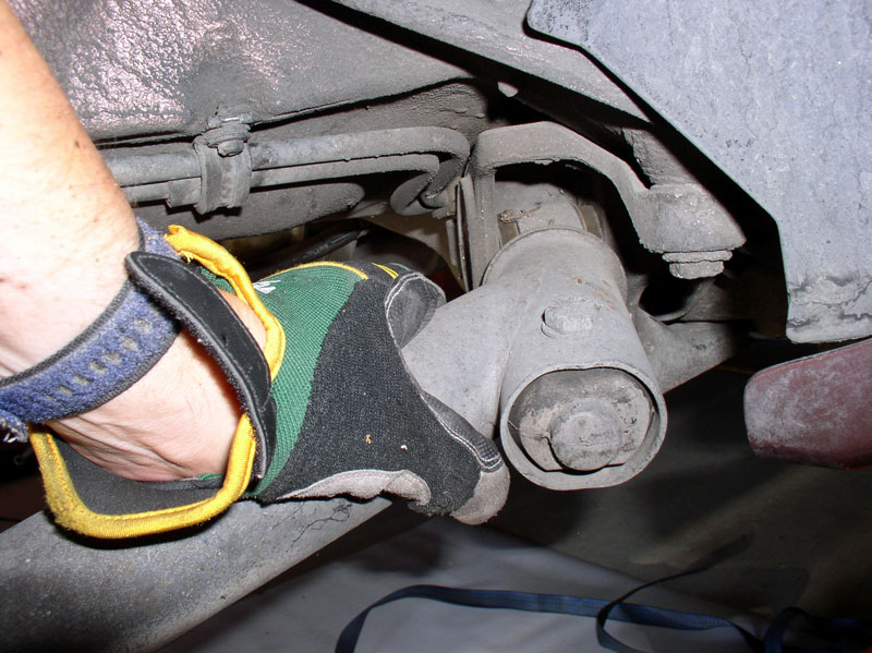
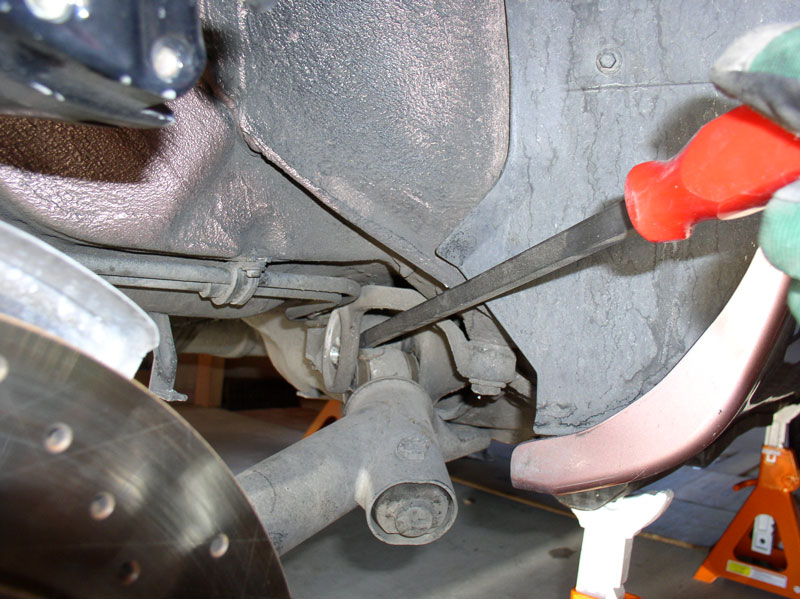
I removed the brake calipers next. The caliper is secured to the hub carrier using two 19mm bolts. I use a long handle ratchet to provide extra leverage to break the upper bolt loose.
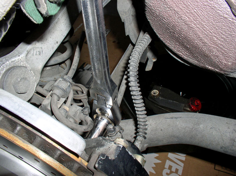
There�s not as much clearance to use the same ratchet/socket on the lower bolt. For these, I use an extended closed end wrench to break the bolt loose. Then you can switch to a shorter, ratcheting wrench to remove the bolt the rest of the way.
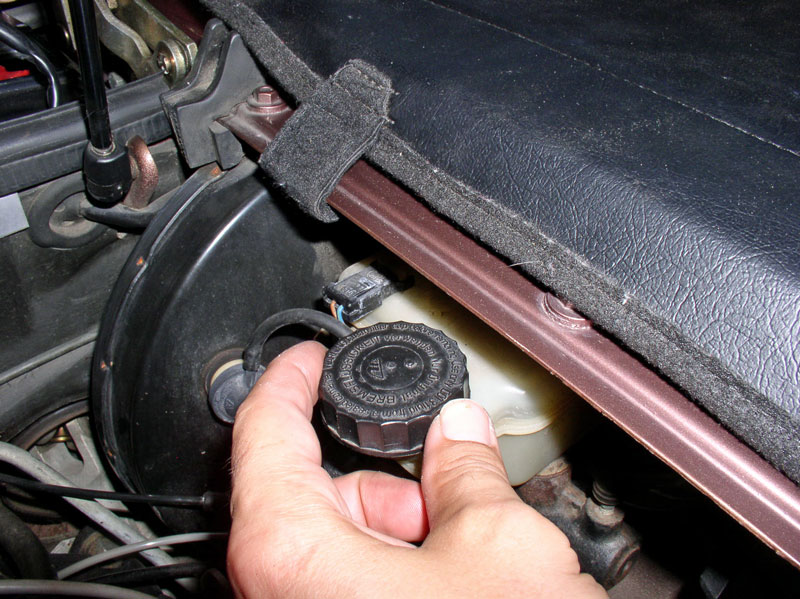
If the rotors are worn enough that there is a lip on the outer edge, you may have to push the brake pads/cylinders back into the caliper in order to create enough clearance to remove the caliper. If this is required, remember to loosen the cap to the brake fluid reservoir so the brake fluid can freely �back up� when pressing the brake pads in.
Remove the brake caliper from the hub carrier.
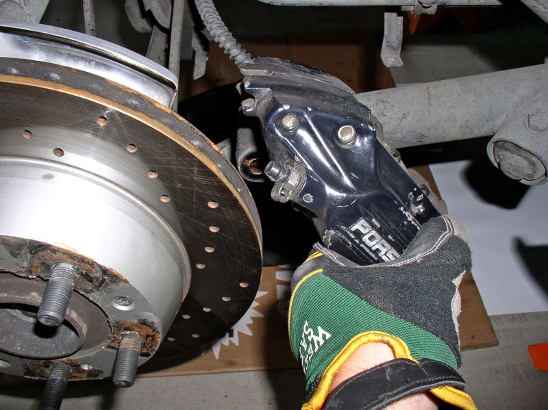
For the right hand side caliper, I suspended the caliper from the hard line pictured below using wire.
Continued....
Using 19mm and 17mm wrenches to counter-hold the connector, loosen and disconnect both hoses from the hard line.
Let residual fluid drain from the hoses. You will also notice the hard line and hose connections are mated opposite so there is only one way they can be connected (i.e., there is no need to mark or identify which hose goes to which hard line).
Once the lines have stopped draining, wrap a towel around the ends of the lines and place a plastic baggie over the both ends of the hoses and hard lines. I used zip ties to secure the plastic in place.
Next, I disconnected the axle half-shafts from the transmission. I found the following tool combination useful. It�s a long Allen socket with a �T� handle ratchet (purchased at HF).
I simply set the parking brake to hold the axle shaft in place while loosening the Allen head bolts. Once the parking brake is set, I was able to access 3 bolts at a time for each axle shaft (the 3 rearward facing bolts). Ensure the Allen socket is firmly, fully seated in the bolt head to minimize risk of striping the head. I used the ratchet first to break the bolts loose then used the �T� handle to quickly remove the bolt so it cleared the differential case. Leave the bolts attached to the CV joint. These are 8mm Allen head bolts.
After I loosened 3 Allen head bolts on each side, I released the parking brake and rotated the axle (by turning the hub) 180 degrees to line up the remaining 3 bolts. I reset the parking brake and loosened the remaining bolts.
Have a box handy to hold the axle half shaft aloft while it is either removed (if you�re also doing CV boot repair) or suspended and attached to the cross brace. I have used the brace indicated by the green arrow in the picture below to attach some wire and secure the axle shaft to the cross member.
[CV Boot repair prep step] Since I was needing to remove the axle half shaft to repair the CV boots, I then removed the axle nut and pulled the axle shaft out of the rear wheel hub. If the axle shaft won�t come out of the hub with a gentle tug, I tap it out using a wooden dowel I made from a wooden clothes hanger rod.
[CV Boot repair prep step] Once removed, I set the axle shaft aside to work later. This step is not required if you are not repairing the CV Boots.
I removed the brake calipers next. The caliper is secured to the hub carrier using two 19mm bolts. I use a long handle ratchet to provide extra leverage to break the upper bolt loose.
There�s not as much clearance to use the same ratchet/socket on the lower bolt. For these, I use an extended closed end wrench to break the bolt loose. Then you can switch to a shorter, ratcheting wrench to remove the bolt the rest of the way.
If the rotors are worn enough that there is a lip on the outer edge, you may have to push the brake pads/cylinders back into the caliper in order to create enough clearance to remove the caliper. If this is required, remember to loosen the cap to the brake fluid reservoir so the brake fluid can freely �back up� when pressing the brake pads in.
Remove the brake caliper from the hub carrier.
For the right hand side caliper, I suspended the caliper from the hard line pictured below using wire.
Continued....
12-19-2010, 05:05 PM
#18
Rennlist Member
Thread Starter
Join Date: Sep 2007
Location: Ridgecrest, California
Posts: 1,363
Likes: 0
Received 143 Likes
on
28 Posts
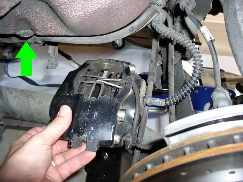
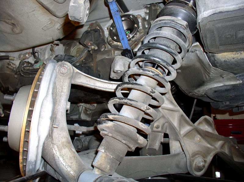
There isn�t a convenient place to suspend the left side caliper until the suspension is lowered. For now, I simply let it rest atop the upper control arm as shown. Later on it will be suspended more securely.
Next, the emergency brake cable needed to be disconnected and removed from the interior. Behind the driver�s seat, remove the 3 Phillips head screws as depicted in the picture that secure the e-brake cable cover.
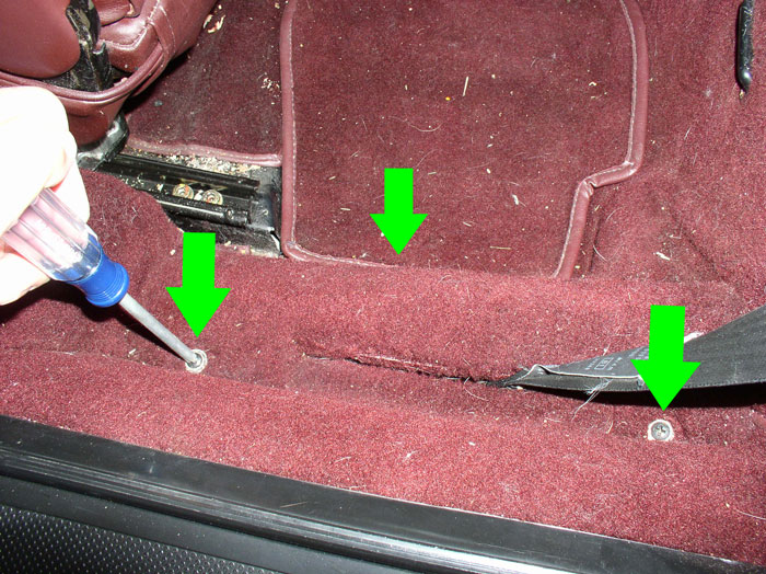
Remove the cover.
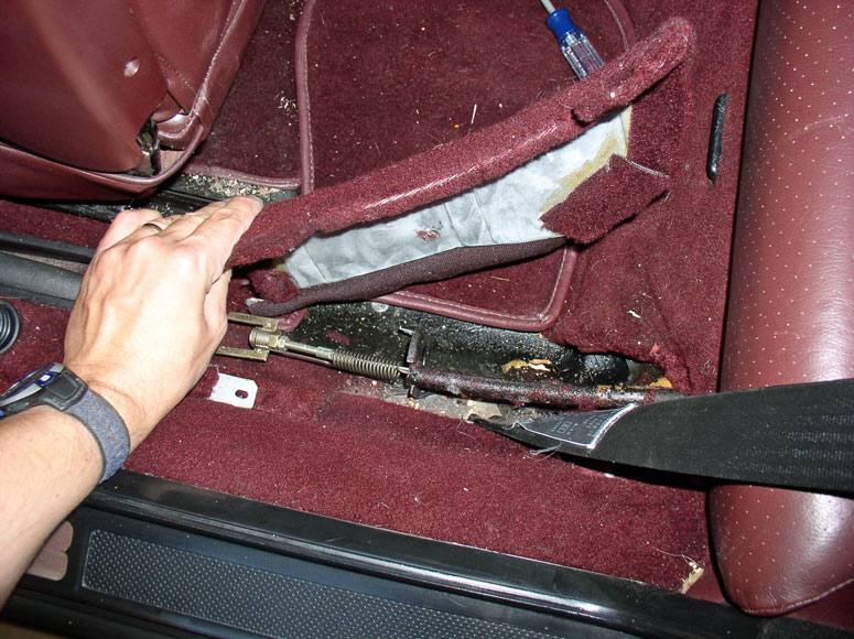
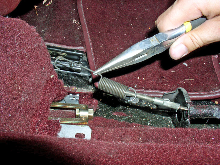
Disconnect the spring from the cable linkage as shown.
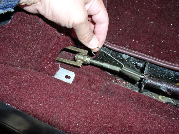
Using a 14mm wrench to hold the adjusting nut, use a 10mm wrench to loosen the small locknut as shown.
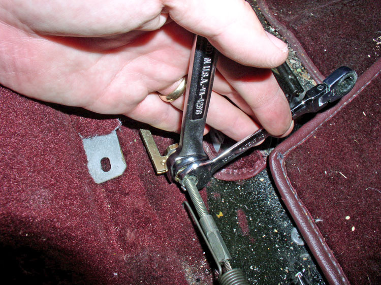
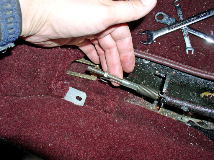
Once the locknut is loosened, you should be able to turn the adjusting nut until the cable is disconnected from the cable linkage.
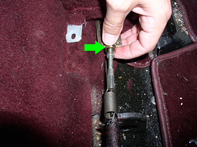
Once the cable is disconnected, remove the 10mm locking nut from the cable�..
�.and detach the spring and remove it from the cable as well.
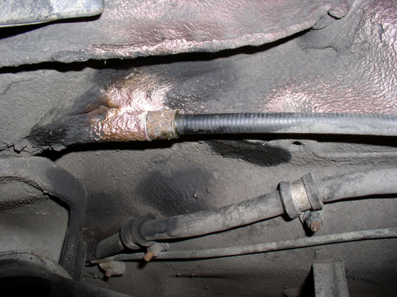
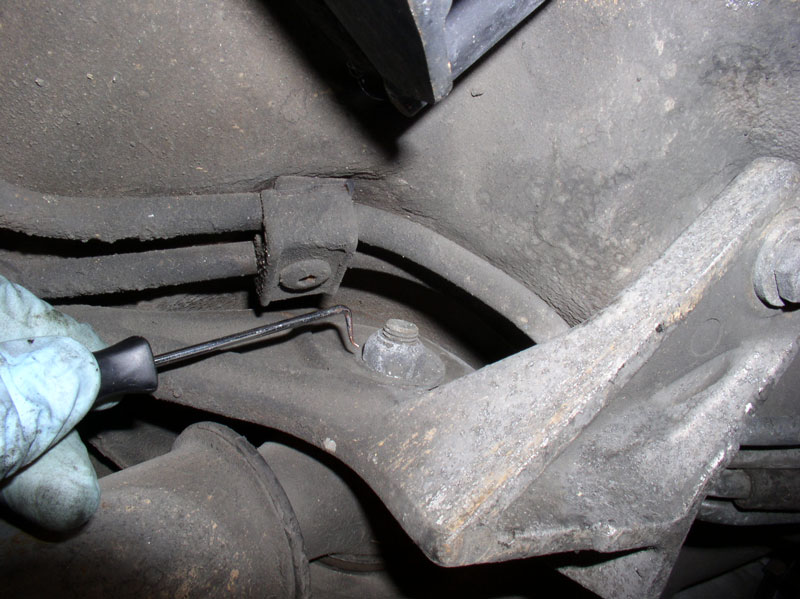
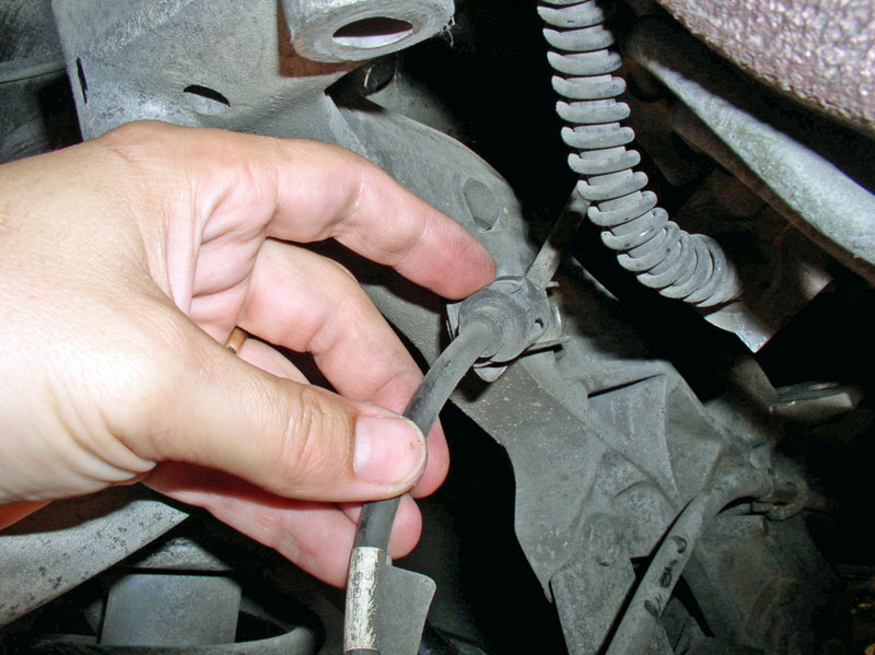
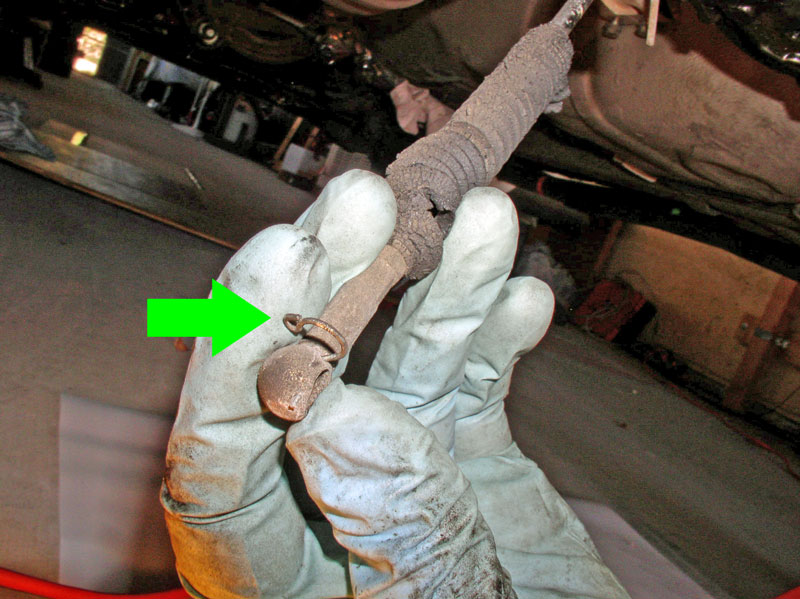
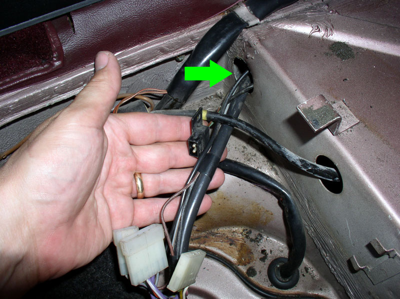
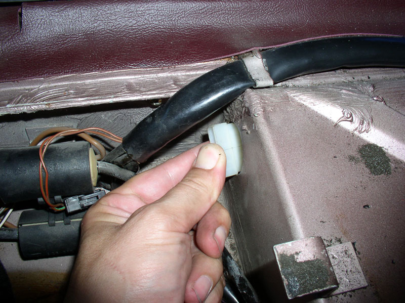
Follow the e-brake cable to find where it enters the floorboard. I cleaned the area to determine what type of fitting is used here. It turns out it�s just pressed in. However, mine was not about to come out freely and needed a little help.
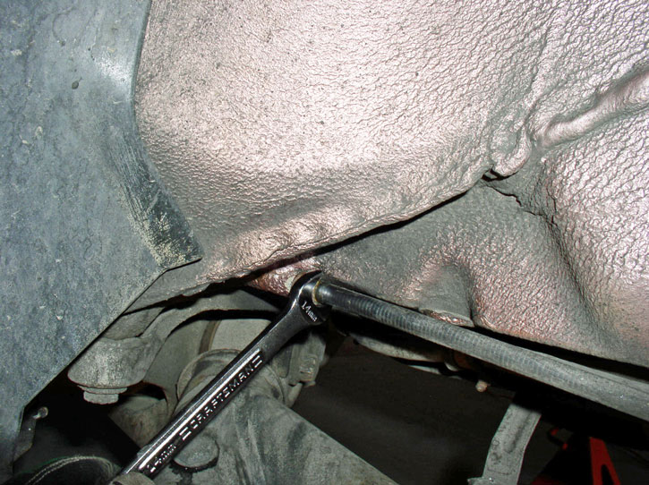
I used a 14mm wrench to break the cable free by rotating the wrench up and down while pulling the cable rearward. It slowly worked free.
Upon closer inspection, the cable fitting has an o-ring used to provide a water tight seal so water does not enter into the cabin.
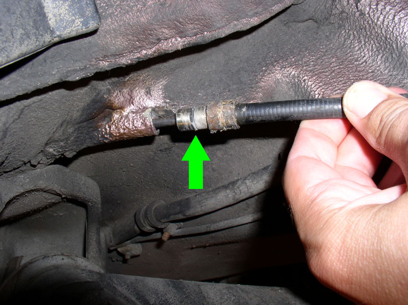
Pull the rest of the cable from the floorboard as shown.
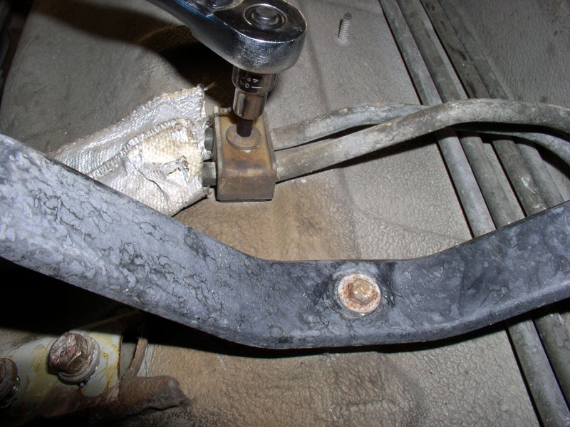
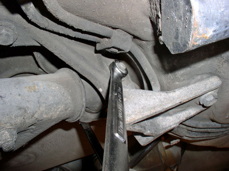
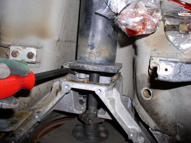
Next, I loosened and removed the 17mm bolt holding the rear drop links to the lower control arm.
The bolt will be under tension so it may require a little down force on the drop link to pull the bolt out. To make it easier to maneuver the rear suspension down and out from under the car, the drop link can be detached from the sway bar above and the link removed completely. If you do remove the drop links, remember to mark them as to which side they came from as they are different. I left mine attached � because I�m a Newb!
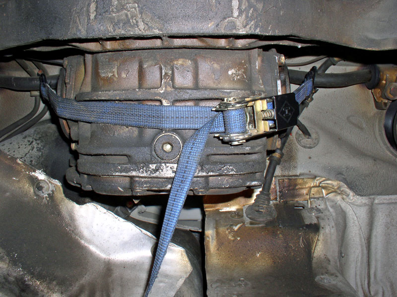
Next, I prepared to suspend the transmission and TT before removing the last bolts securing the rear suspension. I used a ratcheting tie down strap. Make sure it is rated for heavy duty such as 800+ lbs. You can also use a chain. I affixed one end of the strap to the sway bar as shown in the picture and the other end to the sway bar on the other side of the differential.
Continued....
Next, the emergency brake cable needed to be disconnected and removed from the interior. Behind the driver�s seat, remove the 3 Phillips head screws as depicted in the picture that secure the e-brake cable cover.
Remove the cover.
Disconnect the spring from the cable linkage as shown.
Using a 14mm wrench to hold the adjusting nut, use a 10mm wrench to loosen the small locknut as shown.
Once the locknut is loosened, you should be able to turn the adjusting nut until the cable is disconnected from the cable linkage.
Once the cable is disconnected, remove the 10mm locking nut from the cable�..
�.and detach the spring and remove it from the cable as well.
Follow the e-brake cable to find where it enters the floorboard. I cleaned the area to determine what type of fitting is used here. It turns out it�s just pressed in. However, mine was not about to come out freely and needed a little help.
I used a 14mm wrench to break the cable free by rotating the wrench up and down while pulling the cable rearward. It slowly worked free.
Upon closer inspection, the cable fitting has an o-ring used to provide a water tight seal so water does not enter into the cabin.
Pull the rest of the cable from the floorboard as shown.
Next, I loosened and removed the 17mm bolt holding the rear drop links to the lower control arm.
The bolt will be under tension so it may require a little down force on the drop link to pull the bolt out. To make it easier to maneuver the rear suspension down and out from under the car, the drop link can be detached from the sway bar above and the link removed completely. If you do remove the drop links, remember to mark them as to which side they came from as they are different. I left mine attached � because I�m a Newb!
Next, I prepared to suspend the transmission and TT before removing the last bolts securing the rear suspension. I used a ratcheting tie down strap. Make sure it is rated for heavy duty such as 800+ lbs. You can also use a chain. I affixed one end of the strap to the sway bar as shown in the picture and the other end to the sway bar on the other side of the differential.
Continued....
12-19-2010, 05:25 PM
#19
Rennlist Member
Thread Starter
Join Date: Sep 2007
Location: Ridgecrest, California
Posts: 1,363
Likes: 0
Received 143 Likes
on
28 Posts
I ratcheted the strap down until I could see the differential move slightly upward indicating the weight of the transmission being supported by the strap. I located the strap just rearward of the larger casting ridge in the differential case as shown. This kept the strap clear of the rear suspension cross member for removal.
Next, I marked (scribed) the location of the lower control arm eccentrics.
Make sure the mark remains visible on the eccentric and body as shown. I marked both front and rear of the eccentrics for both wheels.
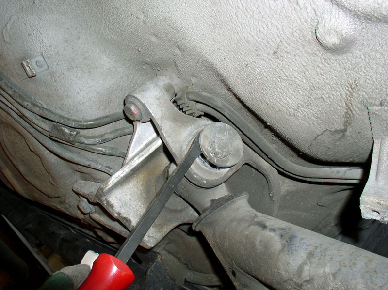
Next, I loosened and removed the eccentric bolt. You will need to loosen and remove the nut that faces the front. There�s not a lot of room to work so I used an extended length closed end 19mm wrench for additional leverage to break the nut free while counter holding the rearward facing bolt (also 19mm).
Once the nut was removed, I used a short pry bar to lever the eccentric bolt out of the carrier as shown.
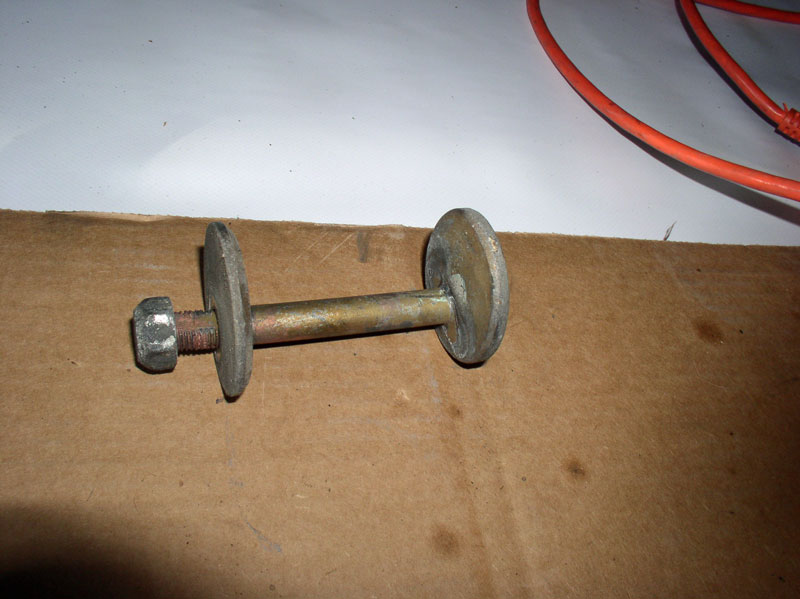
Once the bolt is removed, I assembled the nut and washer in the original configuration and set it aside. I then removed the eccentric bolt from the opposite wheel lower control arm.
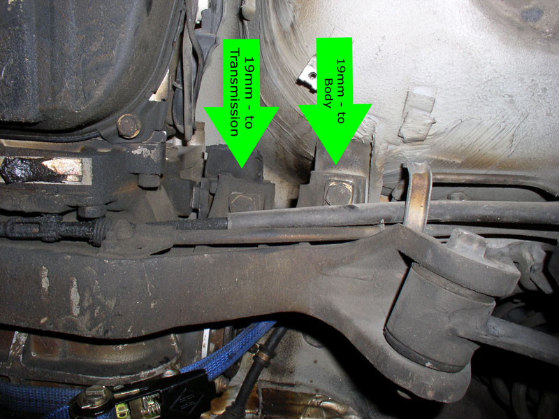
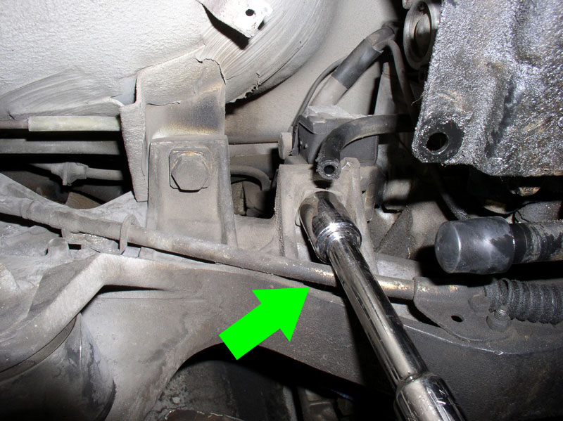
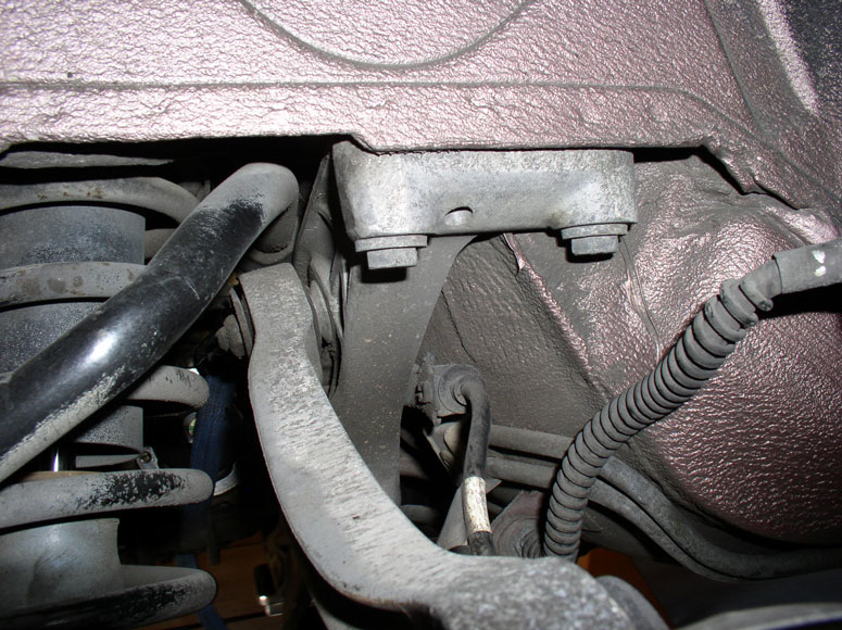
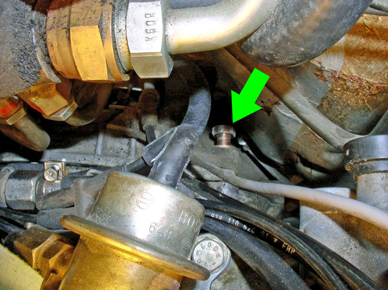
I then removed the bolts that secure the cross member to the body and secure the transmission mounts to the cross member. These are both 19mm bolts with a square washer. The outer bolt secures the cross member to the body while the inner secures the transmission mount to the cross member.
I removed these bolts using the 19mm socket and 6� extension bar along with a long handled �� ratchet for additional leverage. You can see from the picture I maneuvered the socket between the e-brake cable. I�ve also found it easier to just lift up the e-brake cable and remove it from it�s hanger shown just to the left of the green arrow below.
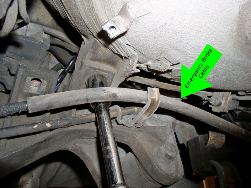
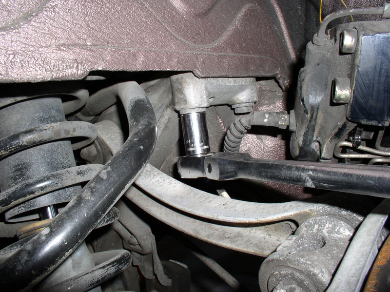
For the passenger side bolts, the hard line e-brake cable makes it a tight fit but it is possible to maneuver the socket and extension in such a way to get access as shown. At this time, you can see I located and installed a rubber vacuum plug for the transmission filler tube and used it instead of the paper towel � much better.
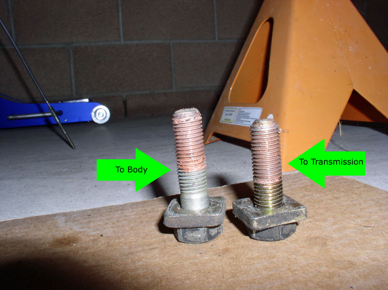
When the 19mm bolts are removed, you will notice one is shorter than the other. The shorter of the two secures the transmission to the cross member and the longer secures the cross member to the body.
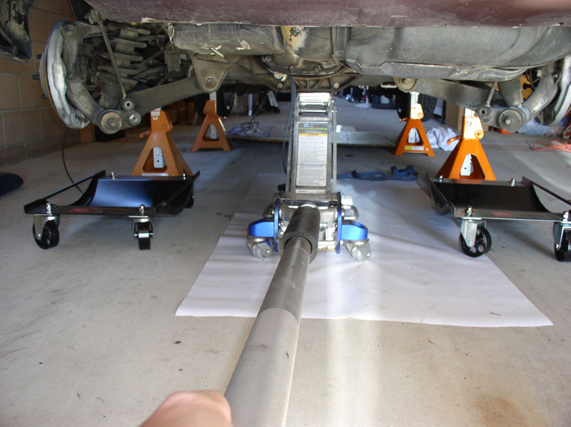
Next, I positioned the car dolly (or suitable alternative) under the rear wheel lower control arm assemblies for both wheels.
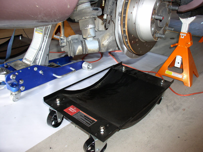
I positioned the floor jack under the center of the cross member and applied enough support to take the weight off the remaining cross member bolts.
These are the last remaining bolts securing the cross member to the body. They are two 17mm bolts on each side.
Before removing the bolts, it�s a good idea to mark the location of the cross member to the body with a scribe or marker or paint. This will guide you to get the rear suspension close to the original installed location. However, I still needed an alignment afterward.
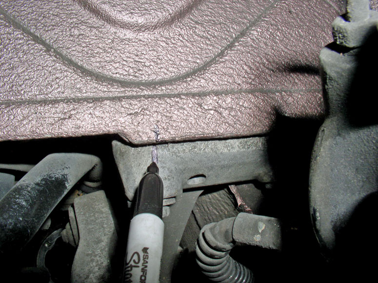
Next, remove the four 17mm bolts (2 each side of the car).
Continued....
Next, I marked (scribed) the location of the lower control arm eccentrics.
Make sure the mark remains visible on the eccentric and body as shown. I marked both front and rear of the eccentrics for both wheels.
Next, I loosened and removed the eccentric bolt. You will need to loosen and remove the nut that faces the front. There�s not a lot of room to work so I used an extended length closed end 19mm wrench for additional leverage to break the nut free while counter holding the rearward facing bolt (also 19mm).
Once the nut was removed, I used a short pry bar to lever the eccentric bolt out of the carrier as shown.
Once the bolt is removed, I assembled the nut and washer in the original configuration and set it aside. I then removed the eccentric bolt from the opposite wheel lower control arm.
I then removed the bolts that secure the cross member to the body and secure the transmission mounts to the cross member. These are both 19mm bolts with a square washer. The outer bolt secures the cross member to the body while the inner secures the transmission mount to the cross member.
I removed these bolts using the 19mm socket and 6� extension bar along with a long handled �� ratchet for additional leverage. You can see from the picture I maneuvered the socket between the e-brake cable. I�ve also found it easier to just lift up the e-brake cable and remove it from it�s hanger shown just to the left of the green arrow below.
For the passenger side bolts, the hard line e-brake cable makes it a tight fit but it is possible to maneuver the socket and extension in such a way to get access as shown. At this time, you can see I located and installed a rubber vacuum plug for the transmission filler tube and used it instead of the paper towel � much better.
When the 19mm bolts are removed, you will notice one is shorter than the other. The shorter of the two secures the transmission to the cross member and the longer secures the cross member to the body.
Next, I positioned the car dolly (or suitable alternative) under the rear wheel lower control arm assemblies for both wheels.
I positioned the floor jack under the center of the cross member and applied enough support to take the weight off the remaining cross member bolts.
These are the last remaining bolts securing the cross member to the body. They are two 17mm bolts on each side.
Before removing the bolts, it�s a good idea to mark the location of the cross member to the body with a scribe or marker or paint. This will guide you to get the rear suspension close to the original installed location. However, I still needed an alignment afterward.
Next, remove the four 17mm bolts (2 each side of the car).
Continued....
12-19-2010, 05:30 PM
#20
Team Owner
Nice writeup Dwayne and lots of great pictures,
I would add a few things..
First
I would suggest to leave the reservoir on the pan,
More important, dont remove the hose from the tank but rather from the side of the trans.
\ NOTE this is a metal tube instead of the plastic spout on the tank ( the plastic spout snaps off easily requiring a new tank)
From your pictures if you inspect the front cooler lines above the Cats you may see they are damp,
this indicates a need for new flex hoses to be installed,
your rear lines may be dry but i would also suggest to replace the rear flex lines as well.
NOTE car fires due to ATF fires start over the CATS due to leaking front flex lines, the hard lines can be reused.
Take special note of how far up the cooler lines run along the TT
If they are not positioned up far enough then they will contact the heat shield and possibly catch fire from the CAT heat.
And also make vibration , this situation will be worse with worn motor mounts.
It is a good idea to have new fire resistant sheathing installed on the new flex lines above the CATS.
The old heat sheath will probably be soaked in ATF ,
this can damage the new hose, if the old sheath is used.
Please carry on!
12-19-2010, 05:36 PM
#21
Rennlist Member
Thread Starter
Join Date: Sep 2007
Location: Ridgecrest, California
Posts: 1,363
Likes: 0
Received 143 Likes
on
28 Posts
Once the bolts are removed, I released the floor jack slowly and lowered the cross member a couple of inches to make sure nothing was catching and the shock tower studs cleared the inside mounting holes as shown.
I continued lowering the floor jack slowly a few inches at a time. As the cross member was being lowered, I applied downward force on the lower control arm to force it out of its carrier.
Eventually, the control arm became stubborn to push down so I used a long pry bar to lever against the carrier and push the bushing out. Be careful not to lever against the floorboard.
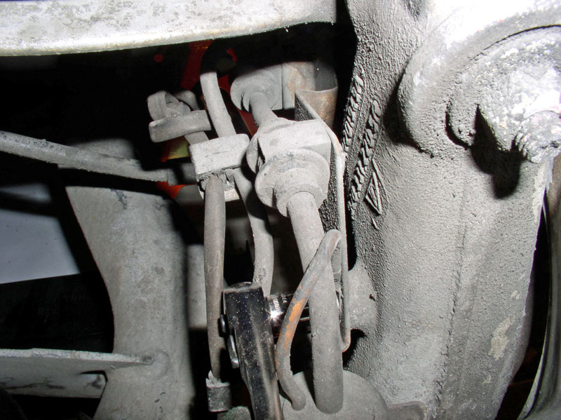
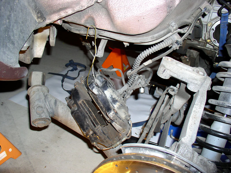
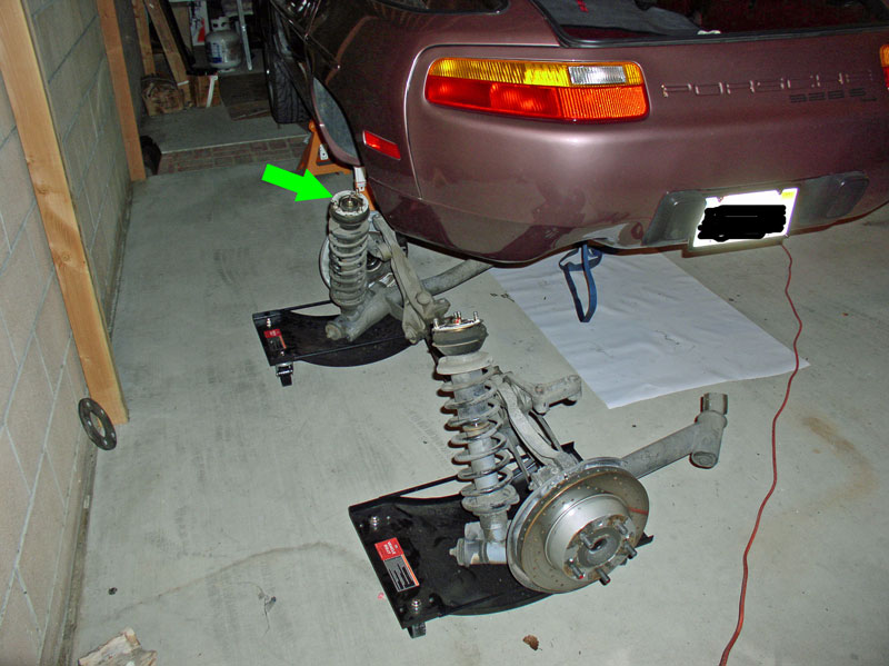
As the cross member is being lowered, keep an eye on the left hand side brake caliper that was resting on the upper control arm previously. When the lower control arm on that side cleared the carrier, I used the tab depicted in the picture below by the green arrow to suspend the caliper with some wire.
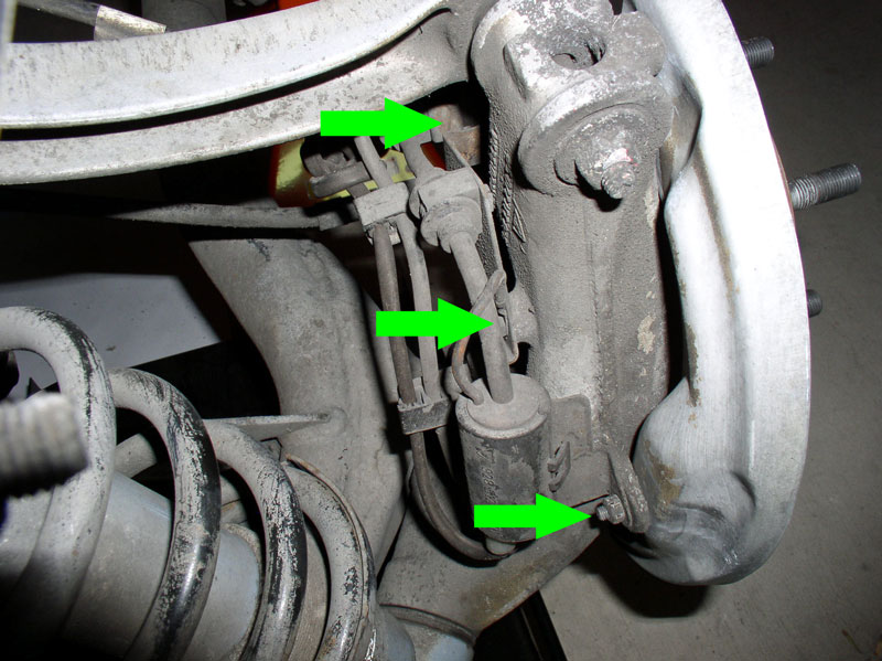
With the suspension lowered 6-8�, I then had more room to work on removing the brake wire bracket that�s attached to the hub. I had the choice of disconnecting all the wires or simply removing the bracket with all the wires attached and chose the later option. There are two 10mm bolts and one 10m nut that secures the bracket to the hub as depicted by the green arrows in the picture.
I removed the rearward nut first.
Followed by the center bolt.
And finally the forward bolt using an extension bar on the ratchet.
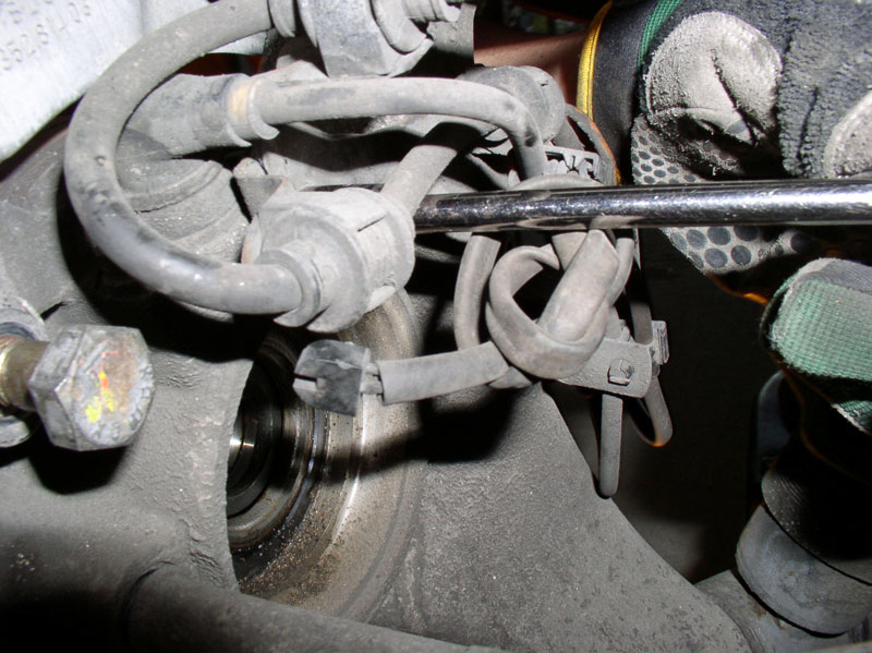
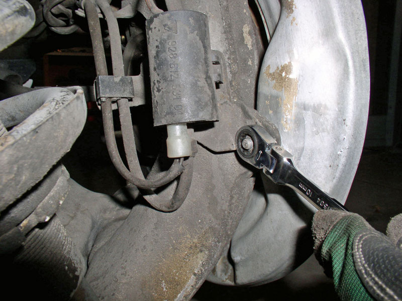
Also remove the speed sensor bracket. It�s secured using a 5mm Allen head bolt.
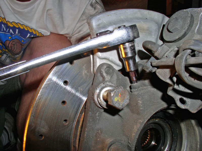
Pull the sensor upward with a twisting motion to remove the sensor from the hub. The tip was pretty dirty but cleaned up nicely later.
Lastly, I removed the wire harness from the cross member by simply pressing the connector out of its holder. I placed the now free bracket with the suspended caliper. Repeat for the other wheel.
I suspended the left side caliper and wire bracket from the tab indicated earlier and shown below.
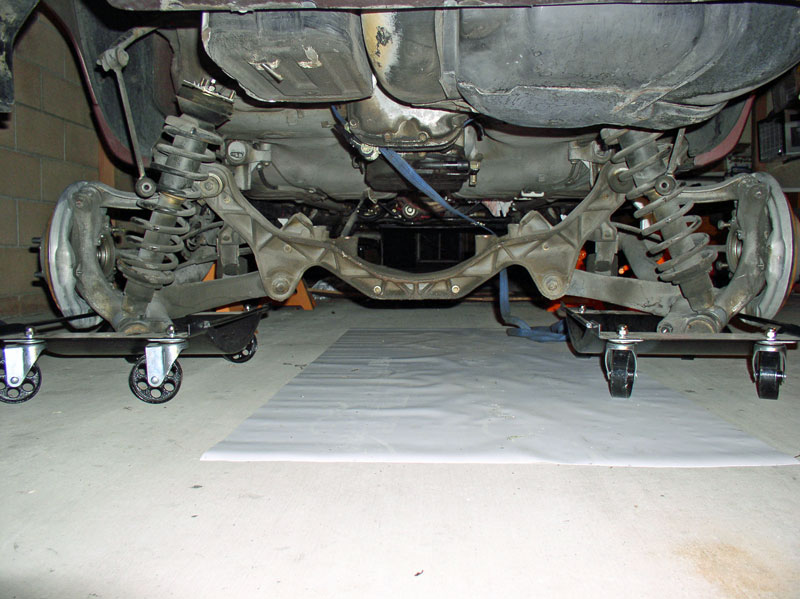
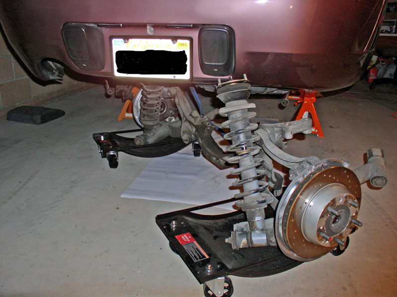
At this point the rear suspension should be free of any entanglements and you can lower slowly a few inches at a time checking to make sure nothing is hung up on the way down. The lower control arms should rest upon the car dollies (or suitable alternative) as shown below. Remove the floor jack.
I maneuvered the suspension to the right where the shock tower was nestled between the battery box and differential as shown. It can also be maneuvered out the other side exiting through the exhaust pipe cutout in the bumper cover.
I then swung the suspension rearward around the bumper. The shock tower is moveable so I put a towel on top of the studs and pushed the tower down or pulled it back so it would clear the bumper, the towel will help protect the paint on the bumper in case it gets away from you.
Continued....
I continued lowering the floor jack slowly a few inches at a time. As the cross member was being lowered, I applied downward force on the lower control arm to force it out of its carrier.
Eventually, the control arm became stubborn to push down so I used a long pry bar to lever against the carrier and push the bushing out. Be careful not to lever against the floorboard.
As the cross member is being lowered, keep an eye on the left hand side brake caliper that was resting on the upper control arm previously. When the lower control arm on that side cleared the carrier, I used the tab depicted in the picture below by the green arrow to suspend the caliper with some wire.
With the suspension lowered 6-8�, I then had more room to work on removing the brake wire bracket that�s attached to the hub. I had the choice of disconnecting all the wires or simply removing the bracket with all the wires attached and chose the later option. There are two 10mm bolts and one 10m nut that secures the bracket to the hub as depicted by the green arrows in the picture.
I removed the rearward nut first.
Followed by the center bolt.
And finally the forward bolt using an extension bar on the ratchet.
Also remove the speed sensor bracket. It�s secured using a 5mm Allen head bolt.
Pull the sensor upward with a twisting motion to remove the sensor from the hub. The tip was pretty dirty but cleaned up nicely later.
Lastly, I removed the wire harness from the cross member by simply pressing the connector out of its holder. I placed the now free bracket with the suspended caliper. Repeat for the other wheel.
I suspended the left side caliper and wire bracket from the tab indicated earlier and shown below.
At this point the rear suspension should be free of any entanglements and you can lower slowly a few inches at a time checking to make sure nothing is hung up on the way down. The lower control arms should rest upon the car dollies (or suitable alternative) as shown below. Remove the floor jack.
I maneuvered the suspension to the right where the shock tower was nestled between the battery box and differential as shown. It can also be maneuvered out the other side exiting through the exhaust pipe cutout in the bumper cover.
I then swung the suspension rearward around the bumper. The shock tower is moveable so I put a towel on top of the studs and pushed the tower down or pulled it back so it would clear the bumper, the towel will help protect the paint on the bumper in case it gets away from you.
Continued....
12-19-2010, 05:38 PM
#22
Team Owner
from the next set of pictures (removing the rear cross member)
You will also find factory fitted shims between the chassis cross memeber and or the trans to cross member,
make sure to install these in the same position when refitting.
I suggest to use white paint to mark the eccentrics, wire brush the area first.
For exact fitting of the rear cross member try fitting a drill bit into the slot of the edge of the cross member to the chassis rib , it is not uncommon to find the cross member off to one side or the other.
Carry on
12-19-2010, 05:39 PM
#23
Rennlist Member
Thread Starter
Join Date: Sep 2007
Location: Ridgecrest, California
Posts: 1,363
Likes: 0
Received 143 Likes
on
28 Posts
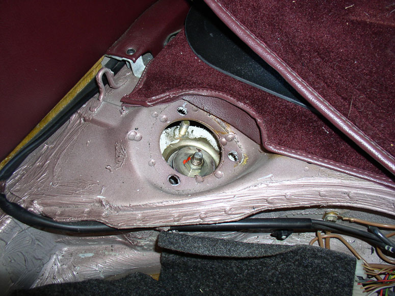
Once the suspension is clear of the bumper, simply roll it on out from under the car. You will notice the tops of the shock towers have a non-hardening sealant applied to prevent water from entering the rear hatch area. Depending on how much is left and the condition of the sealant, you may need to replace or add additional sealant when they are re-installed.
In the next chapter, I disconnect the TT from the engine.
In the next chapter, I disconnect the TT from the engine.
12-19-2010, 05:41 PM
#24
Race Director
More stunning work by Dwayne!!!!
I just saw this procedure in person during the trans replacement for the Estate.....having a heavy duty press is extremely helpful!!!
I just saw this procedure in person during the trans replacement for the Estate.....having a heavy duty press is extremely helpful!!!
12-19-2010, 05:56 PM
#25
Rennlist Member
Thread Starter
Join Date: Sep 2007
Location: Ridgecrest, California
Posts: 1,363
Likes: 0
Received 143 Likes
on
28 Posts
CH04 DISCONNECTING TT FROM ENGINE
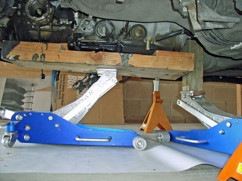
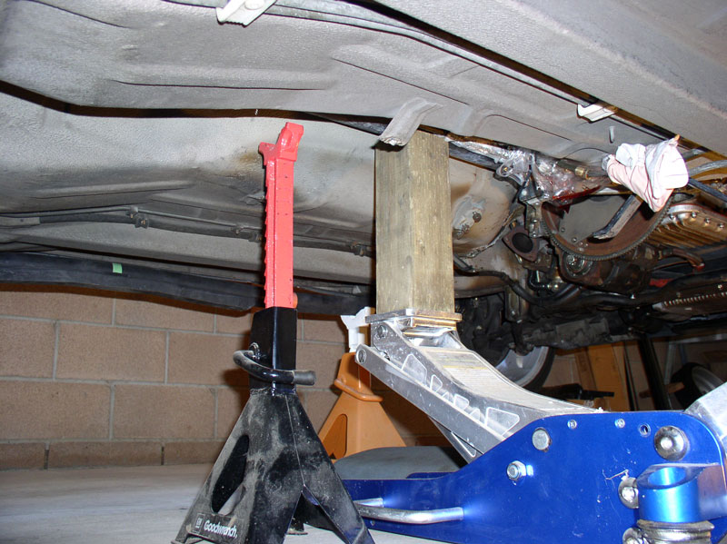
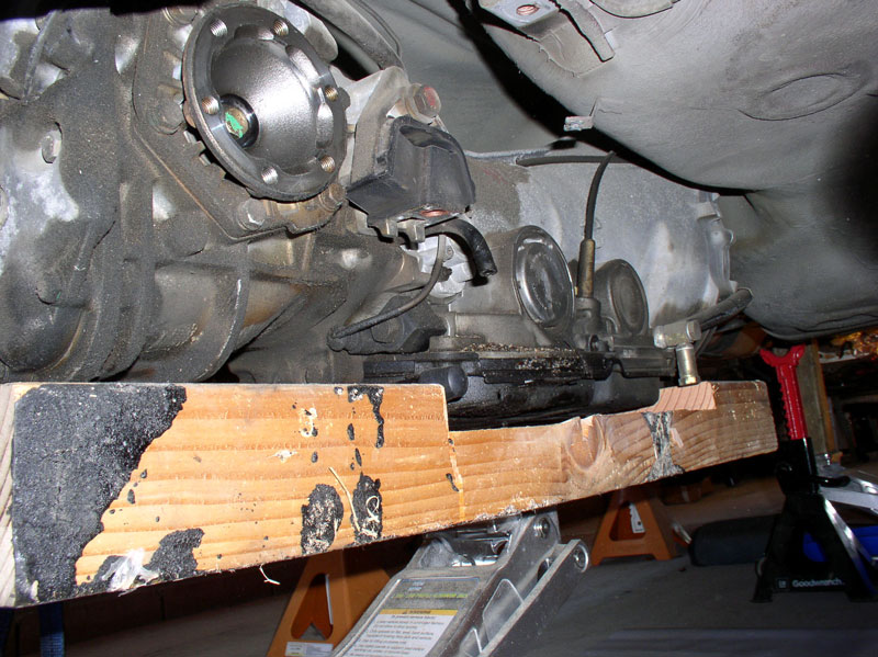
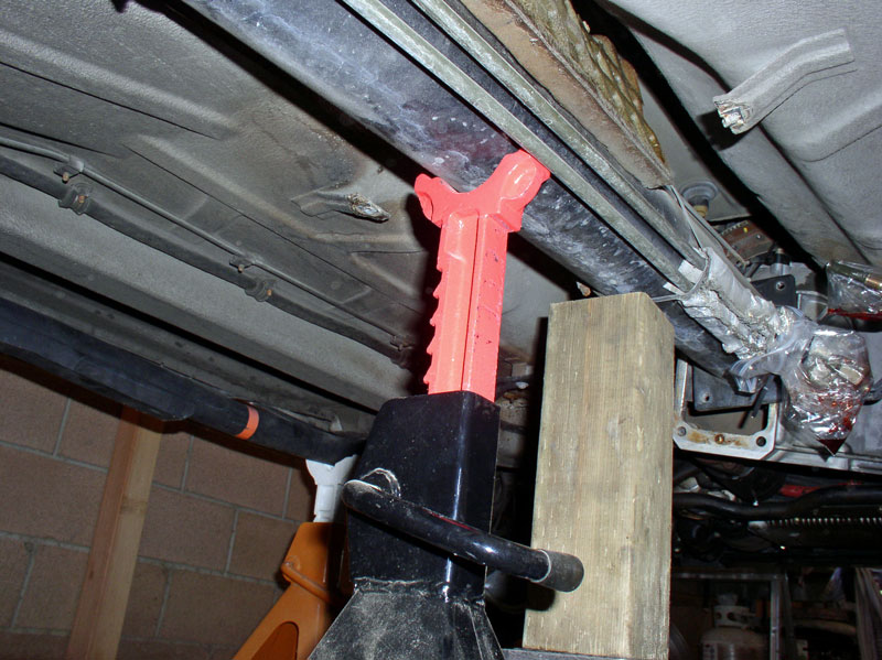
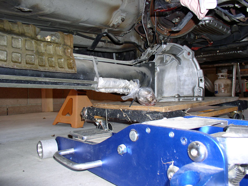
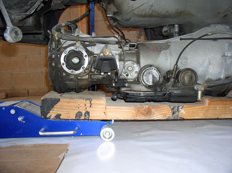
I needed to disconnect the drive shaft from the flywheel flex plate and disconnect the front of the TT from the engine. Before I did that, I needed to switch out the strap that was suspending the transmission and differential for the wooden platform I fabricated earlier. First, I supported the weight of the transmission just in front of the TC using a 4 X 4 scrap block. The floor jack was not tall enough to reach the TT. With the weight of the transmission supported, loosen and remove the lifting strap from the rear differential.
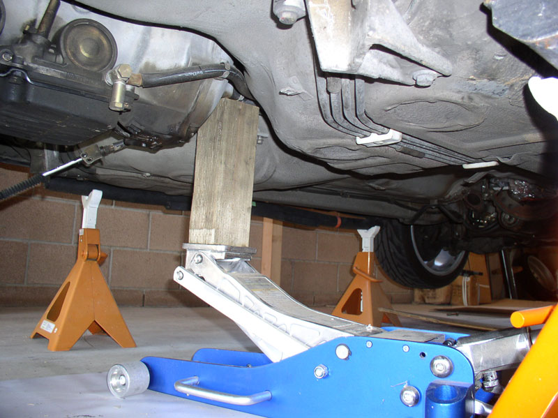
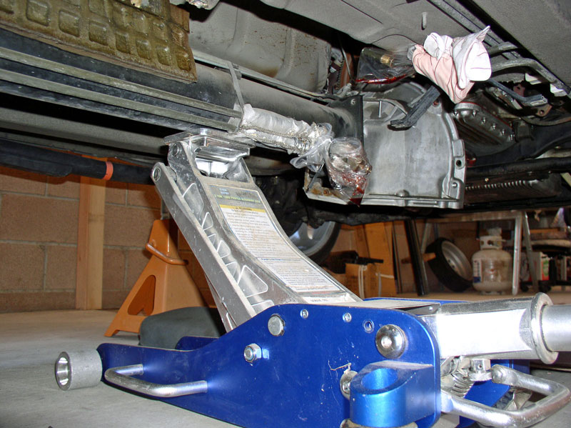
I positioned the wooden platform on the floor jack and maneuvered it into position as shown in the picture below. I then raised the floor jack to support the weight of the transmission and removed the other temporary floor jack with 4 X 4 block.
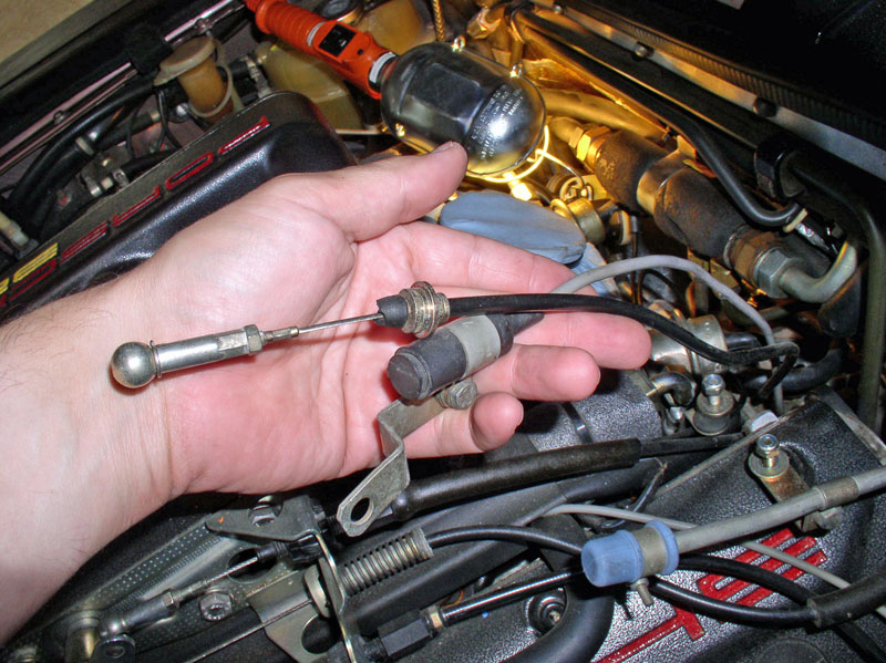
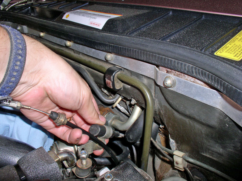
Before being able to slide the transmission rearward, it was necessary to disconnect the shift lever cable from the transmission. To gain clearance to access the cable, slowly lower the transmission using the floor jack and wooden platform. Lowering it 4-5� should be sufficient. Keep an eye on the transmission wiring harness in the rear hatch spare tire compartment to make sure it has enough slack in it when the transmission is lowered. When you can access the cable ball connector, you will need to remove the locking pin from the ball head. Pry upward on the wire locking pin so it rotates out from the ball head. Then pull the pin straight back out of the ball head.
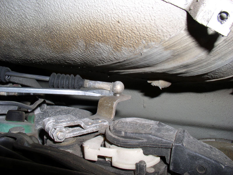
The lock pin is small and easy to loose so keep it nearby for a few minutes while you disconnect the ball connector from the shift selector.
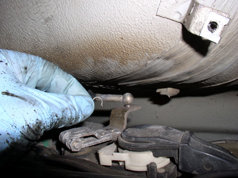
You should be able to pry the ball connector from the shift selector using a screwdriver as shown.
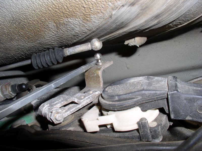
Next, loosen and remove the two 6mm Allen head bolts that secure the shift lever cable to the TC housing as shown below.
Pry out the shift lever cable from the �Y� clamp on the front of the TC housing as shown.
Finally, place the ball connector locking pin back into the ball connector as shown for safe keeping until it�s ready to re-install. When finished, raise the transmission back up to its original position using the floor jack.
Moving up to the flywheel, remove the six 15mm bolts that secure the drive shaft clamp flange to the flex plate as shown. These should have been loosened earlier when you relieved the tension on the flex plate. There is more than one way to disconnect the front of the drive shaft and TT from the engine. The first time I tried this, I disconnected the flex plate from the flywheel. This method worked OK but the flex plate did get in the way when trying to back out and lower the TT and front Bell Housing. I found that leaving the flex plate attached to the flywheel and disconnecting the drive shaft camp flange from the flex plate was A LOT easier to back out and remove the TT and front Bell Housing. Therefore, I would recommend that method.
Next, loosen and remove the lower Bell Housing to Engine bolts. There is one on each side of the engine and the bolts are 19mm.
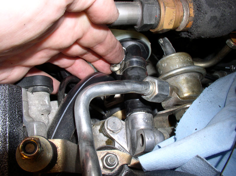
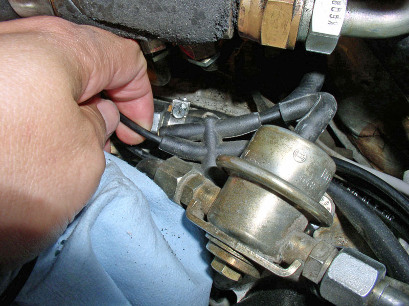
The upper Bell Housing bolts will need to be removed next. However, in order to reach the right side bolt, I needed to disconnect the heater valve hose from the cylinder head and move it out of the way to gain clearance to reach the upper bolt. Loosen the forward hose clamp as shown.
Then pull the short hose rearward to disconnect the hose from the cylinder head water port. I found that since the engine was cold, coolant was not present in this hose. Move the hose and valve assembly out of the way being careful not to dislodge the vacuum line that is connected to the valve.
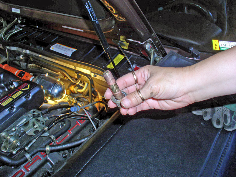
I used an extended closed end wrench to get at the 19mm bolt. It�s a good idea to use gloves and a towel on the end of the wrench so you don�t crush your hands while trying to break the bolt loose. Also ensure the wrench is fully seated on the bolt head so as not to strip the head. You can also use a pipe over the end of the wrench to provide additional leverage.
The bolt should look like this when removed.
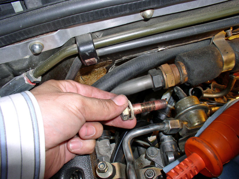
After the right upper Bell Housing bolt is removed. Reconnect the heater control valve hose to the cylinder head water port and tighten the clamp to prevent coolant leakage while continuing to work.
Continued....
I needed to disconnect the drive shaft from the flywheel flex plate and disconnect the front of the TT from the engine. Before I did that, I needed to switch out the strap that was suspending the transmission and differential for the wooden platform I fabricated earlier. First, I supported the weight of the transmission just in front of the TC using a 4 X 4 scrap block. The floor jack was not tall enough to reach the TT. With the weight of the transmission supported, loosen and remove the lifting strap from the rear differential.
I positioned the wooden platform on the floor jack and maneuvered it into position as shown in the picture below. I then raised the floor jack to support the weight of the transmission and removed the other temporary floor jack with 4 X 4 block.
Before being able to slide the transmission rearward, it was necessary to disconnect the shift lever cable from the transmission. To gain clearance to access the cable, slowly lower the transmission using the floor jack and wooden platform. Lowering it 4-5� should be sufficient. Keep an eye on the transmission wiring harness in the rear hatch spare tire compartment to make sure it has enough slack in it when the transmission is lowered. When you can access the cable ball connector, you will need to remove the locking pin from the ball head. Pry upward on the wire locking pin so it rotates out from the ball head. Then pull the pin straight back out of the ball head.
The lock pin is small and easy to loose so keep it nearby for a few minutes while you disconnect the ball connector from the shift selector.
You should be able to pry the ball connector from the shift selector using a screwdriver as shown.
Next, loosen and remove the two 6mm Allen head bolts that secure the shift lever cable to the TC housing as shown below.
Pry out the shift lever cable from the �Y� clamp on the front of the TC housing as shown.
Finally, place the ball connector locking pin back into the ball connector as shown for safe keeping until it�s ready to re-install. When finished, raise the transmission back up to its original position using the floor jack.
Moving up to the flywheel, remove the six 15mm bolts that secure the drive shaft clamp flange to the flex plate as shown. These should have been loosened earlier when you relieved the tension on the flex plate. There is more than one way to disconnect the front of the drive shaft and TT from the engine. The first time I tried this, I disconnected the flex plate from the flywheel. This method worked OK but the flex plate did get in the way when trying to back out and lower the TT and front Bell Housing. I found that leaving the flex plate attached to the flywheel and disconnecting the drive shaft camp flange from the flex plate was A LOT easier to back out and remove the TT and front Bell Housing. Therefore, I would recommend that method.
Next, loosen and remove the lower Bell Housing to Engine bolts. There is one on each side of the engine and the bolts are 19mm.
The upper Bell Housing bolts will need to be removed next. However, in order to reach the right side bolt, I needed to disconnect the heater valve hose from the cylinder head and move it out of the way to gain clearance to reach the upper bolt. Loosen the forward hose clamp as shown.
Then pull the short hose rearward to disconnect the hose from the cylinder head water port. I found that since the engine was cold, coolant was not present in this hose. Move the hose and valve assembly out of the way being careful not to dislodge the vacuum line that is connected to the valve.
I used an extended closed end wrench to get at the 19mm bolt. It�s a good idea to use gloves and a towel on the end of the wrench so you don�t crush your hands while trying to break the bolt loose. Also ensure the wrench is fully seated on the bolt head so as not to strip the head. You can also use a pipe over the end of the wrench to provide additional leverage.
The bolt should look like this when removed.
After the right upper Bell Housing bolt is removed. Reconnect the heater control valve hose to the cylinder head water port and tighten the clamp to prevent coolant leakage while continuing to work.
Continued....
12-19-2010, 06:07 PM
#26
Rennlist Member
Thread Starter
Join Date: Sep 2007
Location: Ridgecrest, California
Posts: 1,363
Likes: 0
Received 143 Likes
on
28 Posts
I used the same wrench to get access to the left upper Bell Housing bolt. I slid the wrench down inside the fuel return line �loop� as pictured. There was enough allowable movement to break the bolt loose.
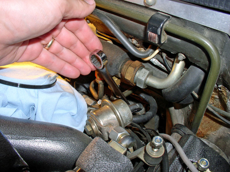
I continued loosening the bolt until it was easy enough to turn by hand. Unfortunately, my hand did not fit in the tight space between the bolt and the firewall.
My solution was to enlist the help of my wife and her extra small hands. She could reach the bolt, finish removing it and bring it back up.
Locate and disconnect the vacuum line leading rearward toward the transmission. This vacuum line will come out with the TT. Your vacuum manifold may be a 5 port or a 7 port.
The Bowden cable and flywheel sensor lead will also come out with the TT when it is lowered and removed. Ensure both of these are free to slide out when the TT is lowered and removed.
Next, I went back under the car and placed a 4 X 4 block on the floor jack to support the forward end of the TT as shown. I also set a jack stand under the TT for added safety.
Next, I removed the two lower 17mm bolts from the rear of the Bell Housing.
To remove the two upper 17mm bolts from the Bell Housing, I used the �T� handle ratchet with a 3� extension. Break the bolt loose first with the ratchet then use the �T� handle to quickly remove the bolts.
Separate the TT from the rear of the Bell Housing using a pry bar as shown. This will slide the transmission and TT rearward an inch or so.
I used a pry bar to apply light force to separate the Bell Housing from the engine block. If the Bell Housing does not separate with light force applied, use another surface to apply leverage rather than use the flywheel. Mine came apart easily.
Separate the Bell Housing enough for the Housing to clear the locating pins. There is one pin on each side of the engine block.
The TT and transmission are now ready to be lowered.
12-19-2010, 06:23 PM
#27
Rennlist Member
Thread Starter
Join Date: Sep 2007
Location: Ridgecrest, California
Posts: 1,363
Likes: 0
Received 143 Likes
on
28 Posts
CH05 REMOVING TRANSMISSION AND TT
Before lowering the transmission, keep an eye on the transmission harness to make sure it does not hang up on the access hole in the spare tire compartment. With the transmission raised, there was a bit of resistance when pushing the harness through the hole so I decided to lower the transmission a bit then push the harness through.
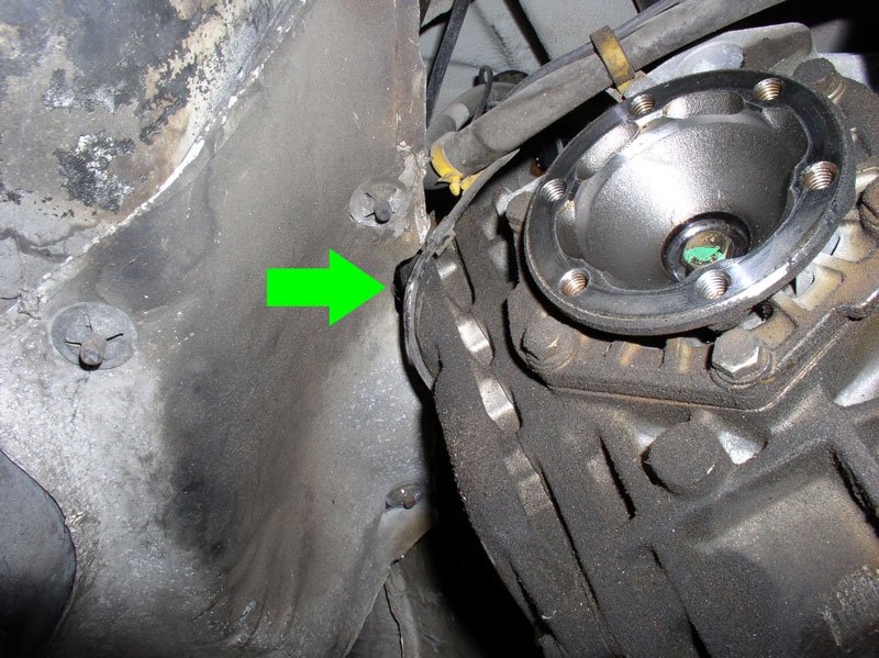
I carefully lowered the transmission a few inches at a time checking clearances on all sides to make sure I didn�t forget something still connected. Each time I lowered the transmission, I would also lower the front of the TT. Having the bell housing disconnected from the TT made it a lot easier to maneuver the TT down without getting hung up on something.
Keep an eye on the rear of the differential and the heat shield in front of the fuel tank. When I pried the TT back away from the front bell housing, it backed the transmission up a bit. There�s still enough room, though, to lower the transmission without damaging the heat shield.
After lowering the transmission a bit, I pulled the transmission harness through the access hole from underneath�.
�.and pushed the harness connector through from above.
Each time I lowered the transmission a few inches, I would also lower the TT a few inches in order to keep things level. When the TT has been lowered several inches, you will need to place a jack stand under the TT to hold it in place while you remove the 4 X 4 block.
Then raise the floor jack to support the TT and remove the jack stand. Now you will be able to lower the TT all the way to the ground.
As you are lowering the TT, make sure the Bowden cable and flywheel sensor cables are free and are not hanging up on anything.
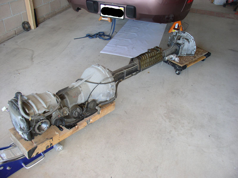
I used a furniture dolly and piece of scrap plywood to support the forward end of the TT.
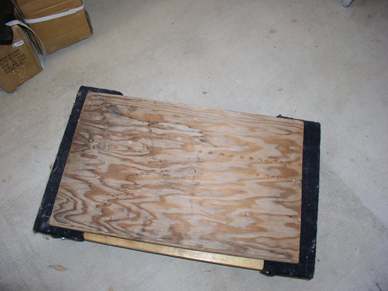
I placed the TT on the dolly and removed the floor jack.
And lowered the transmission all the way down on the floor jack.
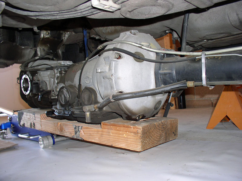
I had to slide the transmission platform forward on the floor jack which gave me a few more inches of clearance to remove the transmission from the rear of the car.
I carefully pulled the transmission out from the rear of the car without any trouble.
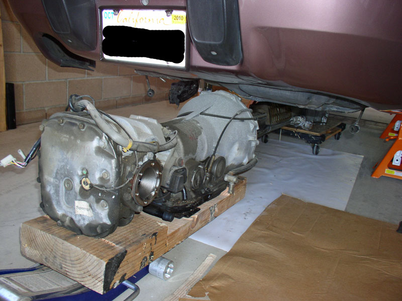
Once the unit is clear, it�s fairly easy to move around. However, I pulled the transmission back up on the floor jack to provide more balance and stability for moving.
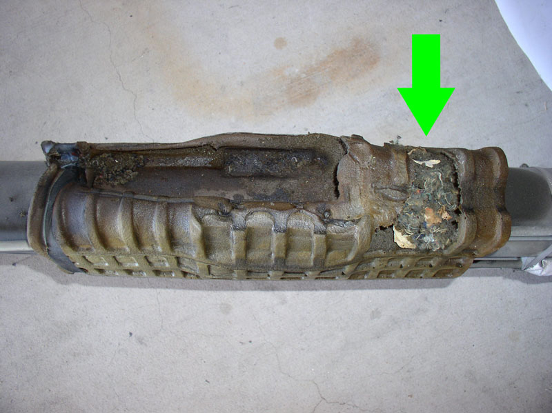
Upon inspection of the sound absorber, there had been critters living in the foam at some point while the car was in the possession of the previous owner. Critters long gone by now.
Continued....
Before lowering the transmission, keep an eye on the transmission harness to make sure it does not hang up on the access hole in the spare tire compartment. With the transmission raised, there was a bit of resistance when pushing the harness through the hole so I decided to lower the transmission a bit then push the harness through.
I carefully lowered the transmission a few inches at a time checking clearances on all sides to make sure I didn�t forget something still connected. Each time I lowered the transmission, I would also lower the front of the TT. Having the bell housing disconnected from the TT made it a lot easier to maneuver the TT down without getting hung up on something.
Keep an eye on the rear of the differential and the heat shield in front of the fuel tank. When I pried the TT back away from the front bell housing, it backed the transmission up a bit. There�s still enough room, though, to lower the transmission without damaging the heat shield.
After lowering the transmission a bit, I pulled the transmission harness through the access hole from underneath�.
�.and pushed the harness connector through from above.
Each time I lowered the transmission a few inches, I would also lower the TT a few inches in order to keep things level. When the TT has been lowered several inches, you will need to place a jack stand under the TT to hold it in place while you remove the 4 X 4 block.
Then raise the floor jack to support the TT and remove the jack stand. Now you will be able to lower the TT all the way to the ground.
As you are lowering the TT, make sure the Bowden cable and flywheel sensor cables are free and are not hanging up on anything.
I used a furniture dolly and piece of scrap plywood to support the forward end of the TT.
I placed the TT on the dolly and removed the floor jack.
And lowered the transmission all the way down on the floor jack.
I had to slide the transmission platform forward on the floor jack which gave me a few more inches of clearance to remove the transmission from the rear of the car.
I carefully pulled the transmission out from the rear of the car without any trouble.
Once the unit is clear, it�s fairly easy to move around. However, I pulled the transmission back up on the floor jack to provide more balance and stability for moving.
Upon inspection of the sound absorber, there had been critters living in the foam at some point while the car was in the possession of the previous owner. Critters long gone by now.
Continued....
12-19-2010, 06:26 PM
#28
Rennlist Member
Thread Starter
Join Date: Sep 2007
Location: Ridgecrest, California
Posts: 1,363
Likes: 0
Received 143 Likes
on
28 Posts
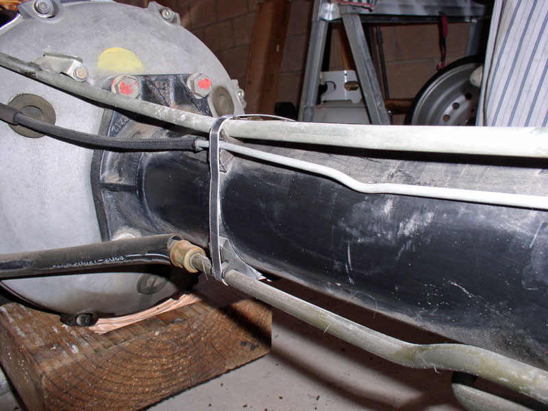
Remove the sound absorber next. It is only attached to the TT by a strap of tape at the rear end.
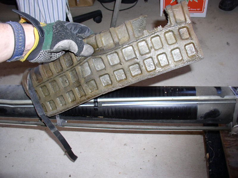
After removing the sound absorber and cleaning off the TT, I marked the location of the start and stop edges of the sound absorber so I�d know where to locate it when re-installing the TT and I also marked the locations of the clamps that secured the vacuum and oil cooler lines using some yellow paint.
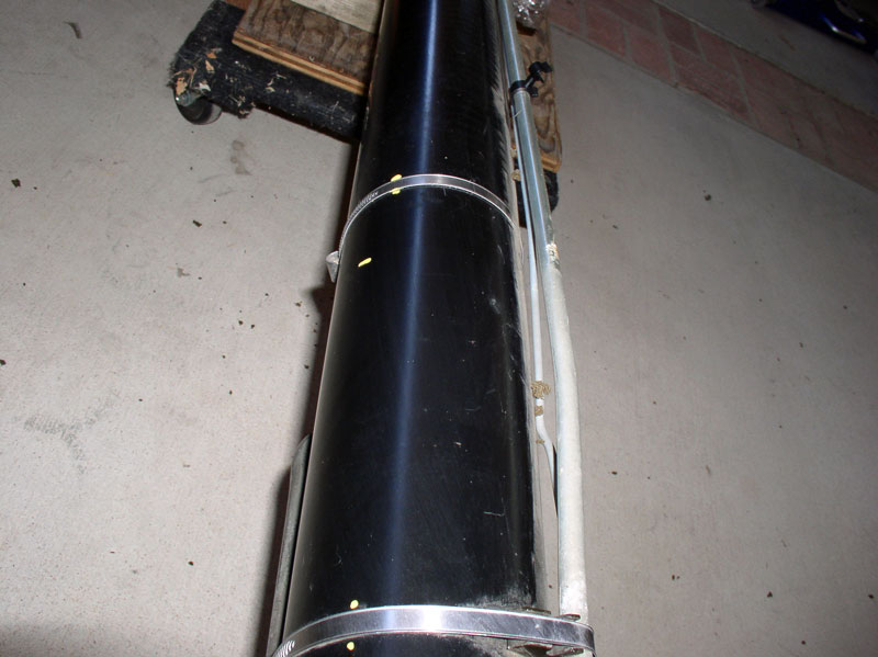
I took reference pictures of how the Bowden cable, vacuum line and transmission fluid cooler lines were oriented for the re-installation process later.
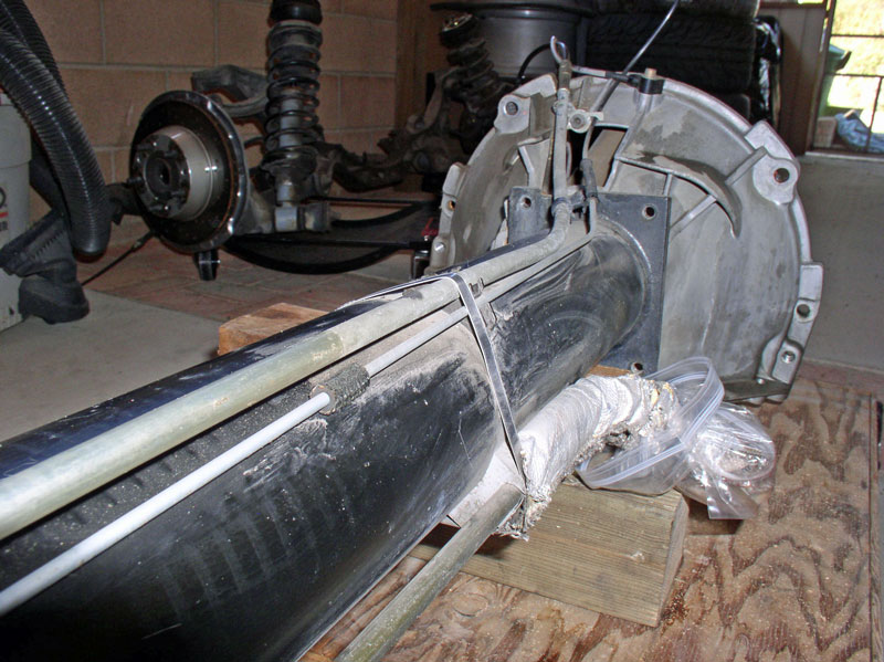
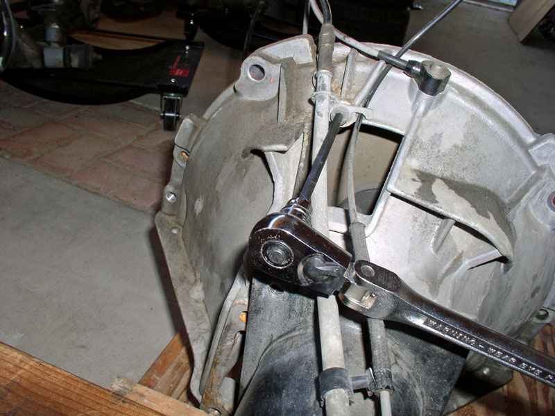
Here�s a shot at the front bell housing for reference.
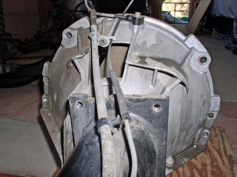
�.and a shot at the TC.
Now I was ready to disconnect the TT from the transmission.
After removing the sound absorber and cleaning off the TT, I marked the location of the start and stop edges of the sound absorber so I�d know where to locate it when re-installing the TT and I also marked the locations of the clamps that secured the vacuum and oil cooler lines using some yellow paint.
I took reference pictures of how the Bowden cable, vacuum line and transmission fluid cooler lines were oriented for the re-installation process later.
Here�s a shot at the front bell housing for reference.
�.and a shot at the TC.
Now I was ready to disconnect the TT from the transmission.
12-19-2010, 06:45 PM
#29
Rennlist Member
Thread Starter
Join Date: Sep 2007
Location: Ridgecrest, California
Posts: 1,363
Likes: 0
Received 143 Likes
on
28 Posts
CH06 DISCONNECTING TT FROM TRANSMISSION
Remove the small Allen Head bolt that secures the Bowden cable and vacuum line to the bell housing. It takes a 5mm Allen head socket.
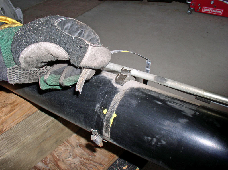
Begin removing the 3 clamps along the TT that secure the Bowden cable, vacuum line and oil cooler lines to the TT. You can use a flat blade screwdriver or small socket wrench. I marked the TT with paint to I could re-install the clamp in the same location when putting it back together.
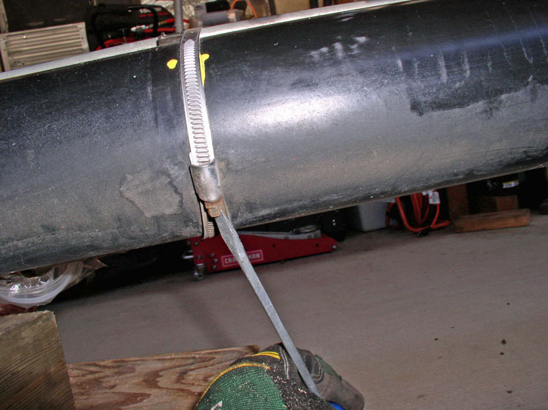
When removing the clamps, I noted the location each clamp was removed from (front, middle or rear of the TT) so I could place the clamps in the same location on re-install. This was mainly due to the fact I observed the clamps were bent differently at different locations along the TT.
Next, I removed the bolt at the TC that secures the Bowden cable. It takes a 10mm socket.
Before prying/removing the drive shaft, I measured the forward TT Bearing distance from the front of the TT just for reference. It was about 9 7/8� from the front of the TT.
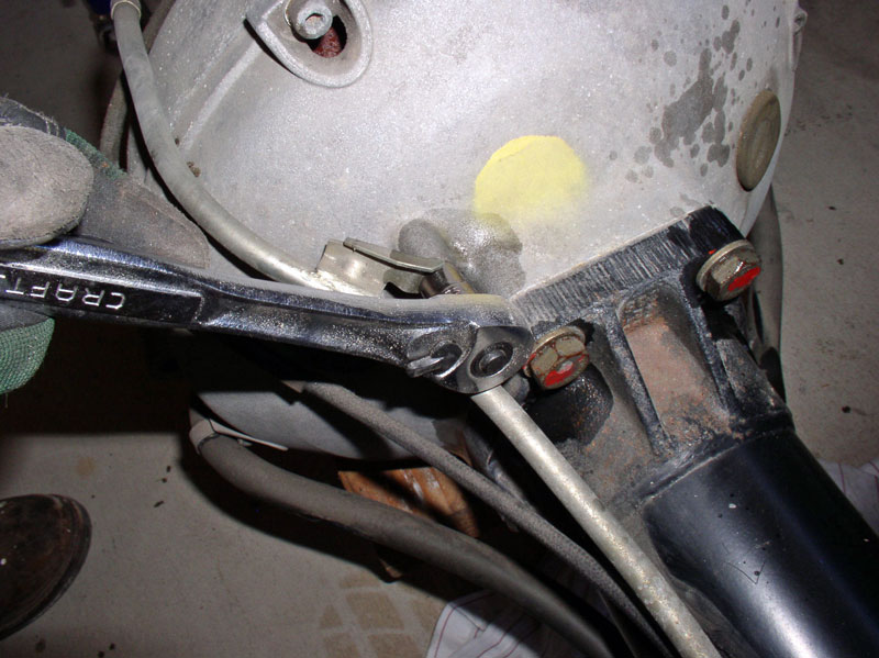
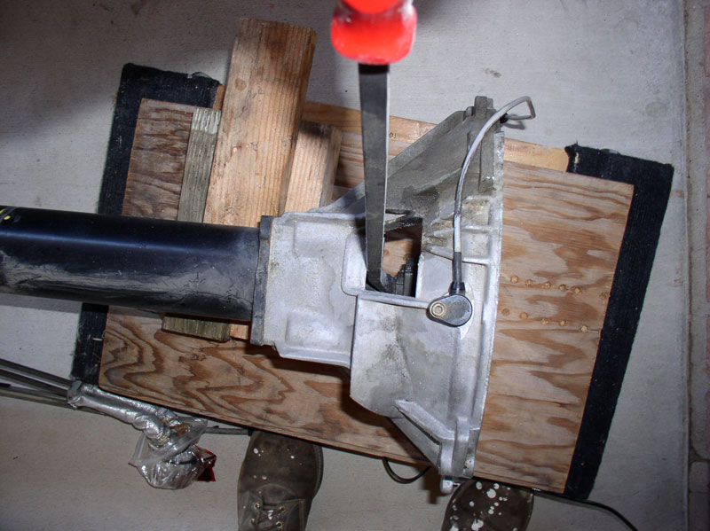
Next, I pried the drive shaft out of the TT. To do this, I secured the bell housing to the TT using a couple of the bolts removed earlier. I used a long pry bar to give additional leverage. Initially, you can use the inspection port pictured below to lever against. Lever the pry bar against the drive shaft clamp. The clamp should hold since the clamp pinch bolt has not been loosened yet.
When I had pried the shaft out far enough that I could no longer lever against the clamp, I inserted scrap 2 X 6 lumber of varying lengths to continue prying the drive shaft out of the TT.
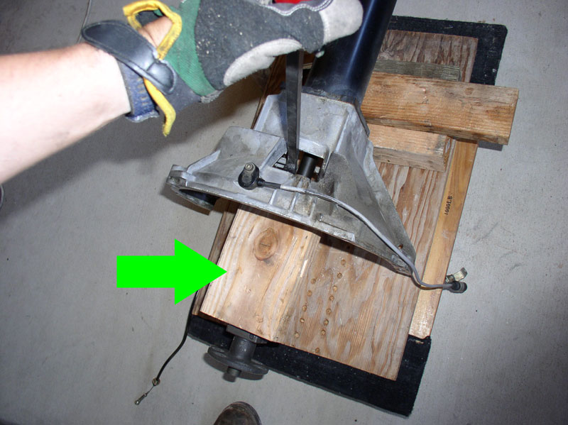
Eventually, I needed to use longer scrap lumber and lever from outside the bell housing as depicted in the picture below.
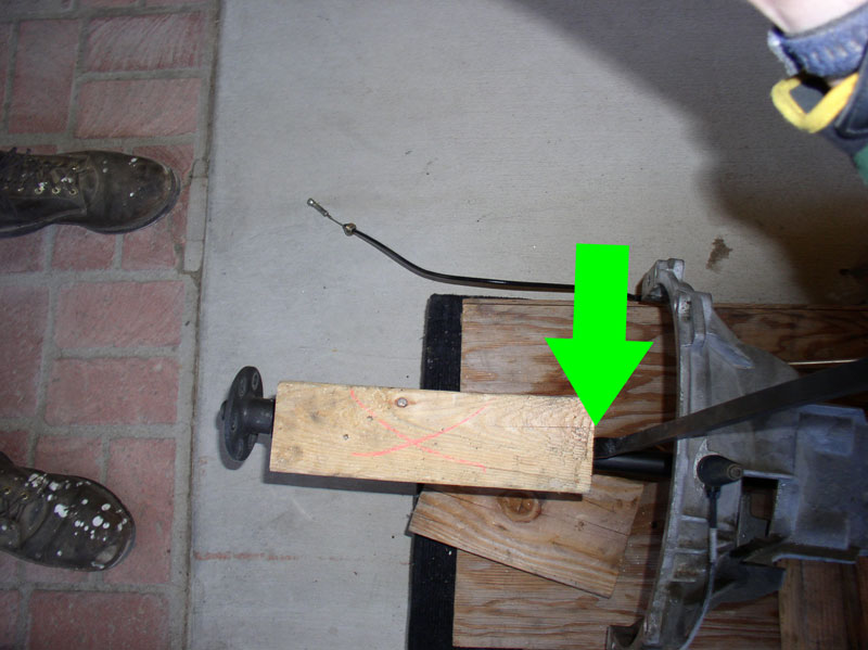
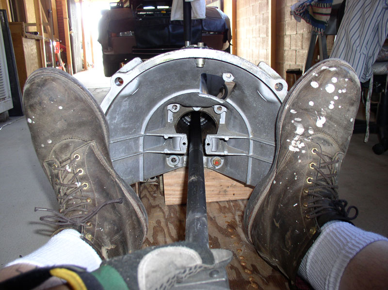
When the drive shaft had been pried out far enough that it had cleared the rear bearing and now was only being held by the forward bearing, I was able to simply place my feet against the bell housing and grasp the end of the drive shaft at the clamp and pull the drive shaft out the remaining distance. If the drive shaft is stubborn, try spraying some WD-40 on the drive shaft at the bearing and stand the TT on end so the WD-40 will flow down and lubricate the drive shaft and bearing sleeve for easier removal.
You will notice the rear end of the drive shaft has a groove machined in the splines for the pinch bolt. This is a 25mm drive shaft.
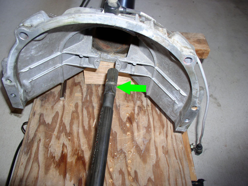
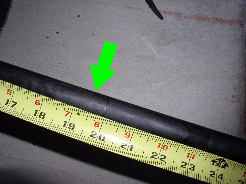
You may also notice the wear marks on the drive shaft where the TT bearing sleeves were located.
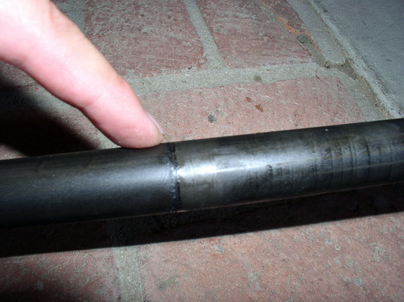
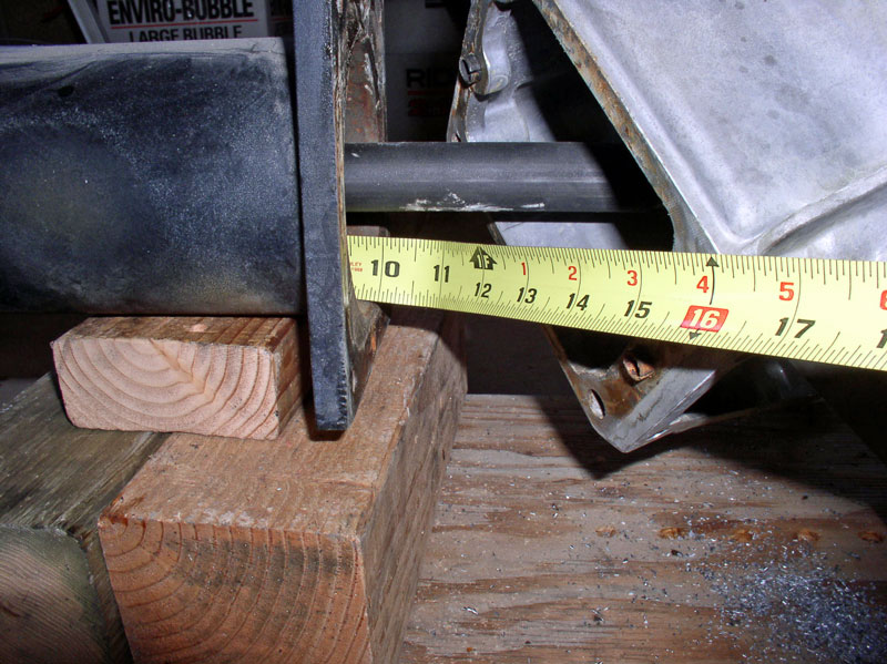
Looking at the bearing sleeve wear marks on the drive shaft, I measured the distance from the rear of the drive shaft to the first wear mark indicating the location of the rear bearing from the rear of the drive shaft. In this case, it was between 19 � and 20 inches from the rear of the drive shaft.
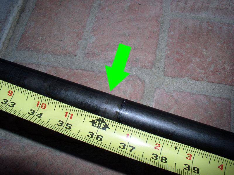
Measuring from the rear of the drive shaft, the forward bearing was about 36 inches. I made note of these distances in case I was going to replace the bearings with OEM bearings. In this case, I will be replacing the OEM bearings with Constantine�s Super Bearings.
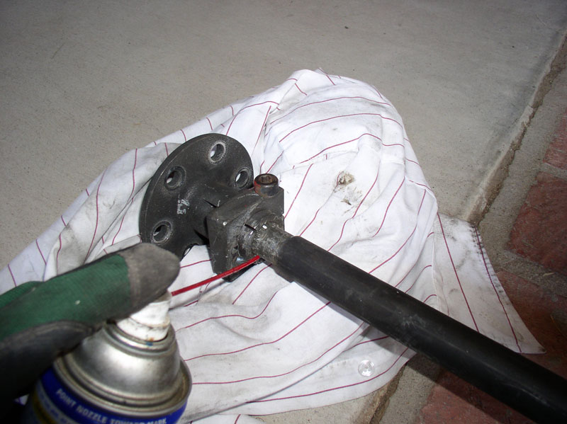
As an extra precaution to make removal of the drive shaft clamp easier, I sprayed some WD-40 on the splines before loosening the bolt
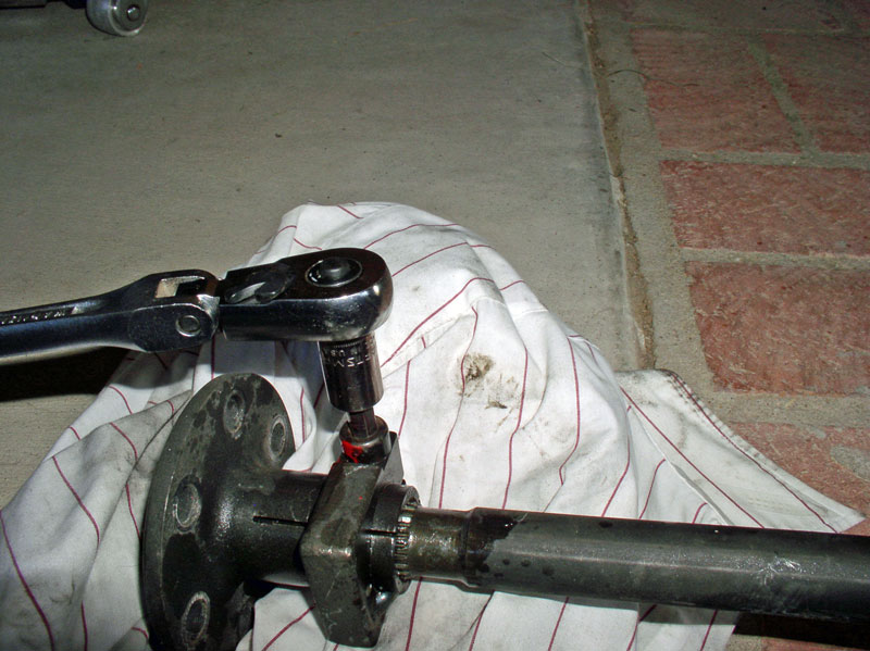
I then loosened the pinch bolt using an 8mm Allen head socket. I used a long handle ratchet to get more leverage.
Continued....
Remove the small Allen Head bolt that secures the Bowden cable and vacuum line to the bell housing. It takes a 5mm Allen head socket.
Begin removing the 3 clamps along the TT that secure the Bowden cable, vacuum line and oil cooler lines to the TT. You can use a flat blade screwdriver or small socket wrench. I marked the TT with paint to I could re-install the clamp in the same location when putting it back together.
When removing the clamps, I noted the location each clamp was removed from (front, middle or rear of the TT) so I could place the clamps in the same location on re-install. This was mainly due to the fact I observed the clamps were bent differently at different locations along the TT.
Next, I removed the bolt at the TC that secures the Bowden cable. It takes a 10mm socket.
Before prying/removing the drive shaft, I measured the forward TT Bearing distance from the front of the TT just for reference. It was about 9 7/8� from the front of the TT.
Next, I pried the drive shaft out of the TT. To do this, I secured the bell housing to the TT using a couple of the bolts removed earlier. I used a long pry bar to give additional leverage. Initially, you can use the inspection port pictured below to lever against. Lever the pry bar against the drive shaft clamp. The clamp should hold since the clamp pinch bolt has not been loosened yet.
When I had pried the shaft out far enough that I could no longer lever against the clamp, I inserted scrap 2 X 6 lumber of varying lengths to continue prying the drive shaft out of the TT.
Eventually, I needed to use longer scrap lumber and lever from outside the bell housing as depicted in the picture below.
When the drive shaft had been pried out far enough that it had cleared the rear bearing and now was only being held by the forward bearing, I was able to simply place my feet against the bell housing and grasp the end of the drive shaft at the clamp and pull the drive shaft out the remaining distance. If the drive shaft is stubborn, try spraying some WD-40 on the drive shaft at the bearing and stand the TT on end so the WD-40 will flow down and lubricate the drive shaft and bearing sleeve for easier removal.
You will notice the rear end of the drive shaft has a groove machined in the splines for the pinch bolt. This is a 25mm drive shaft.
You may also notice the wear marks on the drive shaft where the TT bearing sleeves were located.
Looking at the bearing sleeve wear marks on the drive shaft, I measured the distance from the rear of the drive shaft to the first wear mark indicating the location of the rear bearing from the rear of the drive shaft. In this case, it was between 19 � and 20 inches from the rear of the drive shaft.
Measuring from the rear of the drive shaft, the forward bearing was about 36 inches. I made note of these distances in case I was going to replace the bearings with OEM bearings. In this case, I will be replacing the OEM bearings with Constantine�s Super Bearings.
As an extra precaution to make removal of the drive shaft clamp easier, I sprayed some WD-40 on the splines before loosening the bolt
I then loosened the pinch bolt using an 8mm Allen head socket. I used a long handle ratchet to get more leverage.
Continued....
