
1987 FRONT BUMPER COVER REPLACEMENT PROCEDURE w/PICs
 12-26-2010, 12:55 PM
#1
Rennlist Member
Thread Starter
Join Date: Sep 2007
Location: Ridgecrest, California
Posts: 1,363
Likes: 0
Received 143 Likes
on
28 Posts
1987 FRONT BUMPER COVER REPLACEMENT PROCEDURE
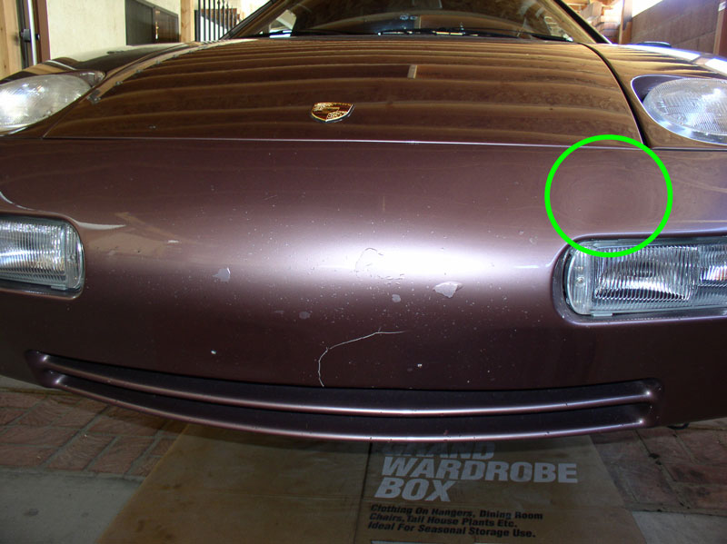
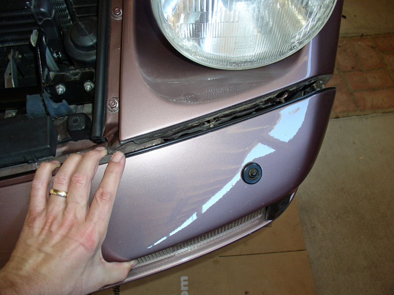
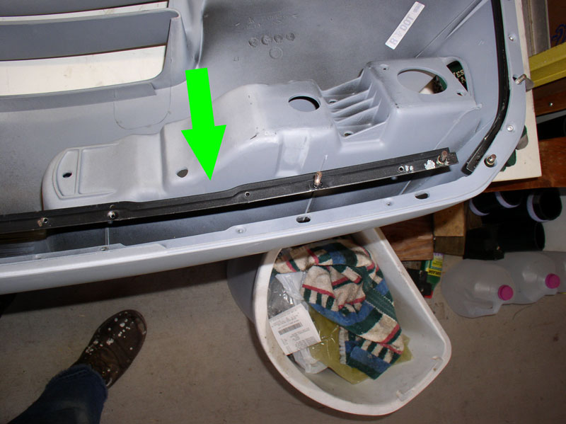
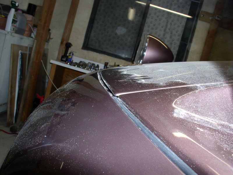
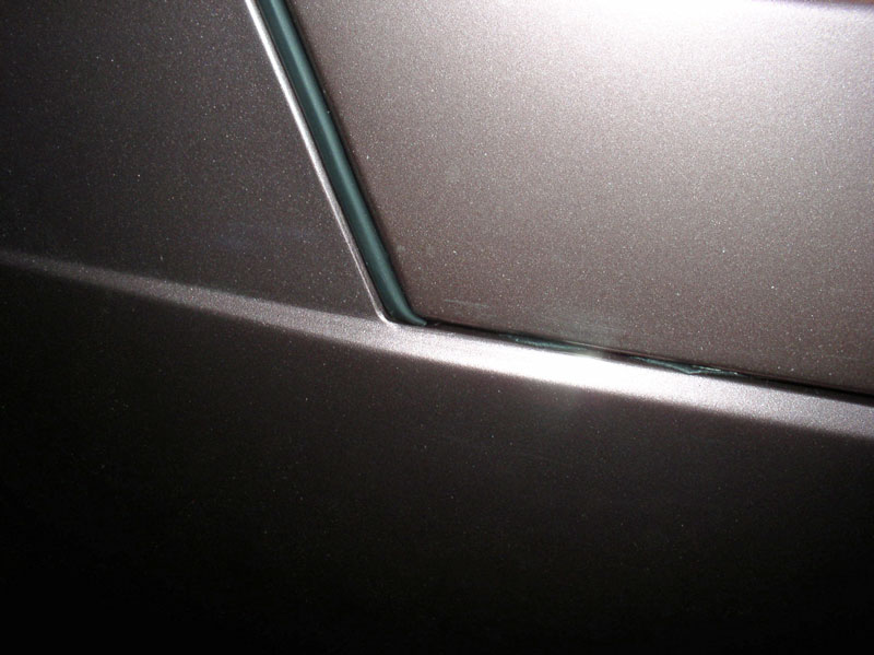
We’ve had Virginia (’87) for a couple of years now and the front bumper cover seemed to be getting noticeably worse as the weeks went by. The front bumper cover had obviously been repaired and repainted at some time earlier well before we purchased the car. You can see the crack below where something was struck. The paint was peeling and there was a depression or warp in the cover just above the left fog lamp assembly as depicted below by the green circle.
We considered having this bumper cover repaired again and repainted but I was not confident the warp could be fully removed. I looked as some refurbished covers and they too did not appear to be perfectly smooth as the cover on Idaho (my baseline for comparison). So we opted to purchase a brand new Porsche bumper cover and have it painted. The brand new cover came primed and upon inspection it was perfectly shaped with no warps or ripples by sight and touch. I did the removal and install of the cover and had a local paint and body shop perform the color matching and painting.
This procedure details the process I used to remove and re-install a new bumper cover. This was my first bumper cover removal and I thought I'd take a picture or two along the way to help other DIYers that may want to try this repair for the first time themselves. It would also apply if you are simply repairing/repainting your existing bumper cover.
WARNING: This is a Newbie-rated procedure and contains step-by-step instructions for the removal and installation process and contains approximately 135 pictures.
PARTS, TOOLS AND PREPARATION
For this job I purchased the following parts:
1. New Bumper cover (928.505.113.20) – refurbished are also available or you can have your original cover repaired.
2. Beading for front bumper (2) (928.505.143.03)
Optional parts that may be considered if you have cracked or broken parts:
1. Front Spoiler (928.505.071.21) I couldn’t get the spoiler for the ’87 MY so the part number here reflects what is available for ’90 and later.
2. Front Spoiler Install kit (928.505.071.21KT) through 928 International
3. Headlight Squirters (928.528.071.02) if yours are cracked or faded.
4. Left Splash Shield (928.504.221.11)
5. Right Splash Shield (928.504.222.11)
6. Splash Shield Seal Left Long (928.504.223.07)
7. Splash Shield Seal Left Top (928.504.223.05)
8. Splash Shield Seal Left Inside (928.504.223.04)
9. Splash Shield Seal Right (928.504.223.08)
10. Splash Shield Seal Left/Right (2) (928.504.223.09)
I used the following Special Tools for the job:
1. Porken’s Lift Bars
2. HF 6-Ton Jack Stands
3. Stanley Blind Riveter (available at Home Depot)
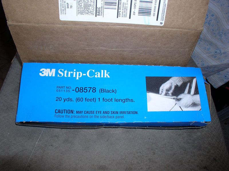
I also used some non-hardening automotive sealant that is to go between the bumper cover and the fender mating surfaces just in front of the front wheels. The picture below is the 3M sealant I used:
The only Preparation I did for the job was researching what options were available for the front bumper cover (new, refurbished, or repair existing), researching and obtaining an estimate of the paint work from an auto body and paint shop, ordering parts, and clearing a suitable workbench area to work on the bumper cover once removed.
REMOVING BUMPER COVER
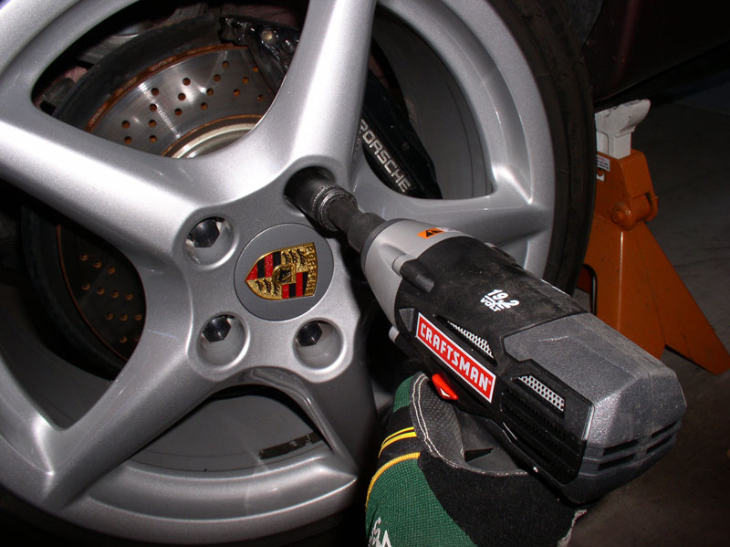
Start by loosening the front wheel lug nuts, raising the car (I used lift bars and jack stands), and removing the front wheels. Once the car is lifted, you will need to remove the belly pans as the front belly pan is attached to the spoiler and the spoiler will be removed with the bumper cover.
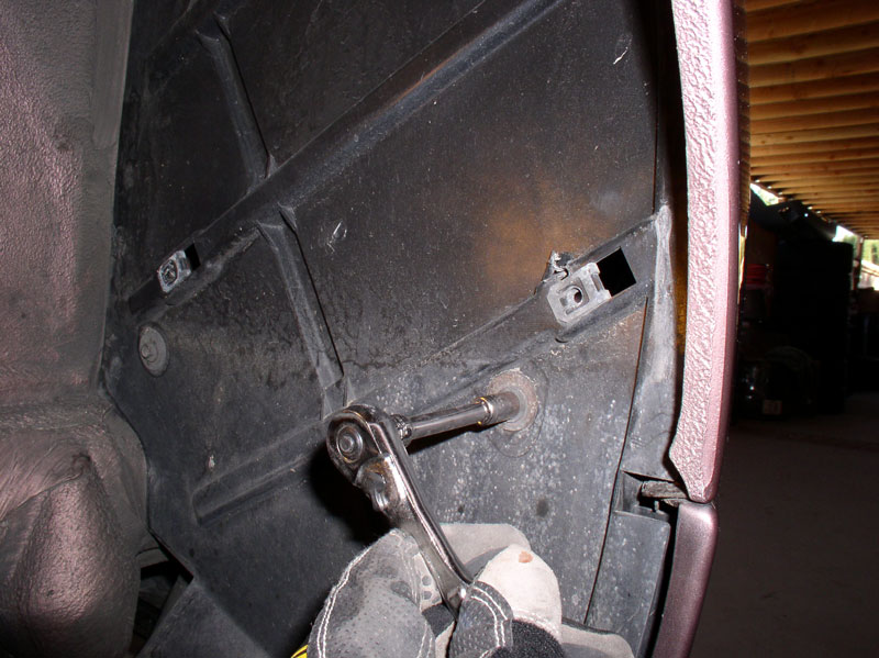
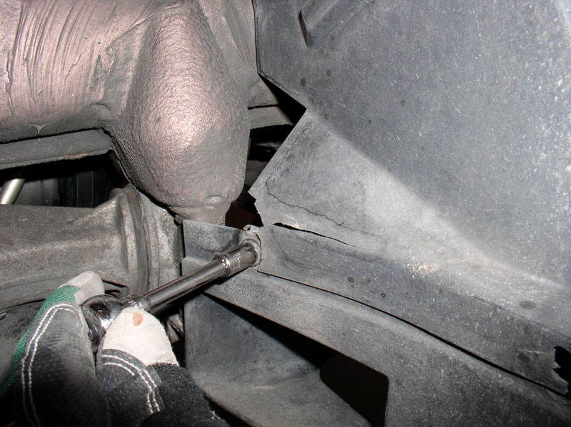
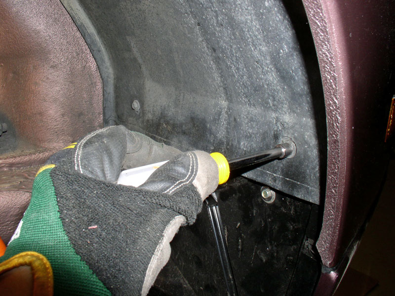
Remove the wheel liners for both wheel wells next. There are two 8mm screws on the rearward side.
There are two 8mm screws at the top of the wheel well and two more at the front of the wheel well.
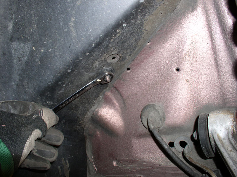
Also remove the one 10mm nut as shown below.
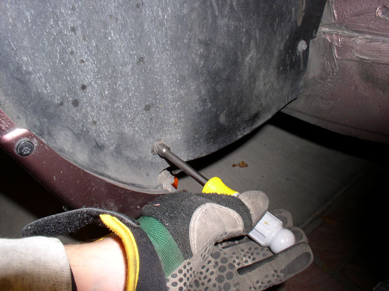
I found it easier to pry the outer edge of the liner out from under the fender lip then maneuvering it out as pictured below.
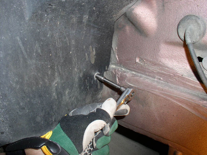
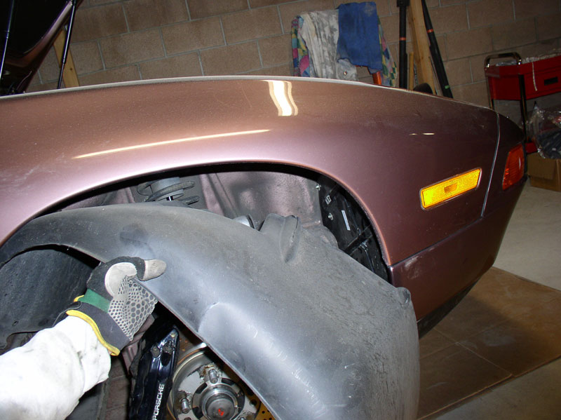
Remove the forward splash shields next. They are attached with 8mm screws as well..
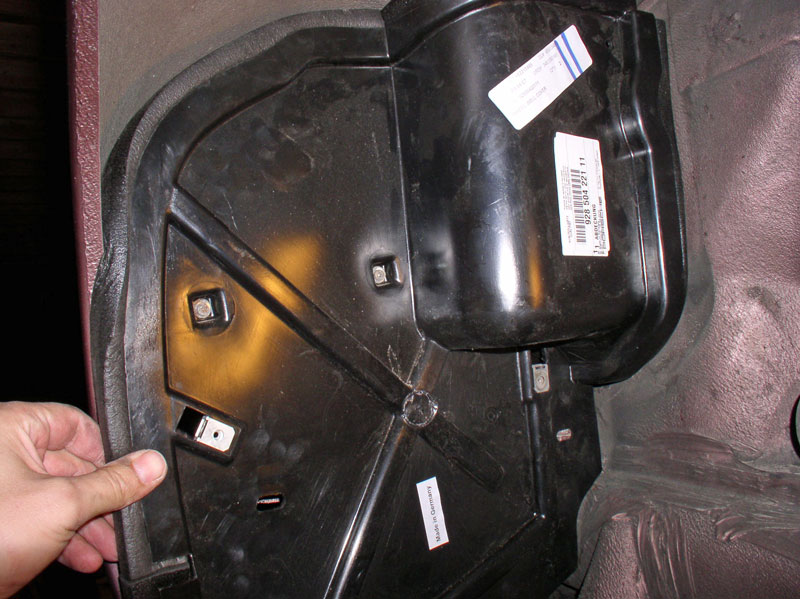
Since Virginia’s splash shields were cracked and broken at the lower edges, I purchased replacement splash shields and new splash shield seals. I believe some people have been able to repair the broken splash shields depending on the extent of the damage. The right (passenger) splash shield is pictured below.
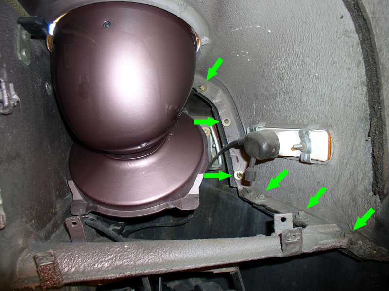
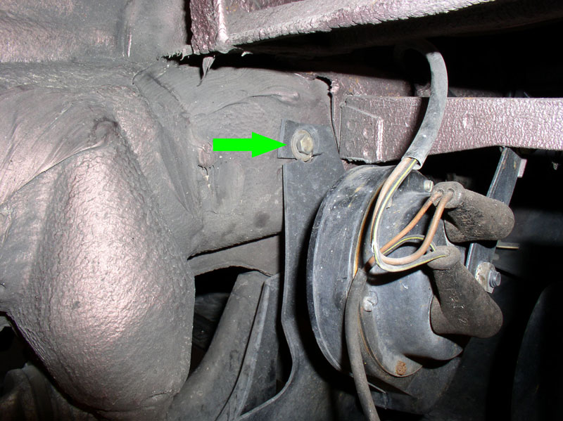
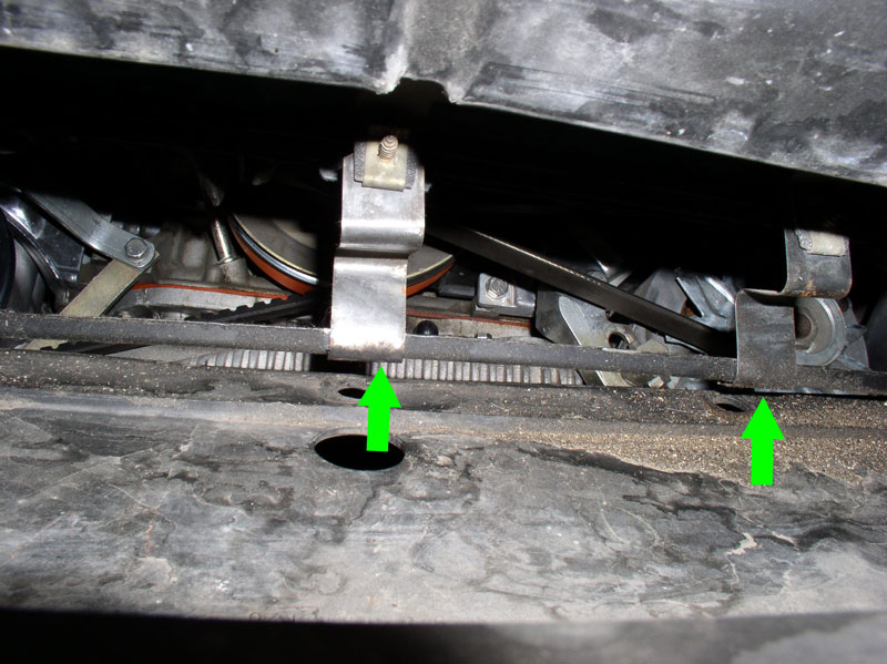
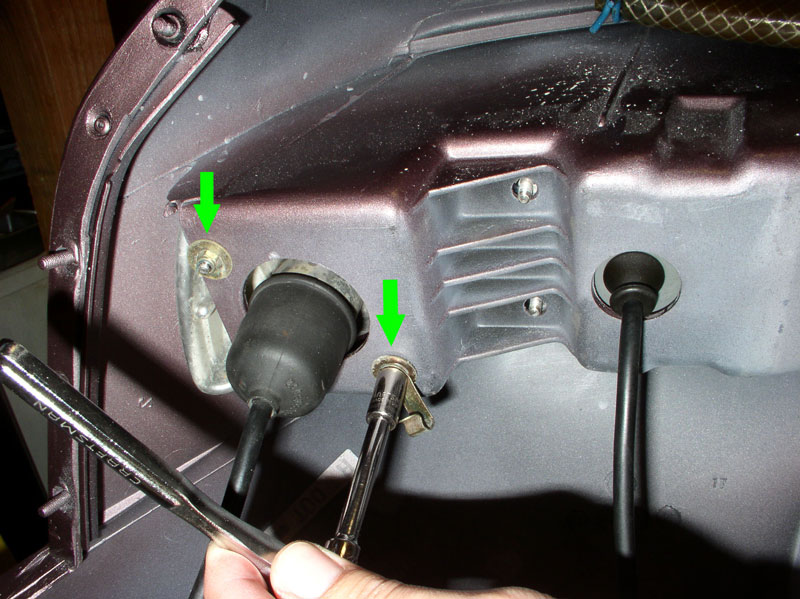
Once you have the splash shield removed, you can get a glimpse of the dark inner workings of the inside fender. The bumper cover is mounted to the fender using eight 8mm nuts/studs as depicted in the pic below by the green arrows. There are two more nuts behind the headlight assembly. You will need to raise the headlight in order to reach those two nuts. I simply turned the headlights on, removed the key from the ignition then turned the headlight switch to “Off” and the headlights will stay up.
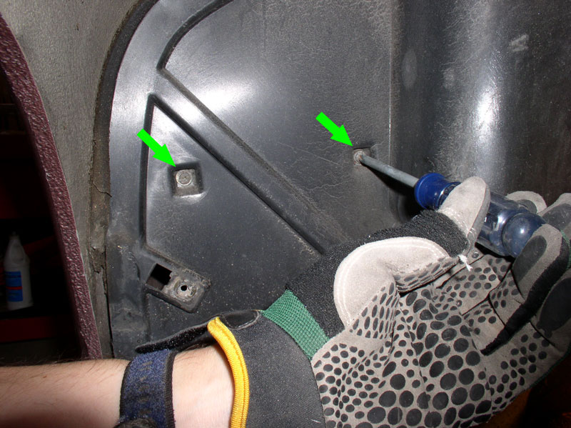
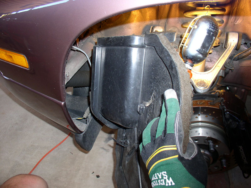
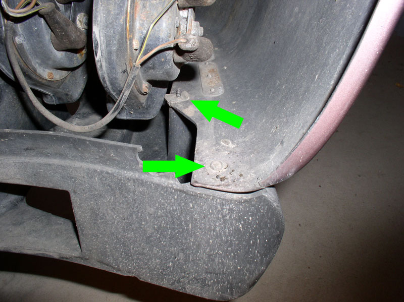
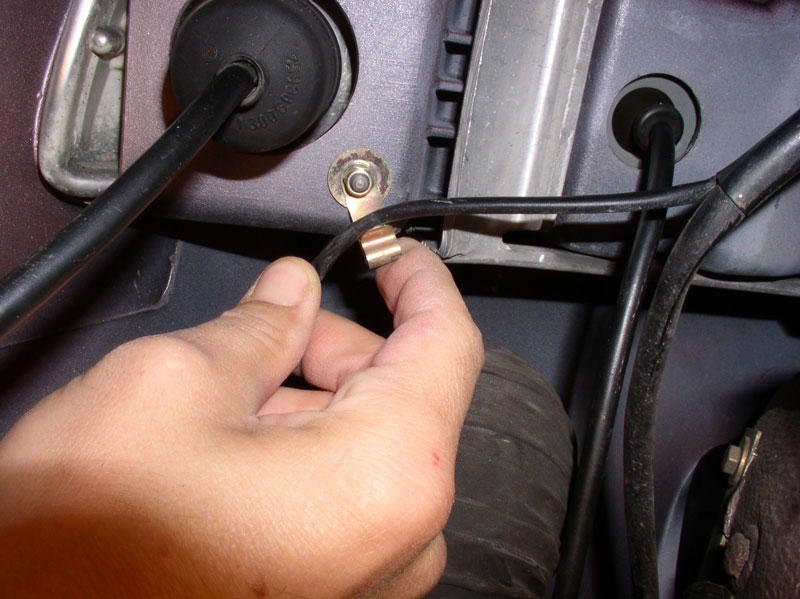
The Left (Driver’s side) splash shield requires an additional step for removal. You will need to remove the outside air temperature sensor and alternator cooling duct clamp from the splash shield. Remove the two Phillips screws as indicated by the green arrows in the picture below.
Rotate the splash shield out enough to expose the outside temperature sensor harness and zip tie as indicated by the green arrow below.
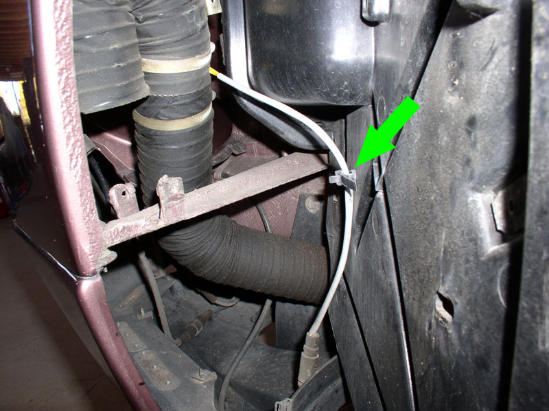
The zip tie is re-usable so no need to snip it with cutters. Remove the harness from the tie and….
….maneuver the splash shield out. You can see the sealing foam in the splash shield has disintegrated. Even if you keep your existing splash shields, replacement foam can be obtained from the 982 parts vendors.
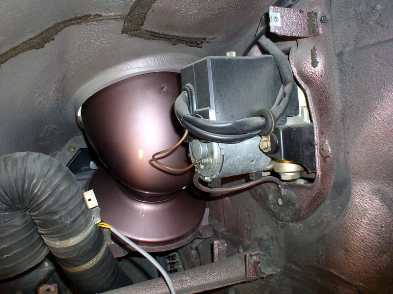
Once the splash shield is removed, you can see the ABS pump exposed. We wont’ be doing anything with the pump….just an interesting sight along the tour.
Continued....
We’ve had Virginia (’87) for a couple of years now and the front bumper cover seemed to be getting noticeably worse as the weeks went by. The front bumper cover had obviously been repaired and repainted at some time earlier well before we purchased the car. You can see the crack below where something was struck. The paint was peeling and there was a depression or warp in the cover just above the left fog lamp assembly as depicted below by the green circle.
We considered having this bumper cover repaired again and repainted but I was not confident the warp could be fully removed. I looked as some refurbished covers and they too did not appear to be perfectly smooth as the cover on Idaho (my baseline for comparison). So we opted to purchase a brand new Porsche bumper cover and have it painted. The brand new cover came primed and upon inspection it was perfectly shaped with no warps or ripples by sight and touch. I did the removal and install of the cover and had a local paint and body shop perform the color matching and painting.
This procedure details the process I used to remove and re-install a new bumper cover. This was my first bumper cover removal and I thought I'd take a picture or two along the way to help other DIYers that may want to try this repair for the first time themselves. It would also apply if you are simply repairing/repainting your existing bumper cover.
WARNING: This is a Newbie-rated procedure and contains step-by-step instructions for the removal and installation process and contains approximately 135 pictures.
PARTS, TOOLS AND PREPARATION
For this job I purchased the following parts:
1. New Bumper cover (928.505.113.20) – refurbished are also available or you can have your original cover repaired.
2. Beading for front bumper (2) (928.505.143.03)
Optional parts that may be considered if you have cracked or broken parts:
1. Front Spoiler (928.505.071.21) I couldn’t get the spoiler for the ’87 MY so the part number here reflects what is available for ’90 and later.
2. Front Spoiler Install kit (928.505.071.21KT) through 928 International
3. Headlight Squirters (928.528.071.02) if yours are cracked or faded.
4. Left Splash Shield (928.504.221.11)
5. Right Splash Shield (928.504.222.11)
6. Splash Shield Seal Left Long (928.504.223.07)
7. Splash Shield Seal Left Top (928.504.223.05)
8. Splash Shield Seal Left Inside (928.504.223.04)
9. Splash Shield Seal Right (928.504.223.08)
10. Splash Shield Seal Left/Right (2) (928.504.223.09)
I used the following Special Tools for the job:
1. Porken’s Lift Bars
2. HF 6-Ton Jack Stands
3. Stanley Blind Riveter (available at Home Depot)
I also used some non-hardening automotive sealant that is to go between the bumper cover and the fender mating surfaces just in front of the front wheels. The picture below is the 3M sealant I used:
The only Preparation I did for the job was researching what options were available for the front bumper cover (new, refurbished, or repair existing), researching and obtaining an estimate of the paint work from an auto body and paint shop, ordering parts, and clearing a suitable workbench area to work on the bumper cover once removed.
REMOVING BUMPER COVER
Start by loosening the front wheel lug nuts, raising the car (I used lift bars and jack stands), and removing the front wheels. Once the car is lifted, you will need to remove the belly pans as the front belly pan is attached to the spoiler and the spoiler will be removed with the bumper cover.
Remove the wheel liners for both wheel wells next. There are two 8mm screws on the rearward side.
There are two 8mm screws at the top of the wheel well and two more at the front of the wheel well.
Also remove the one 10mm nut as shown below.
I found it easier to pry the outer edge of the liner out from under the fender lip then maneuvering it out as pictured below.
Remove the forward splash shields next. They are attached with 8mm screws as well..
Since Virginia’s splash shields were cracked and broken at the lower edges, I purchased replacement splash shields and new splash shield seals. I believe some people have been able to repair the broken splash shields depending on the extent of the damage. The right (passenger) splash shield is pictured below.
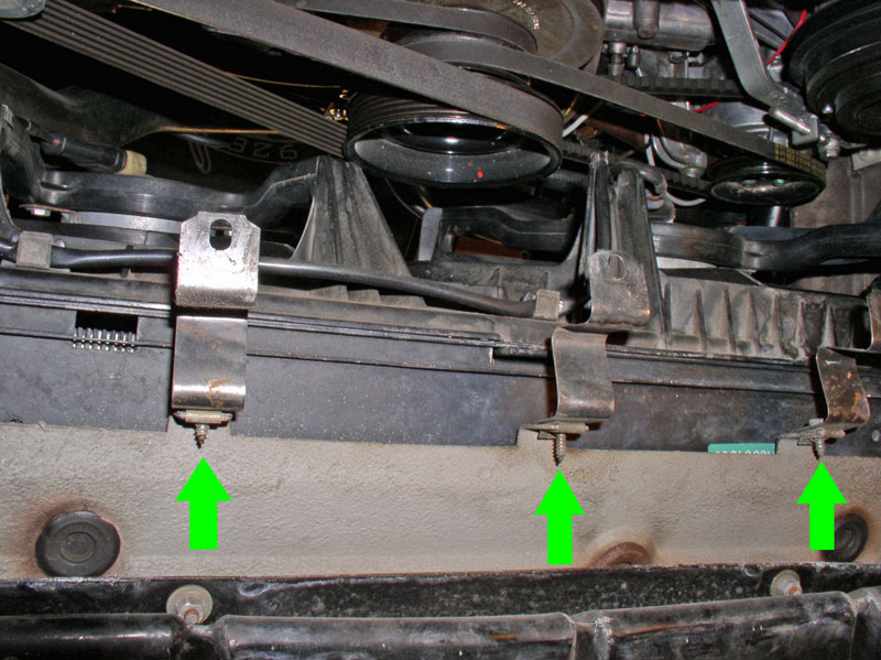
Once you have the splash shield removed, you can get a glimpse of the dark inner workings of the inside fender. The bumper cover is mounted to the fender using eight 8mm nuts/studs as depicted in the pic below by the green arrows. There are two more nuts behind the headlight assembly. You will need to raise the headlight in order to reach those two nuts. I simply turned the headlights on, removed the key from the ignition then turned the headlight switch to “Off” and the headlights will stay up.
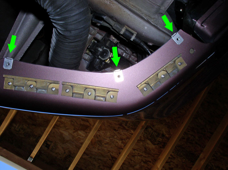
The Left (Driver’s side) splash shield requires an additional step for removal. You will need to remove the outside air temperature sensor and alternator cooling duct clamp from the splash shield. Remove the two Phillips screws as indicated by the green arrows in the picture below.
Rotate the splash shield out enough to expose the outside temperature sensor harness and zip tie as indicated by the green arrow below.
The zip tie is re-usable so no need to snip it with cutters. Remove the harness from the tie and….
….maneuver the splash shield out. You can see the sealing foam in the splash shield has disintegrated. Even if you keep your existing splash shields, replacement foam can be obtained from the 982 parts vendors.
Once the splash shield is removed, you can see the ABS pump exposed. We wont’ be doing anything with the pump….just an interesting sight along the tour.
Continued....
 12-26-2010, 01:05 PM
#2
Rennlist Member
Thread Starter
Join Date: Sep 2007
Location: Ridgecrest, California
Posts: 1,363
Likes: 0
Received 143 Likes
on
28 Posts
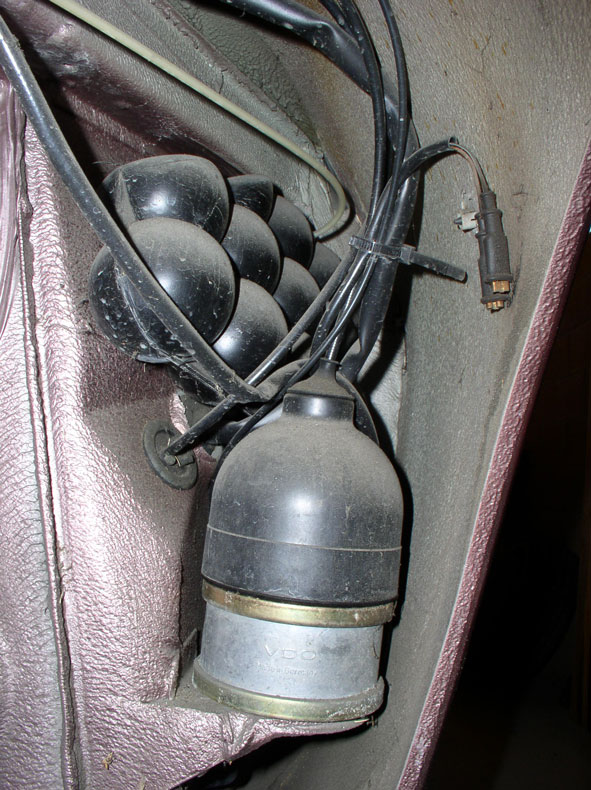
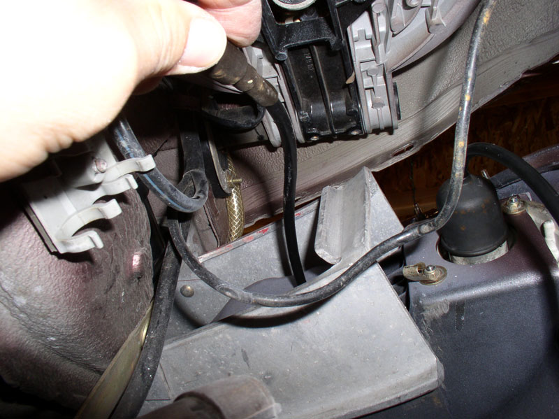
On the rearward side of the wheel well, you will notice the vacuum reservoir and cruise control vacuum actuator. It’s a good idea to check for worn or damaged vacuum lines. These were in good shape.
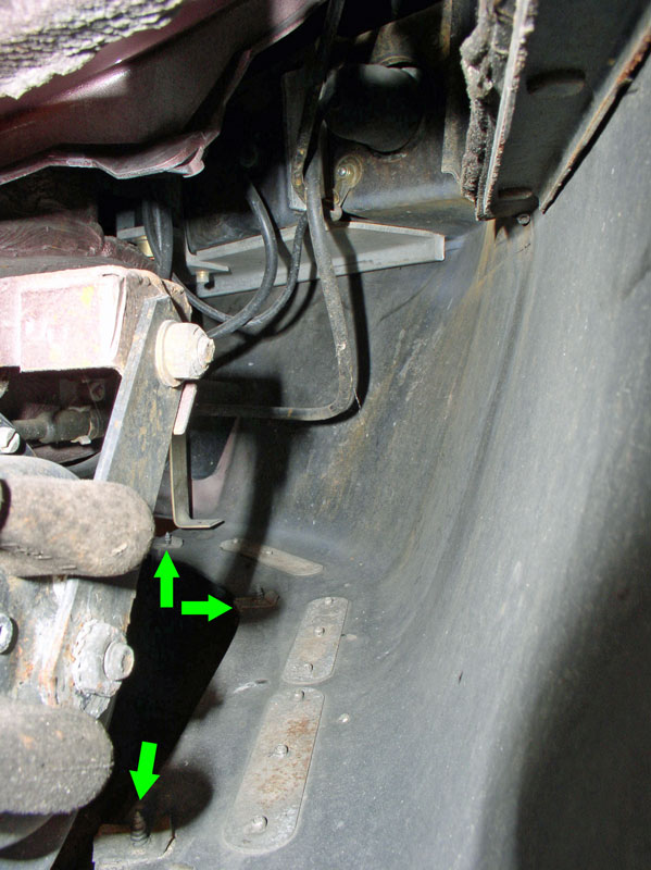
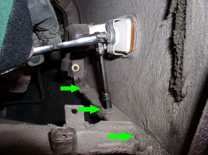
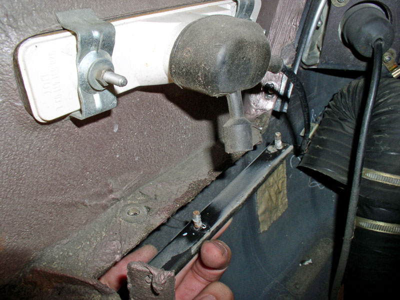
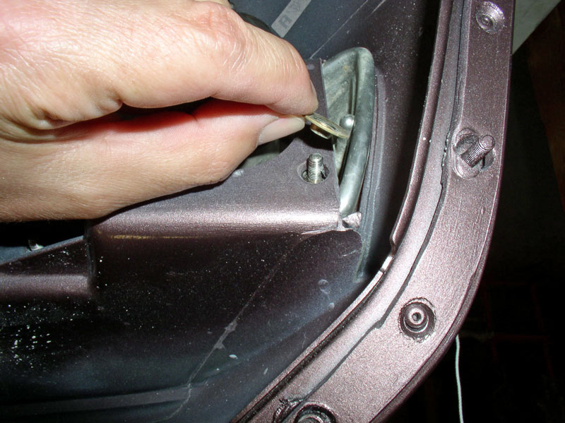
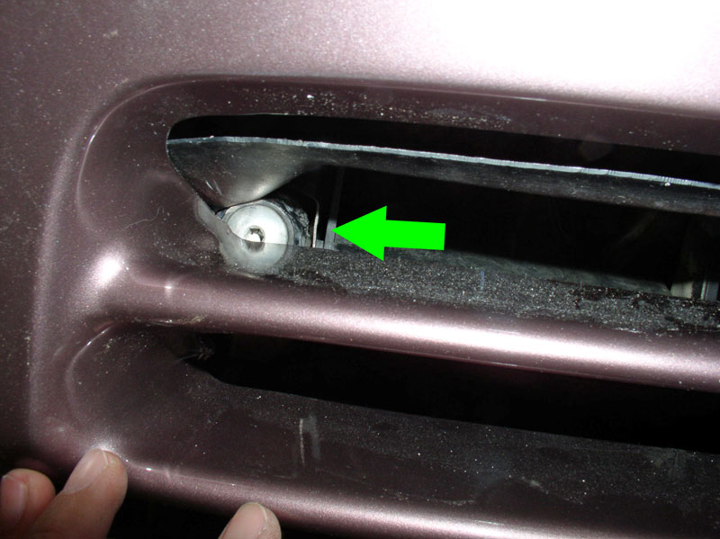
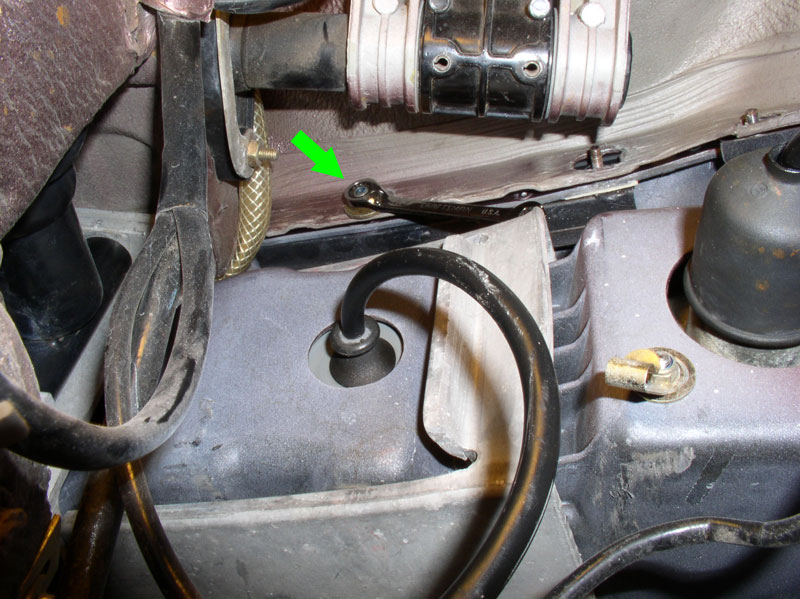
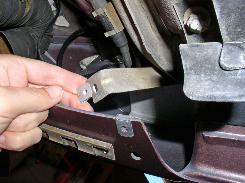
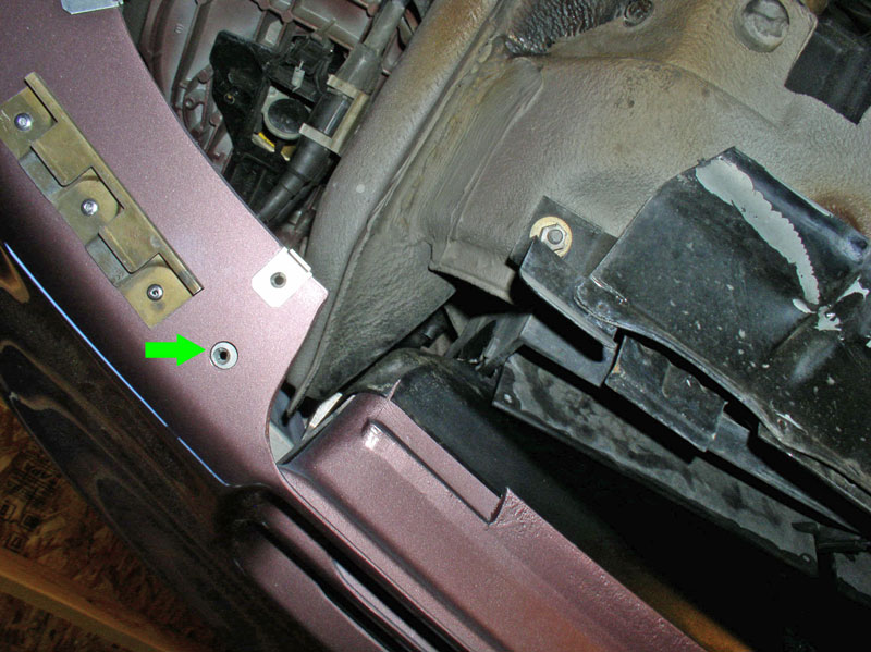
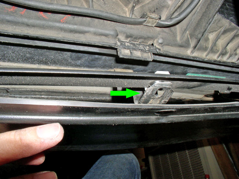
Next, I removed the front spoiler from the bumper cover. Remove the 10mm bolt that attaches the spoiler to the frame member as indicated by the green arrow. Virginia’s tab was cracked as you can see in the pic.
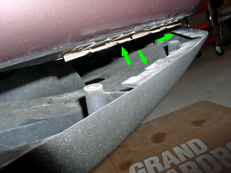
As you can see, the spoiler mounting tab that the splash shield attaches to was also broke which is why I decided to go ahead and replace the spoiler. Remove the 8mm screw (indicated by the lower arrow in the pic below). The upper arrow is one of 3 screws that attach the spoiler to the bumper cover that must be removed from underneath the spoiler.
You can see the three screws protruding through the speed clips in the picture below.
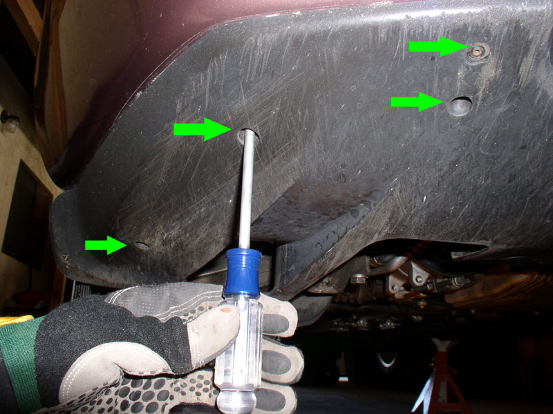
From underneath the spoiler, remove the 3 screws indicated by the green arrows. There is a 4th screw (top green arrow) that is not recessed on the ’87 spoiler (and on the ’88 as well) that must also be removed. The new ‘90+ MY spoiler did not have a hole drilled for this mounting so I’m not sure if the later spoilers will have this screw or not.
From behind the radiator, disengage the spring hangars from the spoiler as indicated by the green arrows.
Remove the spoiler by pulling it out from the fender and forward to clear the hangar clips as shown below. There are clips on the front side of the cover and on the side of the cover.
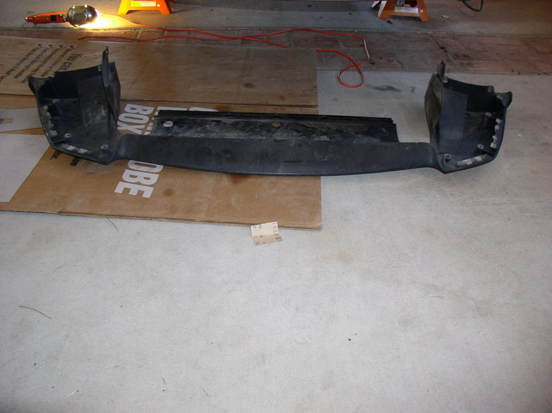
The spoiler should come out and look like the pic below.
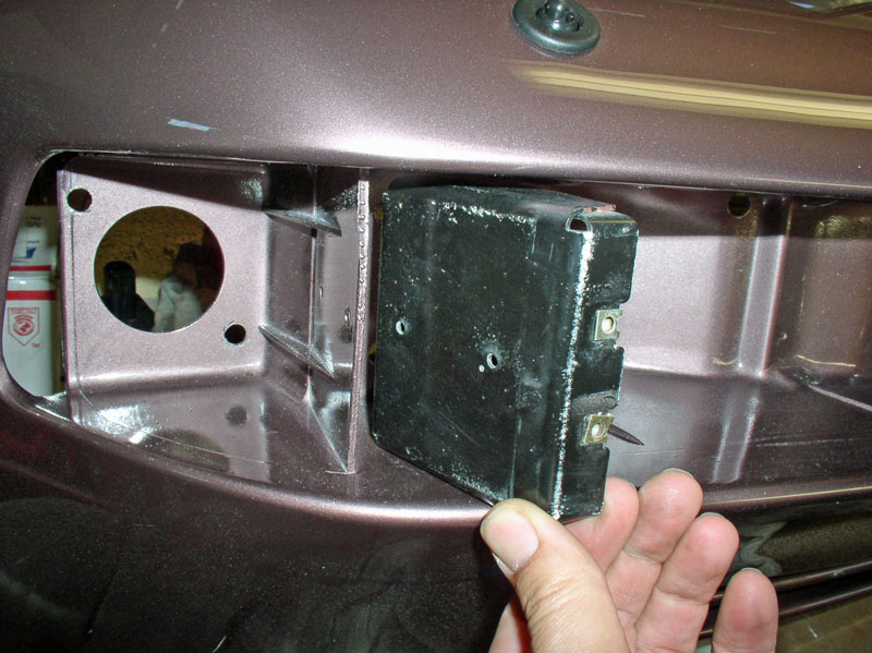
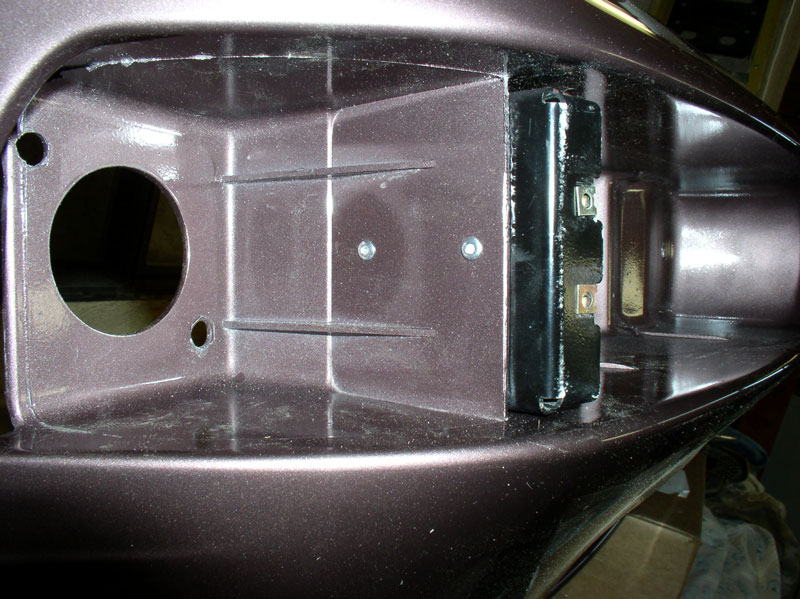
Next, begin taking out the 8mm nuts that secure the bumper cover to the fender. I started with the three nuts on the lower half of the fender as shown.
Once these nuts are removed, the studded back plate should drop out as shown.
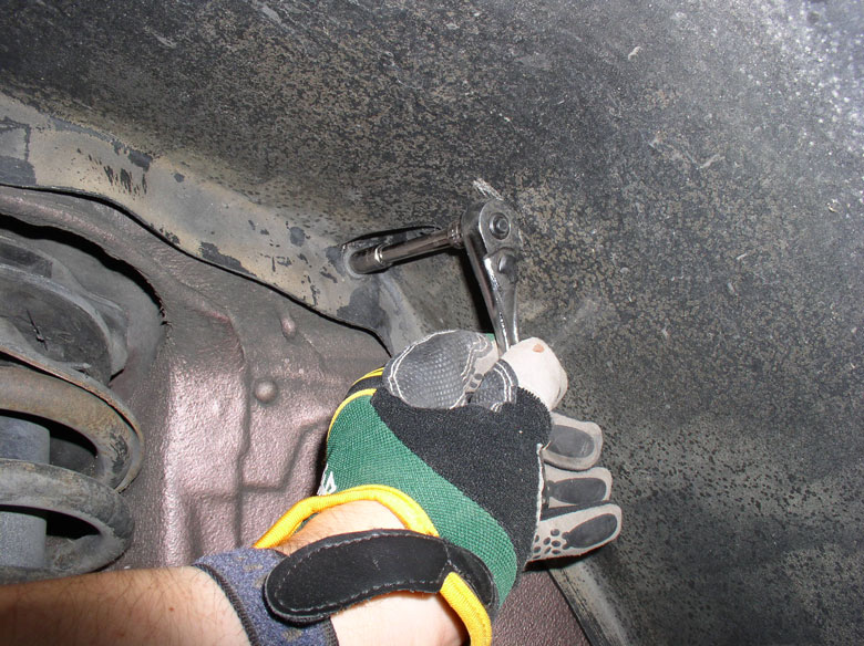
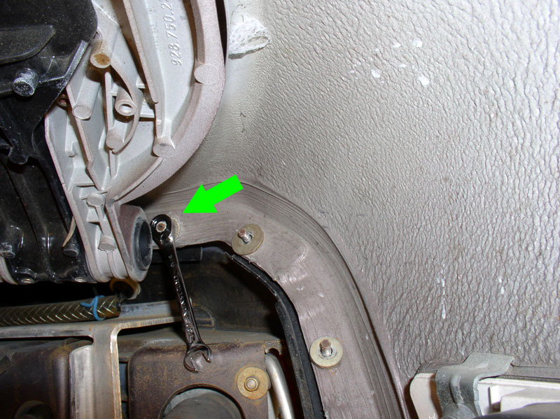
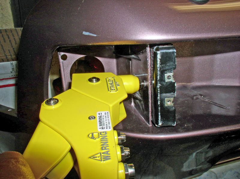
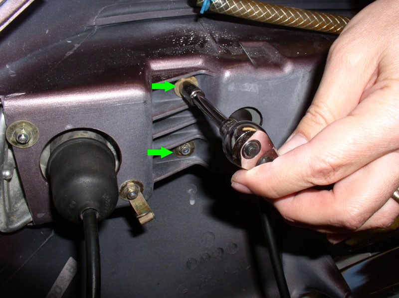
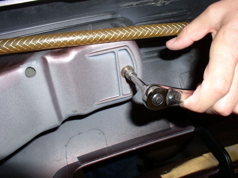
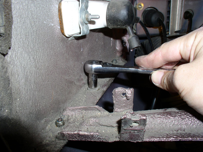
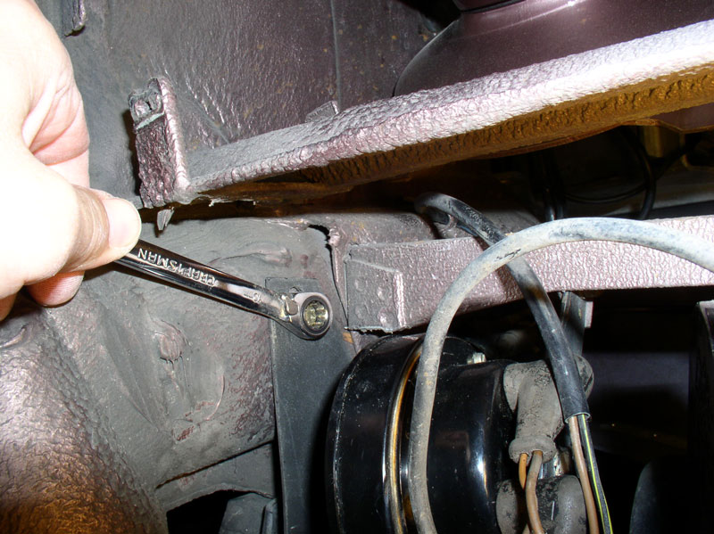
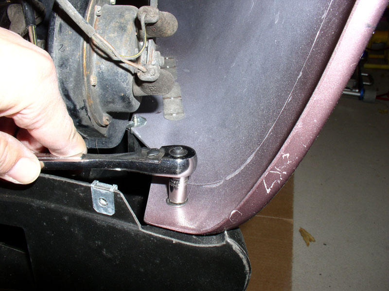
Next remove the 5 remaining 8mm nuts on the forward edge of the fender. There are two difficult nuts to reach behind the headlight when it is raised. I used a gear wrench as depicted below by the arrow.
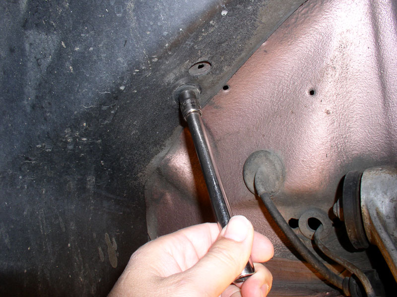
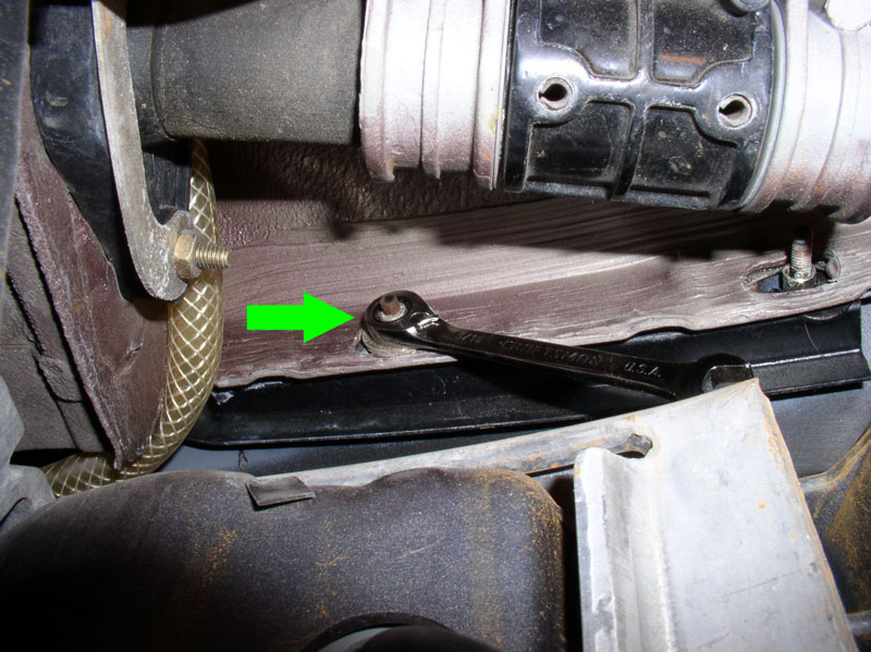
I used the gear wrench again to get at the inner 8mm nut as shown below. Repeat for the other wheel well.
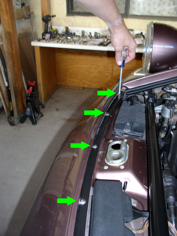
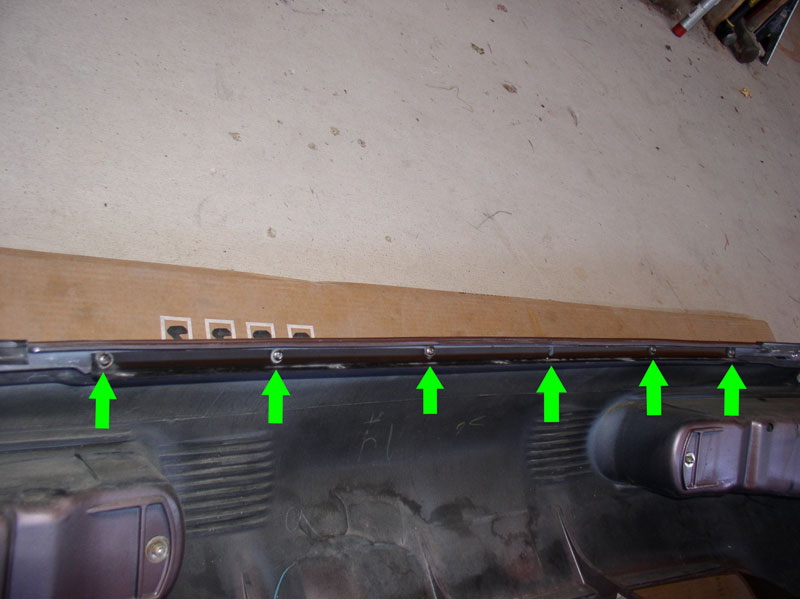
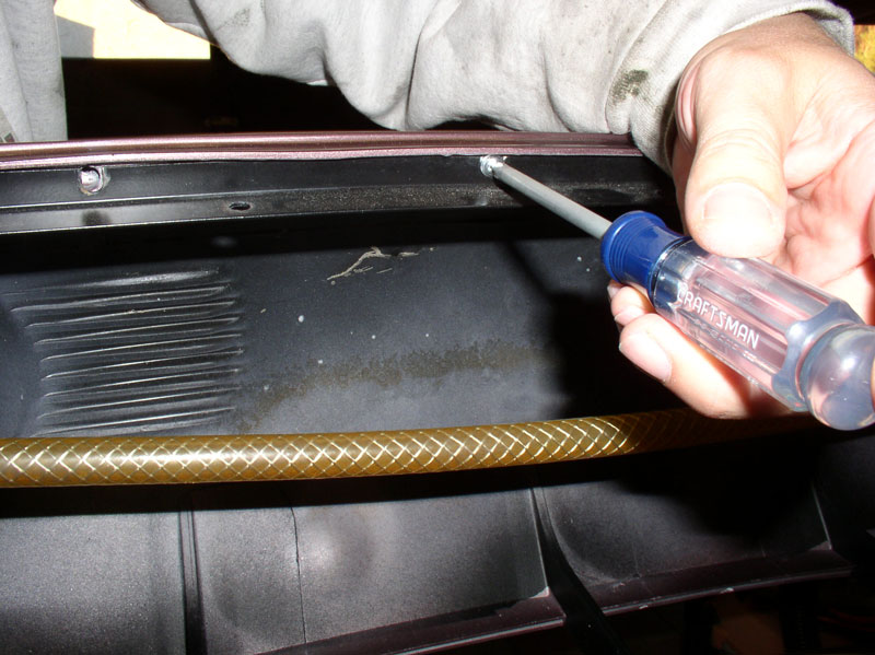
Next, I removed the 5 Phillips head screws that secure the front upper edge of the bumper cover to the body as shown below.
Disconnect he fog lamp wiring harnesses. There are two barrel connectors for each fog lamp/signal assembly. Disconnect both and repeat for the other wheel well.
Also remove the side marker light harness from the clip that’s mounted to the back of the signal indicator as shown. Repeat for the other wheel well.
Continued...
Next, I removed the front spoiler from the bumper cover. Remove the 10mm bolt that attaches the spoiler to the frame member as indicated by the green arrow. Virginia’s tab was cracked as you can see in the pic.
As you can see, the spoiler mounting tab that the splash shield attaches to was also broke which is why I decided to go ahead and replace the spoiler. Remove the 8mm screw (indicated by the lower arrow in the pic below). The upper arrow is one of 3 screws that attach the spoiler to the bumper cover that must be removed from underneath the spoiler.
You can see the three screws protruding through the speed clips in the picture below.
From underneath the spoiler, remove the 3 screws indicated by the green arrows. There is a 4th screw (top green arrow) that is not recessed on the ’87 spoiler (and on the ’88 as well) that must also be removed. The new ‘90+ MY spoiler did not have a hole drilled for this mounting so I’m not sure if the later spoilers will have this screw or not.
From behind the radiator, disengage the spring hangars from the spoiler as indicated by the green arrows.
Remove the spoiler by pulling it out from the fender and forward to clear the hangar clips as shown below. There are clips on the front side of the cover and on the side of the cover.
The spoiler should come out and look like the pic below.
Next, begin taking out the 8mm nuts that secure the bumper cover to the fender. I started with the three nuts on the lower half of the fender as shown.
Once these nuts are removed, the studded back plate should drop out as shown.
Next remove the 5 remaining 8mm nuts on the forward edge of the fender. There are two difficult nuts to reach behind the headlight when it is raised. I used a gear wrench as depicted below by the arrow.
I used the gear wrench again to get at the inner 8mm nut as shown below. Repeat for the other wheel well.
Next, I removed the 5 Phillips head screws that secure the front upper edge of the bumper cover to the body as shown below.
Disconnect he fog lamp wiring harnesses. There are two barrel connectors for each fog lamp/signal assembly. Disconnect both and repeat for the other wheel well.
Also remove the side marker light harness from the clip that’s mounted to the back of the signal indicator as shown. Repeat for the other wheel well.
Continued...
12-26-2010, 01:09 PM
#3
Rennlist Member
Let me be the first to welcome you back, with your amazing writeups! You along with they have been missed. 
Although I have no immediate need for FBCRemoval, I find your threads interesting and entertianing, as I scratch my head in wonder - how do you keep your hands so clean?
Although I have no immediate need for FBCRemoval, I find your threads interesting and entertianing, as I scratch my head in wonder - how do you keep your hands so clean?
12-26-2010, 01:26 PM
#4
Rennlist Member
Thread Starter
Join Date: Sep 2007
Location: Ridgecrest, California
Posts: 1,363
Likes: 0
Received 143 Likes
on
28 Posts
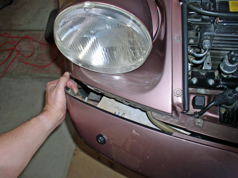
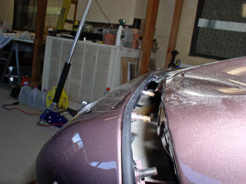
At this point, you should be able to begin pulling the bumper cover forward. I started on one side…..
….and worked the other side free also.
As you are pulling out the bumper cover, note any spacers or shims that may be under the front brace. These help position the bumper cover height so it is aligned with the hood height.
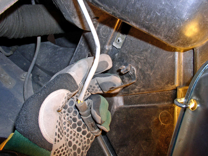
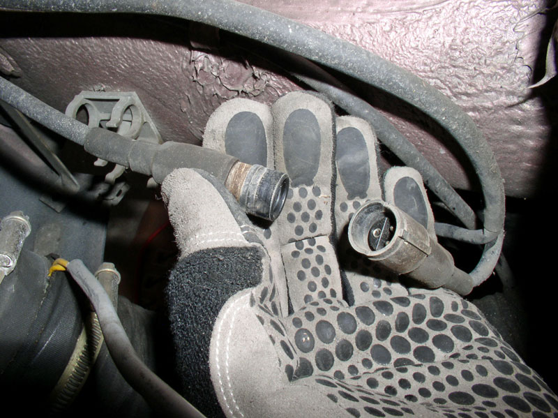
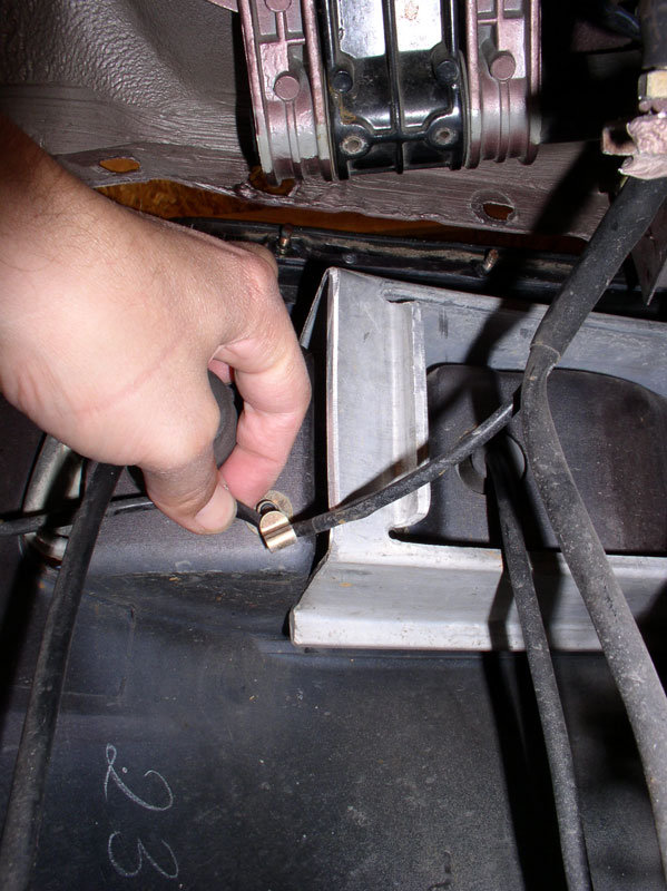
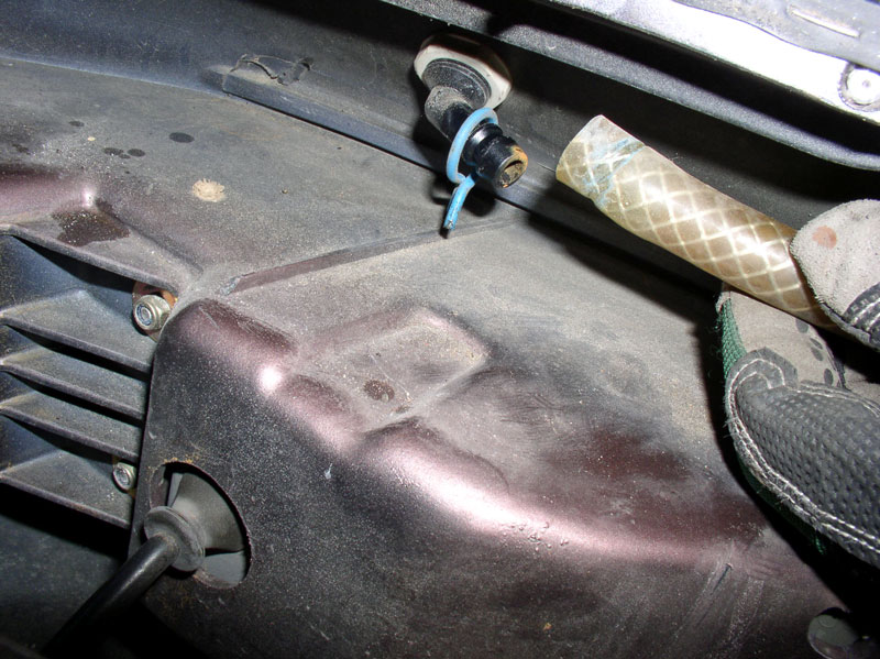
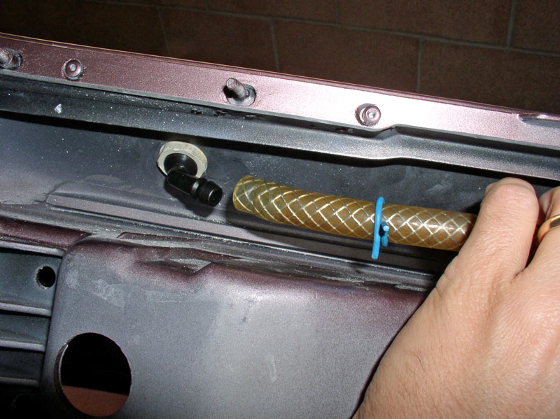
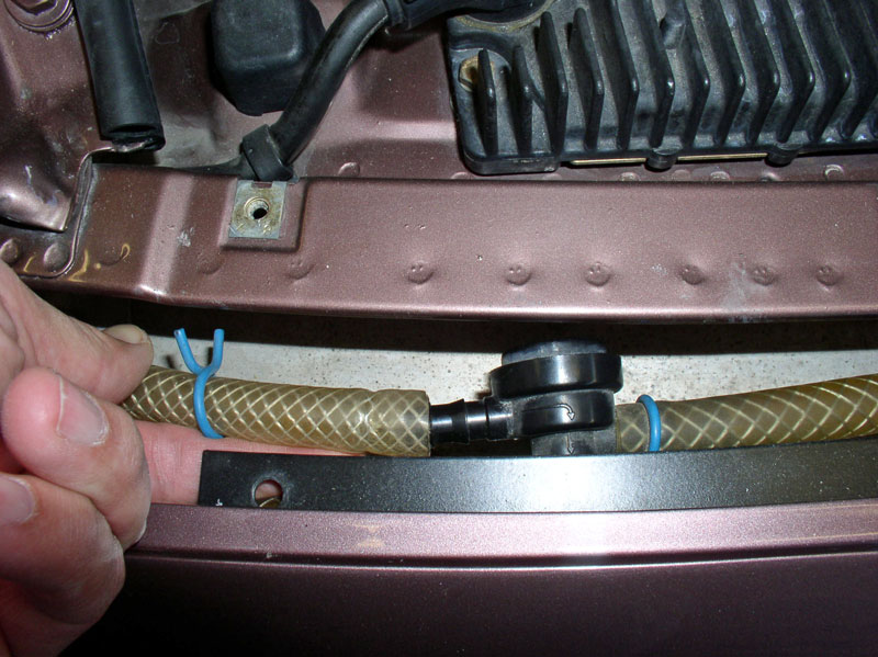
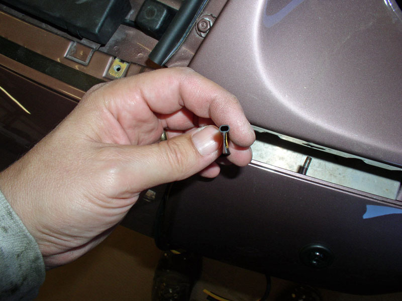
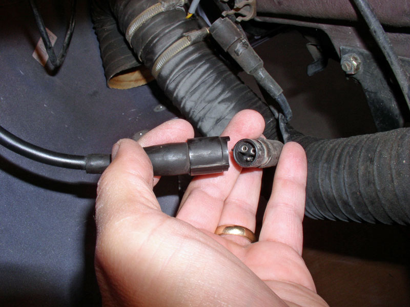
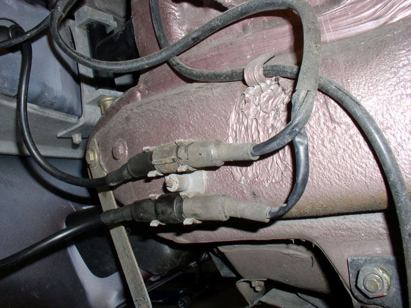
Before removing the bumper cover from the car, you will need to disconnect the headlight squirter supply lines. You can either disconnect the hose at each squirter or you can disconnect the hose at the connection before it is split to the left and right squirters.
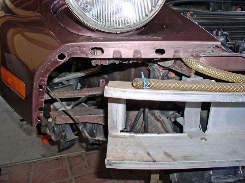
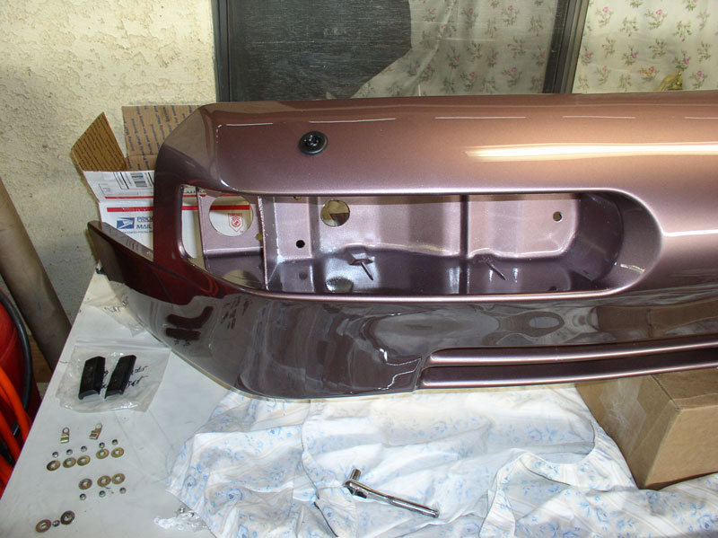
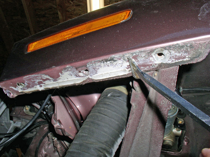
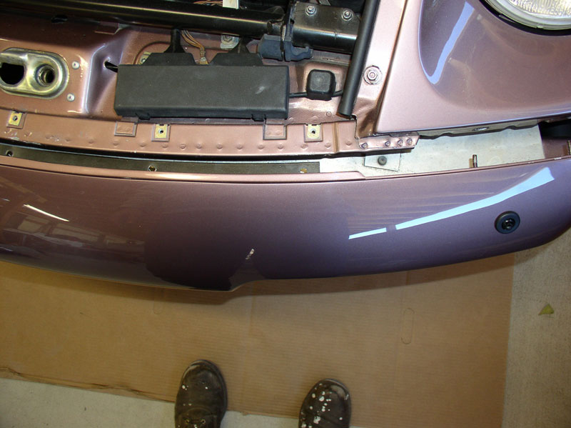
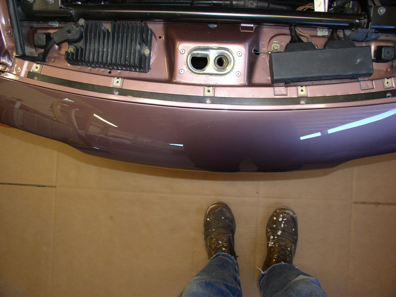
Continue pulling the bumper cover out until it is free and set it aside. I carefully monitored the cover as I was pulling it away to make sure it was not hung up on something. Once the cover is off, you can see the actual bumper. Yours will probably not have a nice dent in it like this one, though. I decided to replace the bumper as well with a nice used one from 928 Intl during their ˝ price sale.
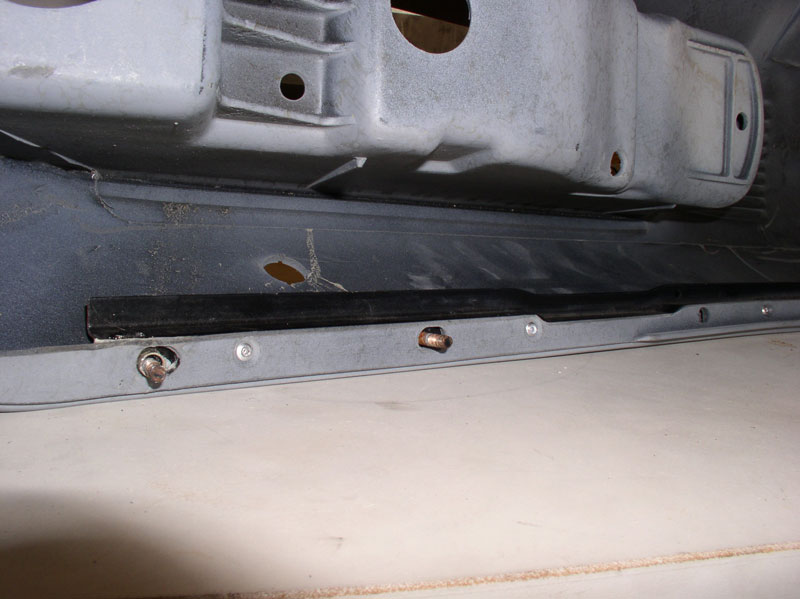
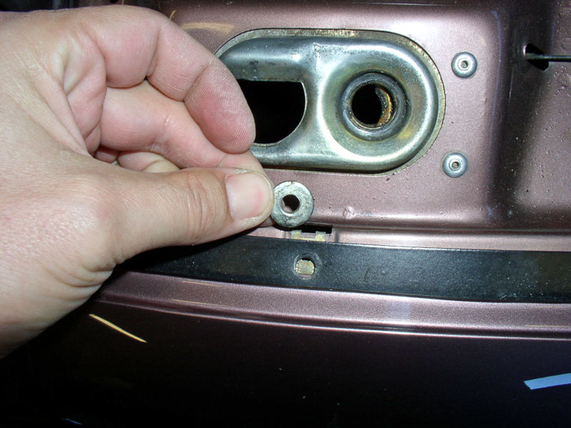
For inquiring minds, you can observe the mounting holes for the bumper cover on the forward edge of the fender seen in the pic below. The holes are oversized and allow for some movement of the bumper cover for alignment purposes.
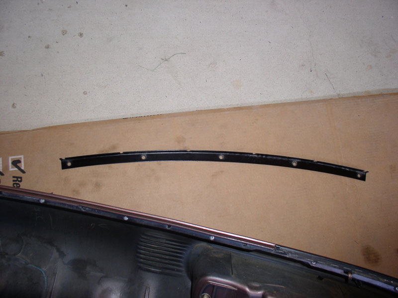
Next, I began the work of striping the bumper cover of lights and hardware that would be transferred to the new bumper cover. I started with removing the six Phillips screws that secure the curved “L” shaped bracket on the forward edge of the cover.
The “L” shaped bracket looks like the pic below when removed.
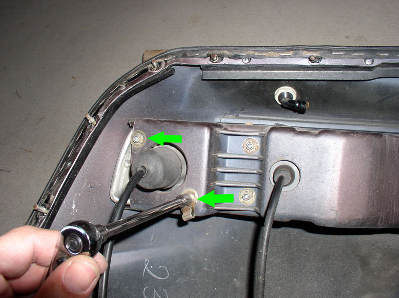
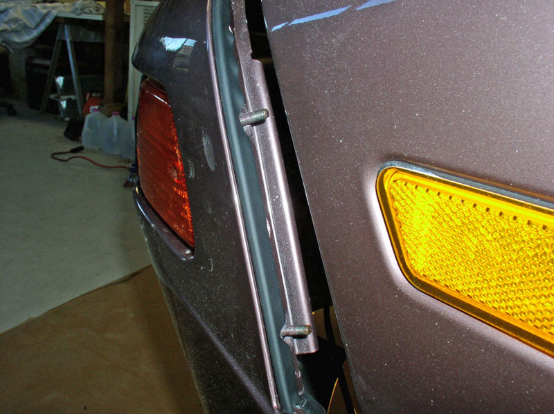
I removed the light assemblies next. Remove the two 8mm nuts that secure the signal indicator. Note the side marker light harness clip is attached to the lower stud as seen below.
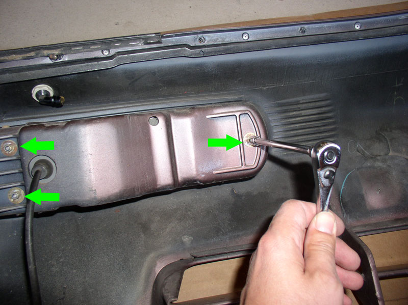
Remove the three 8mm nuts that secure the fog lamp assembly as shown below.
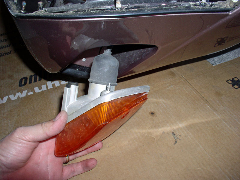
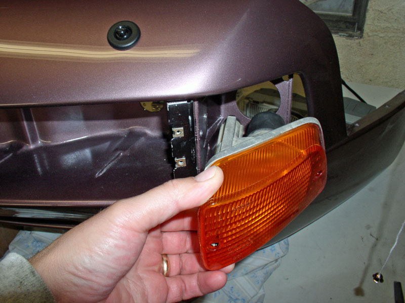
Remove the signal indicator.
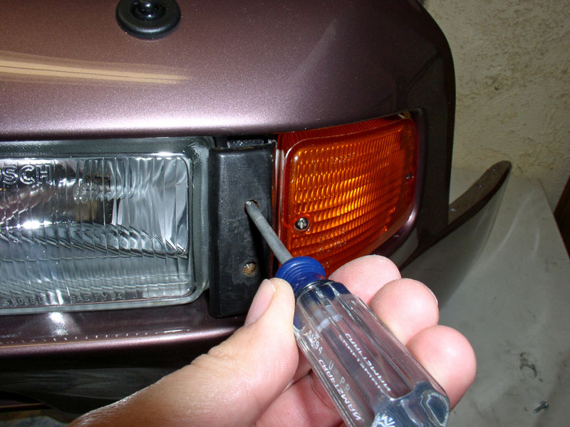
Remove the two Phillips screws that hold the flog lamp mounting cover in place. The two screws are visible on the early ’87 MY but later S4’s have a nice plastic cover plate that hides the two screws. If you have a later S4, you will need to remove this plastic cover by carefully prying the edge up with a small screwdriver. THANKS, Tom (Tom. M) for the tip!.
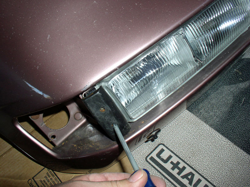
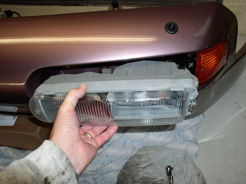
You can gently pry the fog lamp assembly out from the bumper cover with a screwdriver as shown….
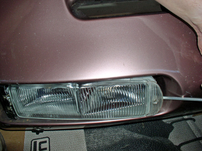
….and remove the assembly.

From underneath the bumper cover, remove the three speed clips from each side as shown in the pic below.
Continued....
….and worked the other side free also.
As you are pulling out the bumper cover, note any spacers or shims that may be under the front brace. These help position the bumper cover height so it is aligned with the hood height.
Before removing the bumper cover from the car, you will need to disconnect the headlight squirter supply lines. You can either disconnect the hose at each squirter or you can disconnect the hose at the connection before it is split to the left and right squirters.
Continue pulling the bumper cover out until it is free and set it aside. I carefully monitored the cover as I was pulling it away to make sure it was not hung up on something. Once the cover is off, you can see the actual bumper. Yours will probably not have a nice dent in it like this one, though. I decided to replace the bumper as well with a nice used one from 928 Intl during their ˝ price sale.
For inquiring minds, you can observe the mounting holes for the bumper cover on the forward edge of the fender seen in the pic below. The holes are oversized and allow for some movement of the bumper cover for alignment purposes.
Next, I began the work of striping the bumper cover of lights and hardware that would be transferred to the new bumper cover. I started with removing the six Phillips screws that secure the curved “L” shaped bracket on the forward edge of the cover.
The “L” shaped bracket looks like the pic below when removed.
I removed the light assemblies next. Remove the two 8mm nuts that secure the signal indicator. Note the side marker light harness clip is attached to the lower stud as seen below.
Remove the three 8mm nuts that secure the fog lamp assembly as shown below.
Remove the signal indicator.
Remove the two Phillips screws that hold the flog lamp mounting cover in place. The two screws are visible on the early ’87 MY but later S4’s have a nice plastic cover plate that hides the two screws. If you have a later S4, you will need to remove this plastic cover by carefully prying the edge up with a small screwdriver. THANKS, Tom (Tom. M) for the tip!.
You can gently pry the fog lamp assembly out from the bumper cover with a screwdriver as shown….
….and remove the assembly.
From underneath the bumper cover, remove the three speed clips from each side as shown in the pic below.
Continued....
Last edited by Dwayne; 12-27-2010 at 10:50 AM.
12-26-2010, 01:35 PM
#5
Rennlist Member
Thread Starter
Join Date: Sep 2007
Location: Ridgecrest, California
Posts: 1,363
Likes: 0
Received 143 Likes
on
28 Posts
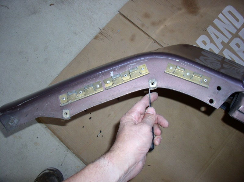
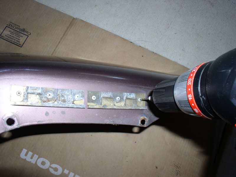
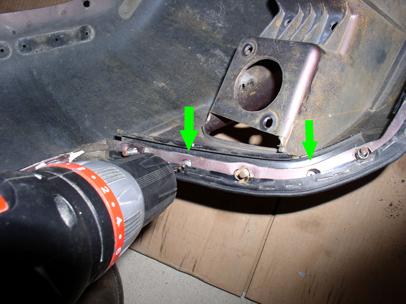
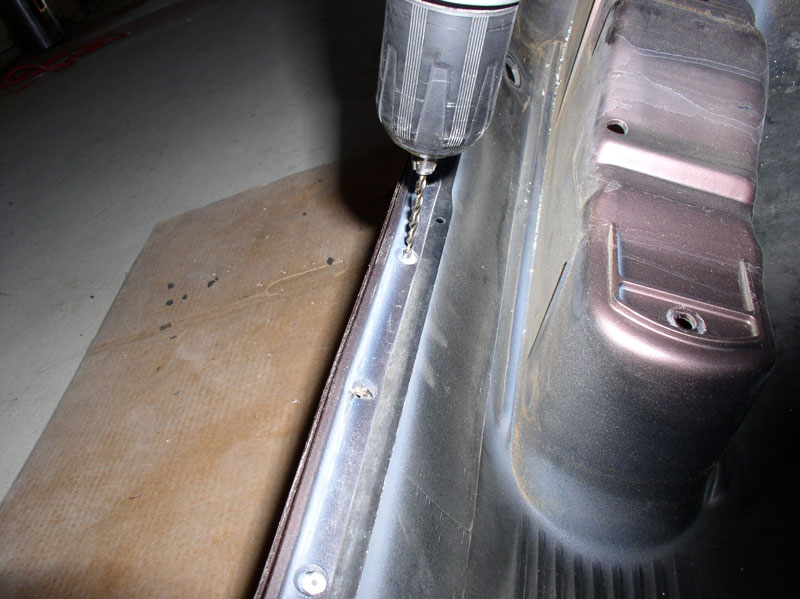
Use a small drill bit to drill out the rivets that secure the spoiler mounting clips to the bumper cover. The drill bit should be no larger than 1/8" since that's the size of the new rivets we'll be installing later on. On the opposite side of the bumper cover, there is a backing plate mated to each mounting clip. Both the mounting clips and backing plates are reusable.
Also drill out the two rivets that secure the fog lamp assembly mounting bracket to the bumper cover as shown below.
And remove the bracket.
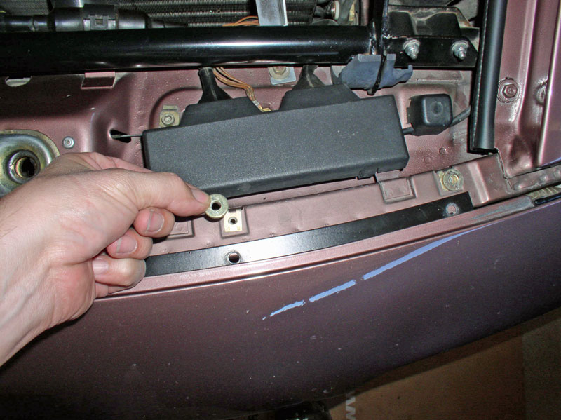
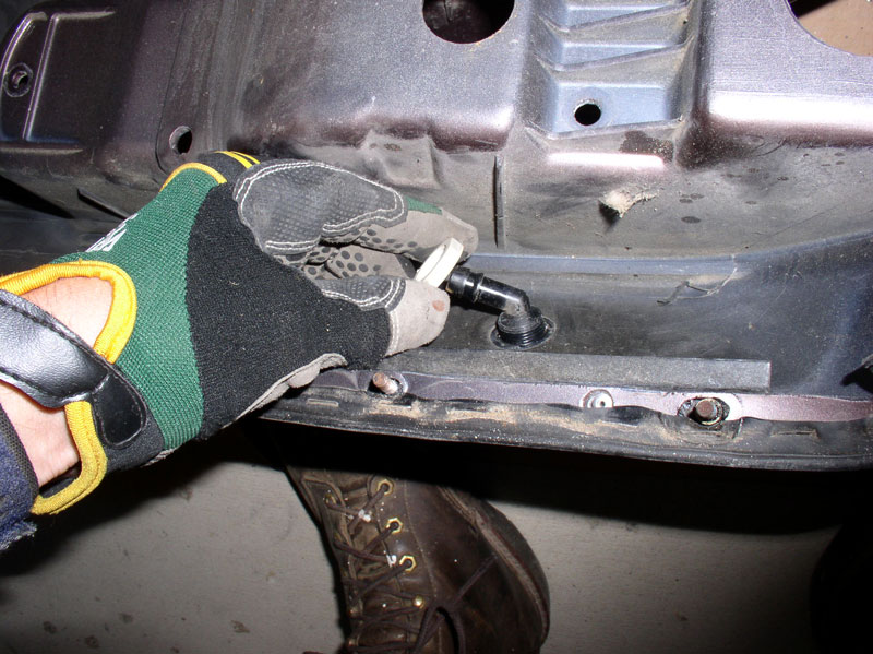
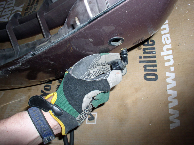
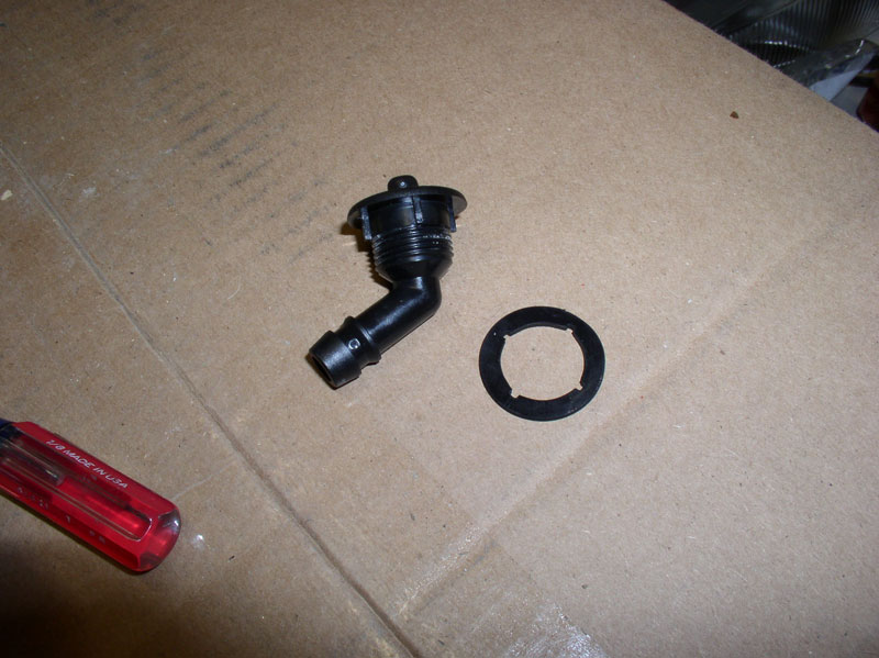
Remove the 24mm plastic headlight squirter nut from the backside of the bumper cover as shown below.
Remove the headlight squirter from the front of the cover as shown below. You will notice the squirter has 4 tabs that mate up with cutouts in the bumper cover.
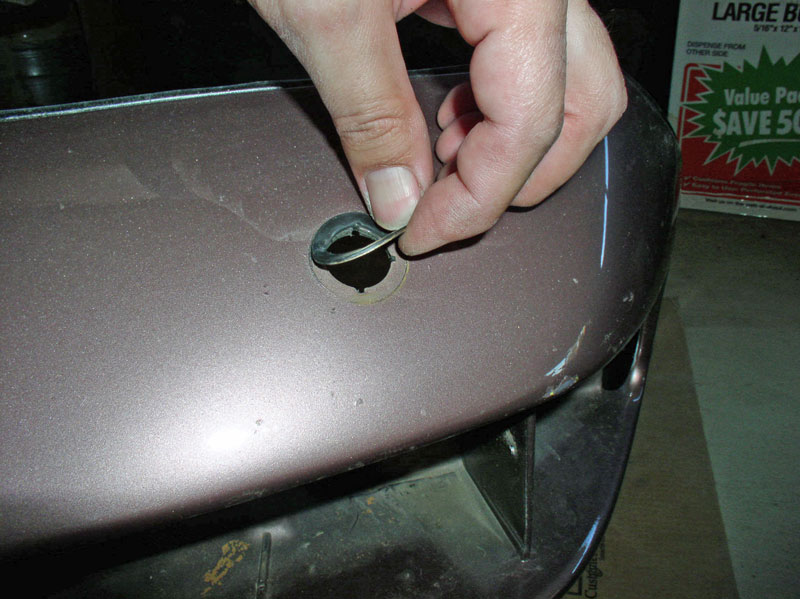
Peel away the rubber gasket underneath the headlight squirter. These were still in great shape. If yours are cracked or split, you may want to replace them.
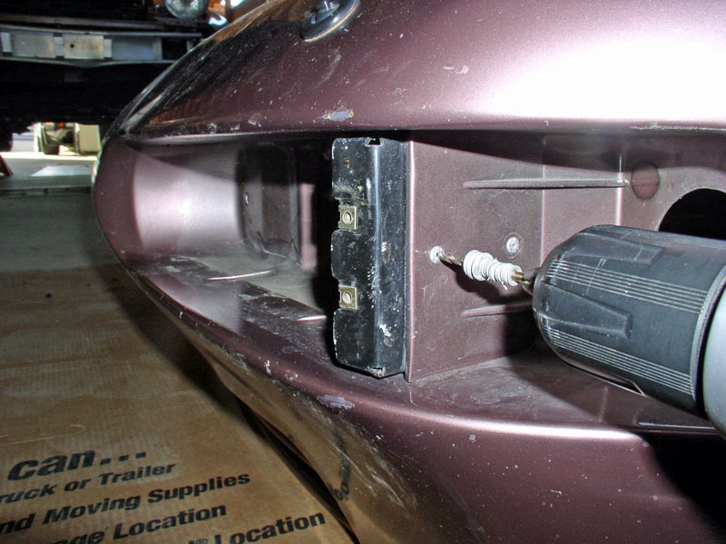
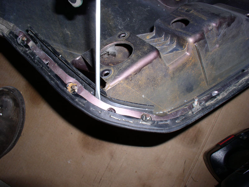
Drill out the two rivets that secure the side studded back plate
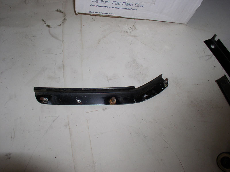
I used a screwdriver to carefully pry the side studded back plate from the bumper cover.
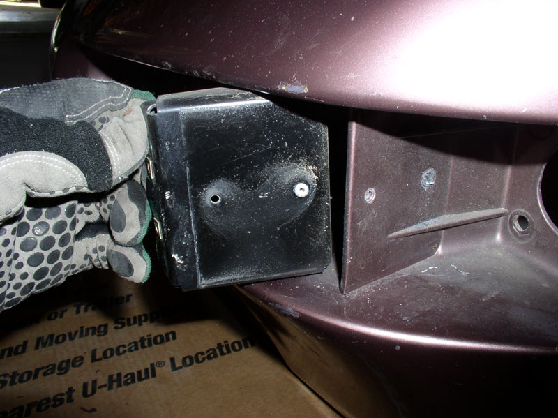
When removed the plate looks like the pic below. Repeat for the other side of the bumper cover.
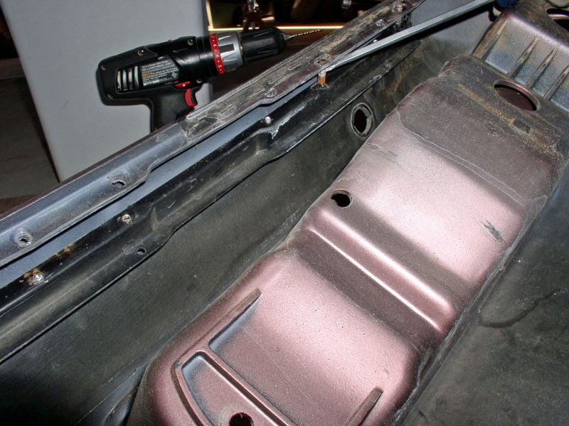
Drill out the rivets for the center top reinforcement bar.
I used a screwdriver again to carefully pry the top reinforcement bar from the bumper cover.
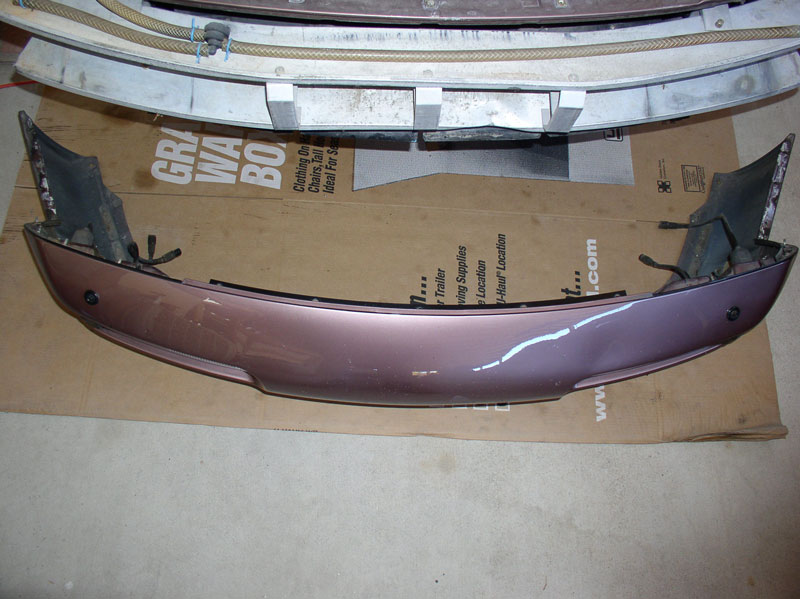
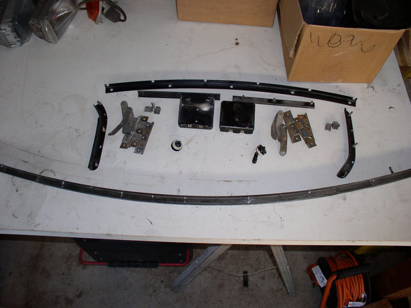
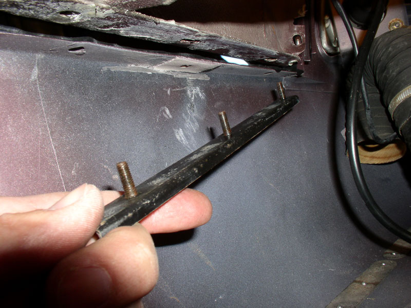
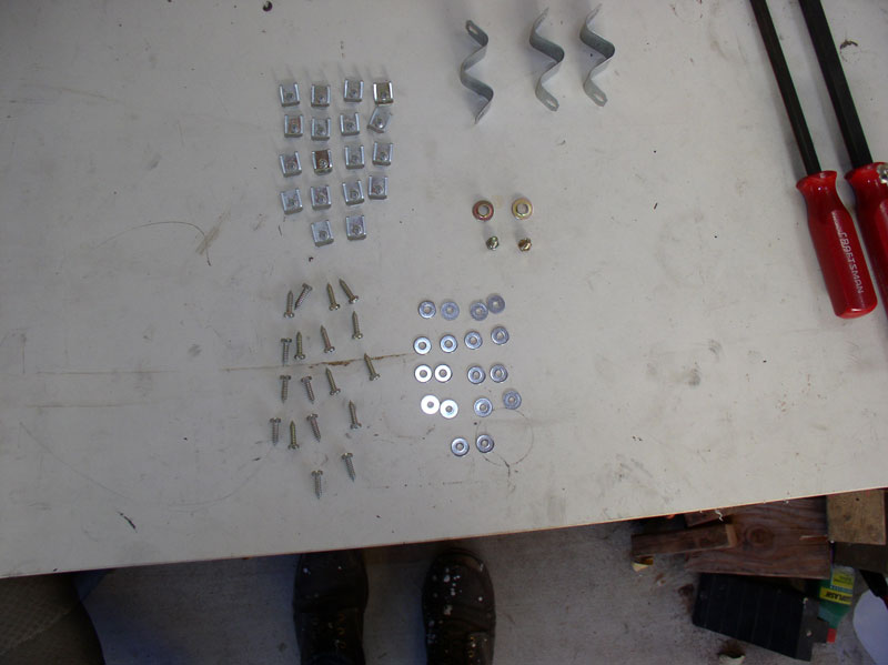
Once removed, the long top reinforcement bar looks like the pic below (bottom). Also pictured is all the other hardware and parts removed from the bumper cover.
Continued....
Also drill out the two rivets that secure the fog lamp assembly mounting bracket to the bumper cover as shown below.
And remove the bracket.
Remove the 24mm plastic headlight squirter nut from the backside of the bumper cover as shown below.
Remove the headlight squirter from the front of the cover as shown below. You will notice the squirter has 4 tabs that mate up with cutouts in the bumper cover.
Peel away the rubber gasket underneath the headlight squirter. These were still in great shape. If yours are cracked or split, you may want to replace them.
Drill out the two rivets that secure the side studded back plate
I used a screwdriver to carefully pry the side studded back plate from the bumper cover.
When removed the plate looks like the pic below. Repeat for the other side of the bumper cover.
Drill out the rivets for the center top reinforcement bar.
I used a screwdriver again to carefully pry the top reinforcement bar from the bumper cover.
Once removed, the long top reinforcement bar looks like the pic below (bottom). Also pictured is all the other hardware and parts removed from the bumper cover.
Continued....
12-26-2010, 01:49 PM
#6
Rennlist Member
Nice write-up! What type of rivets do you plan on installing? I have a small hand-rivet tool, but have never used it and I am wondering if it is suitable for such an application. Also can the threaded mounting studs that are fitted to the steel plates on the bumper cover be replaced? Several of mine are severely rusted/snapped off.
Trending Topics
12-26-2010, 01:54 PM
#8
Rennlist Member
Thread Starter
Join Date: Sep 2007
Location: Ridgecrest, California
Posts: 1,363
Likes: 0
Received 143 Likes
on
28 Posts
Now I was ready to prepare the new bumper cover for installation. If you are simply re-installing your existing bumper cover after it’s been repaired or repainted, you may not need to do a test fit before final mounting. In my case, I was installing a brand new bumper and I wanted to test fit the cover on the car BEFORE it was painted just in case there were any minor modifications needed before taking the cover to the paint shop. I also wanted to have the primed cover on the car when I took it to the paint shop so they could assess if there were any minor mods needed for the fit before painting.
If you go this route, you don’t need to fully install the cover. I just mounted the cover by attaching the sixteen 8mm studs/nuts that attach the cover to the bumper (8 on each side) and I installed the front reinforcement bar and adjusted the height of the cover. I did not install the rubber beading or the spoiler or wiring or anything else. That way, the paint shop could easily remove the cover by taking off the 8mm nuts and front reinforcement bar after making any adjustments that may be necessary. In addition, the shop needed to keep the car for a couple of hours to do the paint matching.
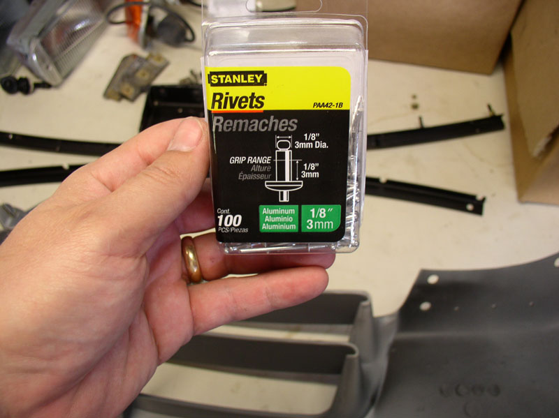
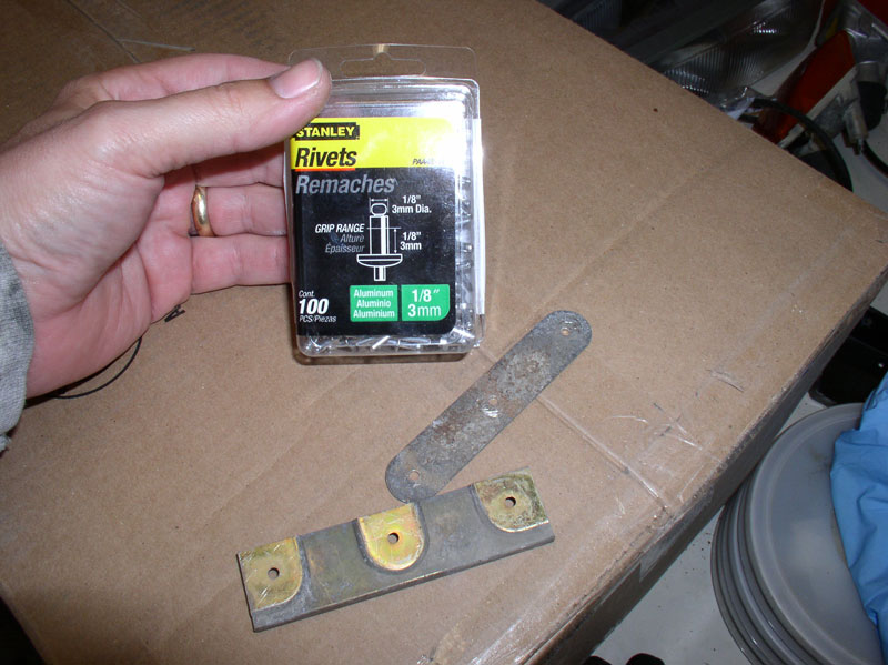
My next step was to re-install the studded back plates onto the bumper cover, I used 1/8” or 3mm diameter rivets in the 1/8” lengths as pictured below. These worked very well for all the mounting points except where there were reinforcement pads on the mounting holes. In these cases, I used longer rivets but still 3mm diameter.
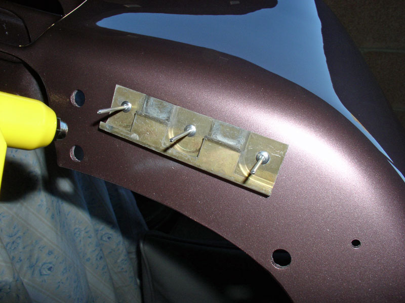
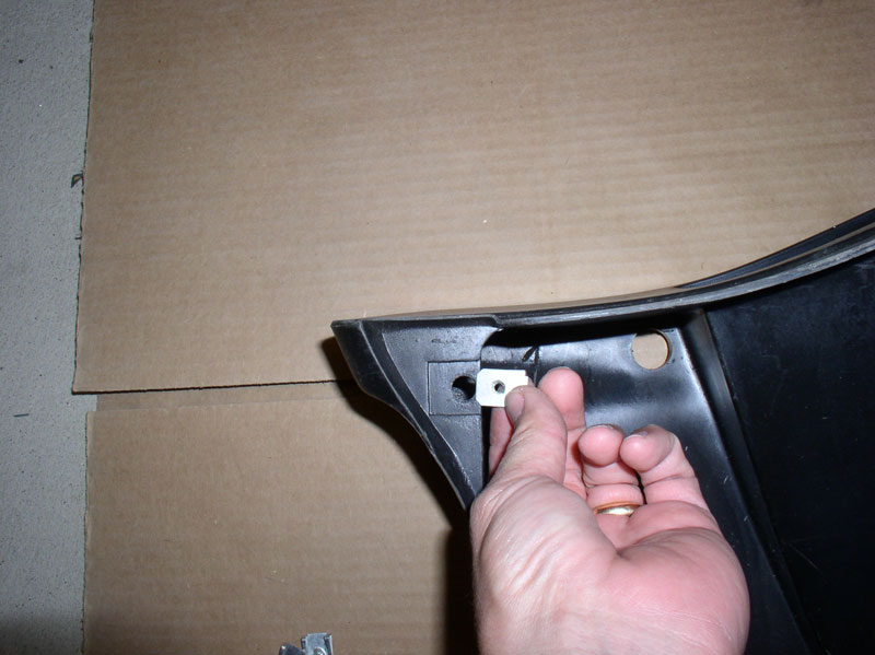
First, I attached the side forward facing plates pictured below. I used small “C” clamps at first but found they were not really necessary.
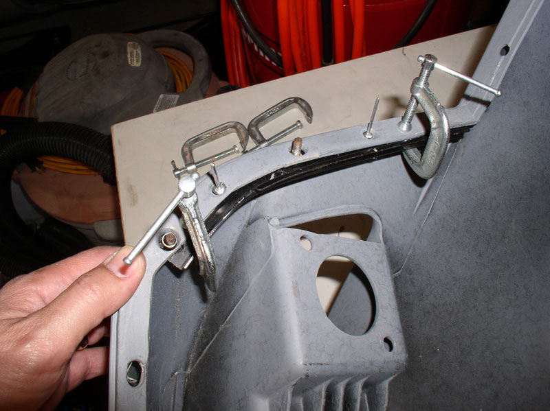
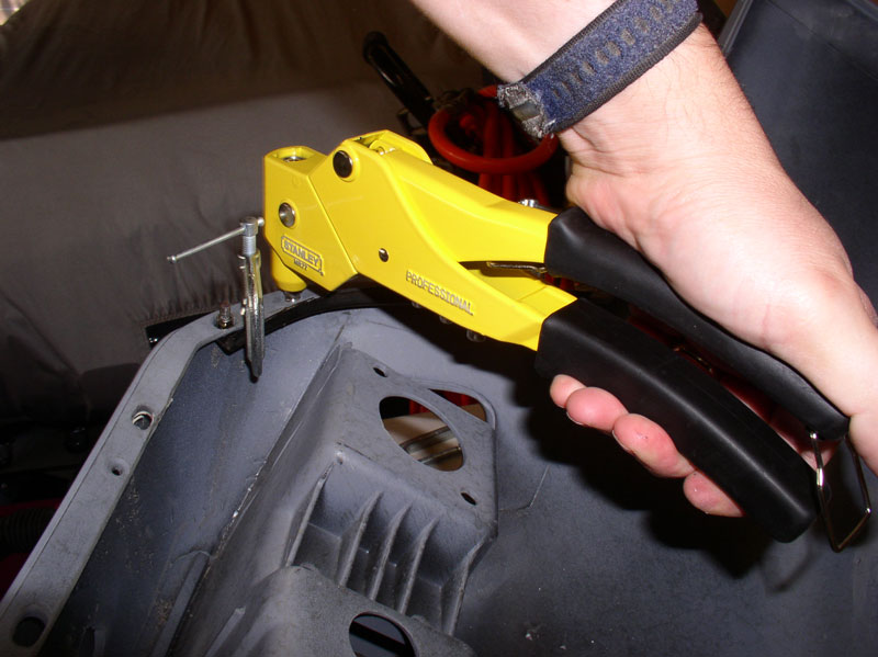
With the plate in position and rivets installed, compress and “pop” the rivets in place.
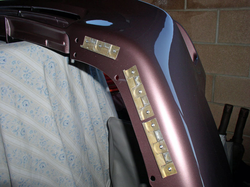
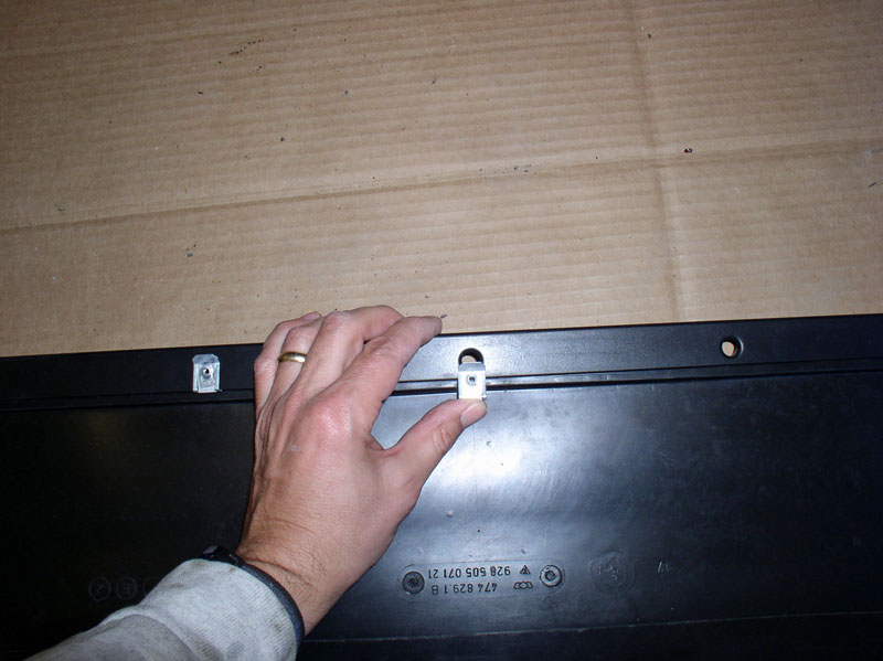
Position the top front reinforcement bar into place.
Rivet the reinforcement bar in place as shown.
At this point, I test fit the new bumper cover onto the fenders and secured it with the 8mm nuts. I then took the car to the local body and paint shop and they looked it over. We decided to smooth over one area on the bumper where a repair had been made to correct some damage that occurred during shipping. The body and paint shop then removed the bumper, did the color matching and I picked up the car a couple of hours later. About 3 days later, the bumper cover was ready to pick up from the shop – paint complete and ready to install. They recommended no wax or bra covers for 3-4 weeks.
I began the re-install by first installing the headlight squirters with gasket seals.
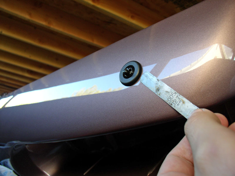
Install the gasket seal on the headlight squirter and position the headlight squirter on the bumper cover so the inlet end is horizontal and facing toward the center of the bumper cover as shown below. Install the plastic nut and hand tighten.
I then used a 24mm wrench to tighten down the headlight squirter but didn’t want to tighten it so much that it deformed the area around the squirter. I used a feeler gauge to make sure there were no significant gaps between the squirter and bumper cover.
I detached the hose assembly from the main supply line at the fender and connected the two ends to the head light squirters. I thought this was better as it would be easier to connect the main line at the splitter with one connection point rather than trying to connect both headlight squirters while installing the cover.
Next, I installed the spoiler clips to the underside of the bumper cover. The 1/8” (3mm) rivets in 1/8” length worked very well for this.
Position the support clip over the factory pre-drilled holes and install the rivets and “pop” them in place with the support clip oriented as shown below. The open edge of the support clip should be facing outward.
The support clips should look like the picture below when finished. Repeat for the other side.
I installed the signal light and fog light assemblies next and set the bumper cover on a table top with a box underneath the center grill as pictured below.
Continued....
If you go this route, you don’t need to fully install the cover. I just mounted the cover by attaching the sixteen 8mm studs/nuts that attach the cover to the bumper (8 on each side) and I installed the front reinforcement bar and adjusted the height of the cover. I did not install the rubber beading or the spoiler or wiring or anything else. That way, the paint shop could easily remove the cover by taking off the 8mm nuts and front reinforcement bar after making any adjustments that may be necessary. In addition, the shop needed to keep the car for a couple of hours to do the paint matching.
My next step was to re-install the studded back plates onto the bumper cover, I used 1/8” or 3mm diameter rivets in the 1/8” lengths as pictured below. These worked very well for all the mounting points except where there were reinforcement pads on the mounting holes. In these cases, I used longer rivets but still 3mm diameter.
First, I attached the side forward facing plates pictured below. I used small “C” clamps at first but found they were not really necessary.
With the plate in position and rivets installed, compress and “pop” the rivets in place.
Position the top front reinforcement bar into place.
Rivet the reinforcement bar in place as shown.
At this point, I test fit the new bumper cover onto the fenders and secured it with the 8mm nuts. I then took the car to the local body and paint shop and they looked it over. We decided to smooth over one area on the bumper where a repair had been made to correct some damage that occurred during shipping. The body and paint shop then removed the bumper, did the color matching and I picked up the car a couple of hours later. About 3 days later, the bumper cover was ready to pick up from the shop – paint complete and ready to install. They recommended no wax or bra covers for 3-4 weeks.
I began the re-install by first installing the headlight squirters with gasket seals.
Install the gasket seal on the headlight squirter and position the headlight squirter on the bumper cover so the inlet end is horizontal and facing toward the center of the bumper cover as shown below. Install the plastic nut and hand tighten.
I then used a 24mm wrench to tighten down the headlight squirter but didn’t want to tighten it so much that it deformed the area around the squirter. I used a feeler gauge to make sure there were no significant gaps between the squirter and bumper cover.
I detached the hose assembly from the main supply line at the fender and connected the two ends to the head light squirters. I thought this was better as it would be easier to connect the main line at the splitter with one connection point rather than trying to connect both headlight squirters while installing the cover.
Next, I installed the spoiler clips to the underside of the bumper cover. The 1/8” (3mm) rivets in 1/8” length worked very well for this.
Position the support clip over the factory pre-drilled holes and install the rivets and “pop” them in place with the support clip oriented as shown below. The open edge of the support clip should be facing outward.
The support clips should look like the picture below when finished. Repeat for the other side.
I installed the signal light and fog light assemblies next and set the bumper cover on a table top with a box underneath the center grill as pictured below.
Continued....
12-26-2010, 02:10 PM
#9
Rennlist Member
Thread Starter
Join Date: Sep 2007
Location: Ridgecrest, California
Posts: 1,363
Likes: 0
Received 143 Likes
on
28 Posts
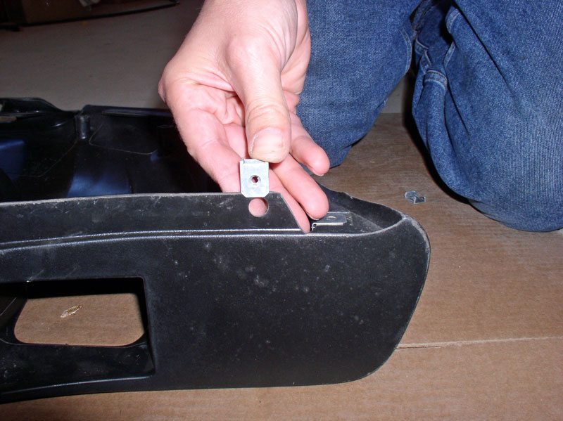
Install the fog light assembly cover support bracket first by orienting the end with the speed clips facing outward as pictured below.
Line up the holes in the bracket with the factory pre-drilled holes and rivet it in place.
The secured bracket should look like the pic below when done. Repeat for the other side.
Position the signal light in the bumper cover as shown below.
Position the fog light assembly in the bumper cover as well.
The washers used on the back of the signal light and fog lights have a raised lip on them. Install the washers with the lip facing the cover as shown below.
Install the side marker light harness clip on the bottom stud and install the two 8mm locknuts and tighten as shown below.
Install and tighten the three 8mm locknuts for the fog lamp as well. Two are next to the signal light….
…and one near the center of the bumper cover. Repeat for the other side.
On the front side, install the fog light mounting cover with two Phillips screws as shown. Repeat for the other side.
Install the center support bracket by attaching it to the bumper cover with Phillips screws. No need to tighten fully as you may need to adjust the support bracket when mated to the front of the car.
Prepare the underside of the fender by removing any remnants of the sealant between the fender and bumper cover. I used a gasket scraper to clean off the remains of the old sealant. I believe the sealant is used to help prevent excess water from collecting inside the bumper cover or perhaps to help keep the bumper cover from moving once installed.
I’ve had good luck with the 3M non-hardening Strip-Calk pictured below. I found this product at Car Quest.

Apply a small bead of the non-hardening sealant to the mating surface on the bumper cover. I applied about twice as much as needed in this picture below. You don’t want to apply too much as it will cause other issues with the bumper cover not fitting correctly. I placed the non-hardening sealant toward the inward facing edge of the bumper cover as shown below. Press the sealant out flat as possible. Repeat for the other side.
Position the bumper cover so that the mounting hardware is aligned on the cover and fenders. When you insert the fog light molding into the aluminum bumper, it should fit snuggly enough to hold the cover in place. I would recommend placing a piece of cardboard or blanket underneath the cover in case it is dropped during the install processe.
Continued....
Line up the holes in the bracket with the factory pre-drilled holes and rivet it in place.
The secured bracket should look like the pic below when done. Repeat for the other side.
Position the signal light in the bumper cover as shown below.
Position the fog light assembly in the bumper cover as well.
The washers used on the back of the signal light and fog lights have a raised lip on them. Install the washers with the lip facing the cover as shown below.
Install the side marker light harness clip on the bottom stud and install the two 8mm locknuts and tighten as shown below.
Install and tighten the three 8mm locknuts for the fog lamp as well. Two are next to the signal light….
…and one near the center of the bumper cover. Repeat for the other side.
On the front side, install the fog light mounting cover with two Phillips screws as shown. Repeat for the other side.
Install the center support bracket by attaching it to the bumper cover with Phillips screws. No need to tighten fully as you may need to adjust the support bracket when mated to the front of the car.
Prepare the underside of the fender by removing any remnants of the sealant between the fender and bumper cover. I used a gasket scraper to clean off the remains of the old sealant. I believe the sealant is used to help prevent excess water from collecting inside the bumper cover or perhaps to help keep the bumper cover from moving once installed.
I’ve had good luck with the 3M non-hardening Strip-Calk pictured below. I found this product at Car Quest.
Apply a small bead of the non-hardening sealant to the mating surface on the bumper cover. I applied about twice as much as needed in this picture below. You don’t want to apply too much as it will cause other issues with the bumper cover not fitting correctly. I placed the non-hardening sealant toward the inward facing edge of the bumper cover as shown below. Press the sealant out flat as possible. Repeat for the other side.
Position the bumper cover so that the mounting hardware is aligned on the cover and fenders. When you insert the fog light molding into the aluminum bumper, it should fit snuggly enough to hold the cover in place. I would recommend placing a piece of cardboard or blanket underneath the cover in case it is dropped during the install processe.
Continued....
12-26-2010, 02:19 PM
#10
Rennlist Member
Thread Starter
Join Date: Sep 2007
Location: Ridgecrest, California
Posts: 1,363
Likes: 0
Received 143 Likes
on
28 Posts
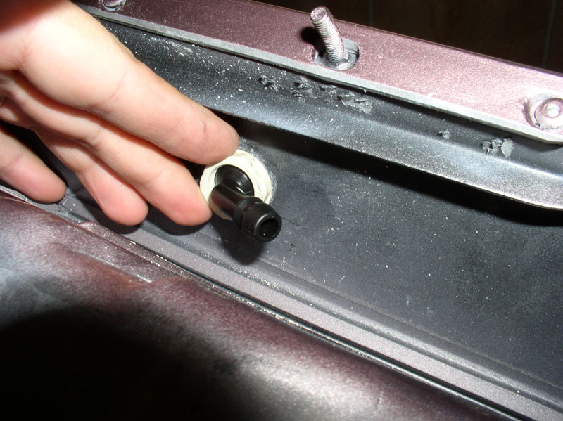
Connect the main head light squirter supply line to the splitter valve as shown.
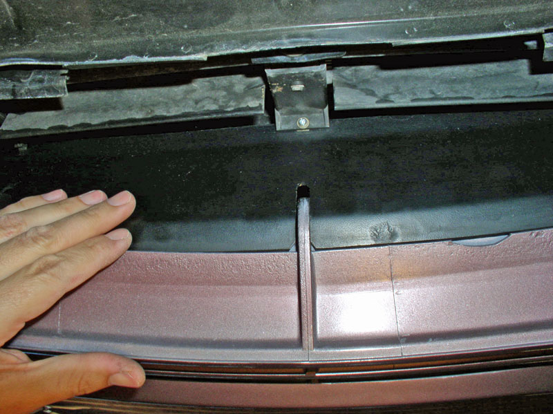
Align the slots in the air cowl with their respective tabs on the bumper cover as shown below.
The air cowl will fit into the slot formed on the bumper cover as indicated in the picture below. While you are maneuvering the bumper cover into place, ensure the cowl is aligning with this slot.
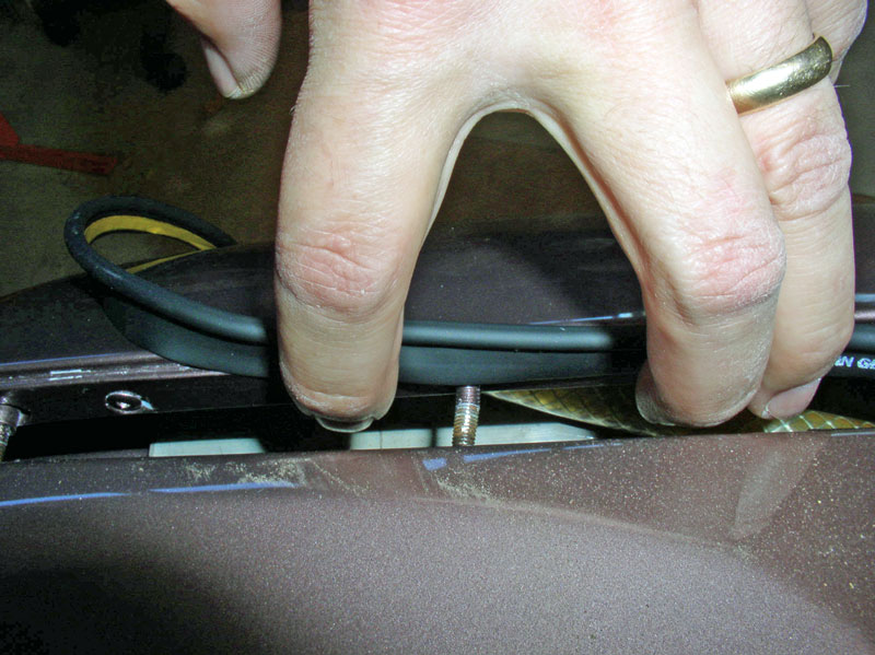
The tow hook receptacle located on the right (passenger side) will fit snuggly in the corner of the upper grill. As you are “pressing” the bumper cover into place, ensure it is not getting hung up on the tow hook receptacle.
On the backside of the bumper cover, ensure the signal and fog lamp wiring harnesses are positioned correctly. The fog lamp wiring harness is threaded through the aluminum bumper as shown below.
Continue pressing the bumper cover into position. Ensure the air cowl is aligned with the bumper cover tabs and slot as shown below.
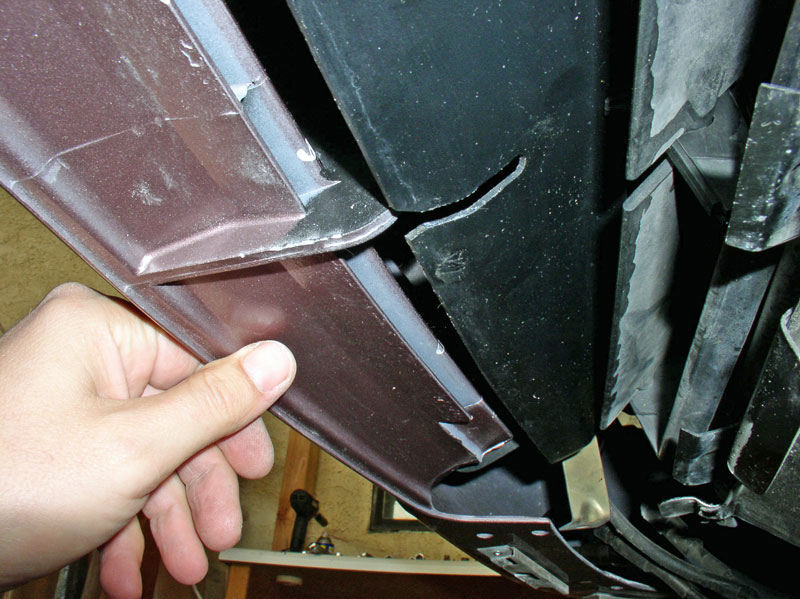
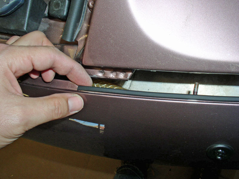
Press the bumper cover into place until there’s about an inch of distance to go before it’s fully seated as shown below. We will need a little maneuvering room to install the rubber fender beading.
You will notice the beading is pre-cut to length and has an adhesive strip. The bead will be installed with the adhesive strip attached to the bumper cover.
I found that the bumper cover mounting studs interfere with the beading adhesive strip and I decided to cut small notches in the beading adhesive strip to accommodate a consistent application of the beading.
First, I did a dry fit to confirm the beading was the correct length and see if any other “trimming” would be required. When beading is started at the proper location at the hood seam, there will be a small amount of “excess” beading at the end as shown below. You will not need to trim any of the beading.
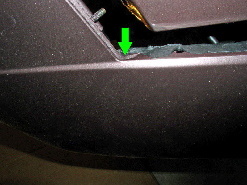
You will notice the bumper cover is designed with a small channel in the corner indicated by the green arrow below. This channel accommodates a small overlap of the beading.
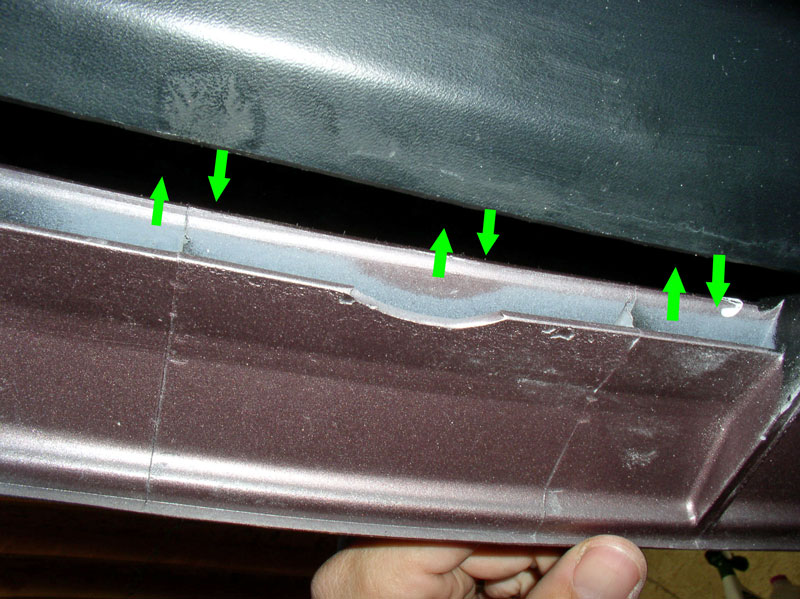
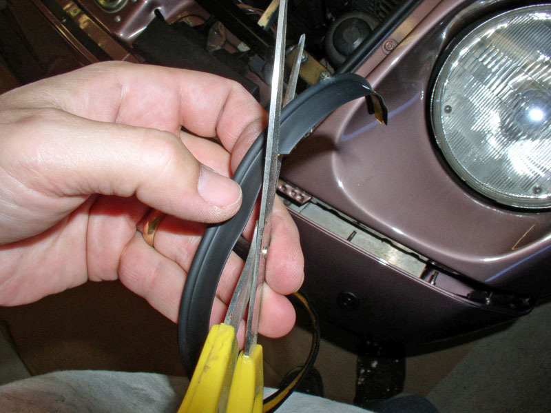
Holding the beading in place on the bumper cover, I marked the locations of each stud and cut a small “V” for each stud.
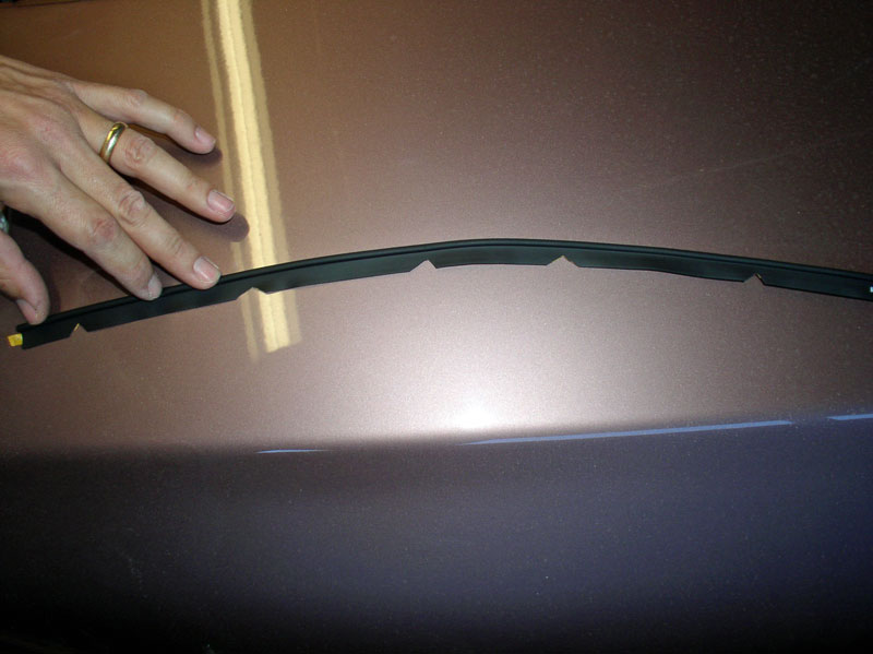
When finished, there should be 5 “V” notches cut and it should look something like the picture below.
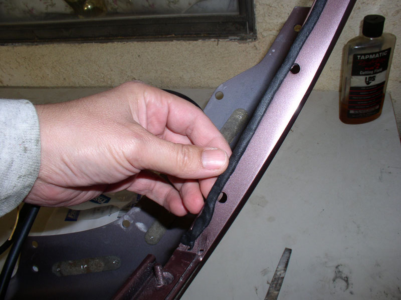
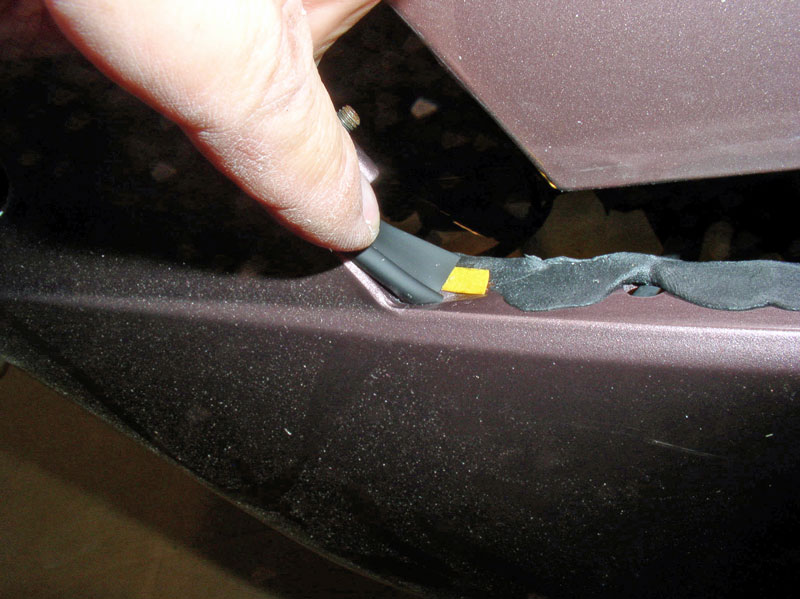
Peel the adhesive strip off the beading and position it into place on the bumper cover. The beading starts at the hood seam and is pressed in at the beginning of the hood “lip” on the bumper cover as depicted in the picture below. The height of the bead should be level with the surface edge of the bumper cover.
Confirm the height of the bead is level with the bumper cover and adjust if needed.
Continued....
Align the slots in the air cowl with their respective tabs on the bumper cover as shown below.
The air cowl will fit into the slot formed on the bumper cover as indicated in the picture below. While you are maneuvering the bumper cover into place, ensure the cowl is aligning with this slot.
The tow hook receptacle located on the right (passenger side) will fit snuggly in the corner of the upper grill. As you are “pressing” the bumper cover into place, ensure it is not getting hung up on the tow hook receptacle.
On the backside of the bumper cover, ensure the signal and fog lamp wiring harnesses are positioned correctly. The fog lamp wiring harness is threaded through the aluminum bumper as shown below.
Continue pressing the bumper cover into position. Ensure the air cowl is aligned with the bumper cover tabs and slot as shown below.
Press the bumper cover into place until there’s about an inch of distance to go before it’s fully seated as shown below. We will need a little maneuvering room to install the rubber fender beading.
You will notice the beading is pre-cut to length and has an adhesive strip. The bead will be installed with the adhesive strip attached to the bumper cover.
I found that the bumper cover mounting studs interfere with the beading adhesive strip and I decided to cut small notches in the beading adhesive strip to accommodate a consistent application of the beading.
First, I did a dry fit to confirm the beading was the correct length and see if any other “trimming” would be required. When beading is started at the proper location at the hood seam, there will be a small amount of “excess” beading at the end as shown below. You will not need to trim any of the beading.
You will notice the bumper cover is designed with a small channel in the corner indicated by the green arrow below. This channel accommodates a small overlap of the beading.
Holding the beading in place on the bumper cover, I marked the locations of each stud and cut a small “V” for each stud.
When finished, there should be 5 “V” notches cut and it should look something like the picture below.
Peel the adhesive strip off the beading and position it into place on the bumper cover. The beading starts at the hood seam and is pressed in at the beginning of the hood “lip” on the bumper cover as depicted in the picture below. The height of the bead should be level with the surface edge of the bumper cover.
Confirm the height of the bead is level with the bumper cover and adjust if needed.
Continued....
12-26-2010, 02:28 PM
#11
Rennlist Member
Thread Starter
Join Date: Sep 2007
Location: Ridgecrest, California
Posts: 1,363
Likes: 0
Received 143 Likes
on
28 Posts
Continue applying the beading around the curved corner of the bumper cover ensuring the height is level with the bumper cover. Repeat for the other side.
Press the bumper cover in the remaining distance and install the top support bracket shims (or washers) that were present before.
Begin tightening the five 8mm lock nuts from inside the wheel well as shown. I did not tighten fully as I needed to make adjustment later to ensure the cover was aligned with the height of the hood and fender before final tightening.
Install the lower support bracket.
Align the lower section of the bumper cover with the fender ensuring the alignment is consistent along the length of the lower half of the cover. I pressed the bumper cover in with one hand….
….while I installed and tightened the three 8mm locknuts on the inside as shown below.
Next, ensure the bumper cover height is aligned with the height of the hood and fender.
Looking down on the hood, fenders and bumper cover, ensure the gaps between the bumper cover and hood and fenders are consistent.
Ensure the beading is properly fitted into it’s channel as shown below. When all looks good, perform the final tightening on all the 8mm locknuts from inside the wheel wells for both sides of the bumper cover.
Install the side marker light wiring harness into its support clip as shown.
Reconnect the signal light and fog light wiring harnesses. They are keyed differently so it’s impossible to get them mixed up.
Install the signal and fog light harness connectors in their plastic clips as shown. Repeat for other side.
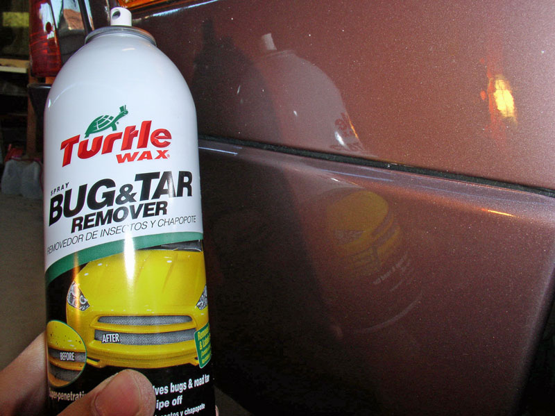
I found Turtle Wax Bug and Tar Remover to work very well at removing any excess non-hardening sealant from the fender-bumper cover seam.
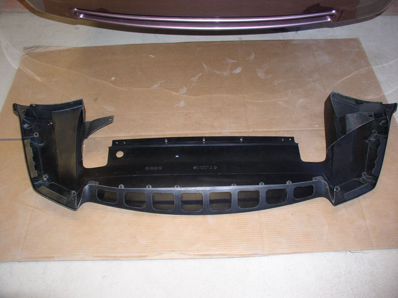
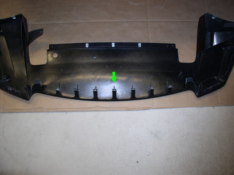
Next, I attached the spoiler to the bumper cover. The replacement spoiler I purchased was different than the original spoiler. The original part number of the ’87 spoiler was no longer available but the one pictured below for ’90 and later cars is still available. The main difference I noticed was the center leading edge has 8 cut outs in it with mounting tabs. The original was solid.
I also purchased a spoiler mounting kit because my original spoiler was missing some hardware and the remaining pieces were mismatched. Here’s a picture of the parts that come with the kit.
Continued....
Press the bumper cover in the remaining distance and install the top support bracket shims (or washers) that were present before.
Begin tightening the five 8mm lock nuts from inside the wheel well as shown. I did not tighten fully as I needed to make adjustment later to ensure the cover was aligned with the height of the hood and fender before final tightening.
Install the lower support bracket.
Align the lower section of the bumper cover with the fender ensuring the alignment is consistent along the length of the lower half of the cover. I pressed the bumper cover in with one hand….
….while I installed and tightened the three 8mm locknuts on the inside as shown below.
Next, ensure the bumper cover height is aligned with the height of the hood and fender.
Looking down on the hood, fenders and bumper cover, ensure the gaps between the bumper cover and hood and fenders are consistent.
Ensure the beading is properly fitted into it’s channel as shown below. When all looks good, perform the final tightening on all the 8mm locknuts from inside the wheel wells for both sides of the bumper cover.
Install the side marker light wiring harness into its support clip as shown.
Reconnect the signal light and fog light wiring harnesses. They are keyed differently so it’s impossible to get them mixed up.
Install the signal and fog light harness connectors in their plastic clips as shown. Repeat for other side.
I found Turtle Wax Bug and Tar Remover to work very well at removing any excess non-hardening sealant from the fender-bumper cover seam.
Next, I attached the spoiler to the bumper cover. The replacement spoiler I purchased was different than the original spoiler. The original part number of the ’87 spoiler was no longer available but the one pictured below for ’90 and later cars is still available. The main difference I noticed was the center leading edge has 8 cut outs in it with mounting tabs. The original was solid.
I also purchased a spoiler mounting kit because my original spoiler was missing some hardware and the remaining pieces were mismatched. Here’s a picture of the parts that come with the kit.
Continued....
12-26-2010, 02:44 PM
#12
Rennlist Member
Thread Starter
Join Date: Sep 2007
Location: Ridgecrest, California
Posts: 1,363
Likes: 0
Received 143 Likes
on
28 Posts
I installed the speed clips first. There are 3 on the trailing edge of the spoiler at the wheel well. One is on top, as picture below, and is used to mate the spoiler to the underside of the bumper cover..
The other 2 are on the upper edge where the splash shield mates with the spoiler.
Three speed clips are mounted to the rear center section of the spoiler for attaching the spoiler to the forward belly pan.
Install the 3 new spoiler/belly pan hangars as pictured below.
Install the 3 speed clips on the underside of the bumper cover as shown below.
Install a speed clip on the bumper cover support bracket as shown below.
Then swing the support bracket into place….
….so the speed clip is aligned with the factory pre-drilled hole in the bumper cover. At this point, I installed an 8mm screw at the location indicated by the green arrow below to secure the bracket to the bumper cover. I did this since the new spoiler did not have a pre-drilled hole for this mounting location like the spoiler for the ’87 did. If your spoiler has a pre-drilled hole, wait until the spoiler is mounted before installing this screw.
I performed a dry fit of the spoiler on the bumper cover and found that I could not get the spoiler to fit properly without the forward edge interfering with the air flaps. I surmised that the later style spoiler was designed for the later cars that did not have air flaps. After spending about an hour trying to make it work, I decided to simply cut the forward edge back so that the spoiler would fit without interfering with the air flaps. The picture below shows what the spoiler looks like after the trim.
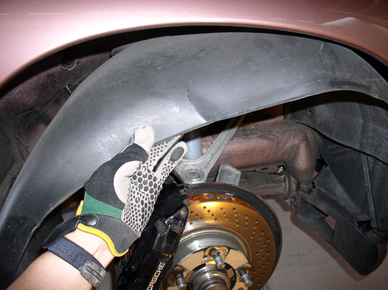
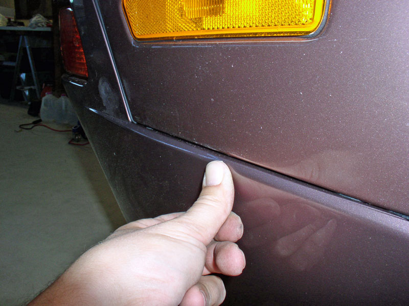
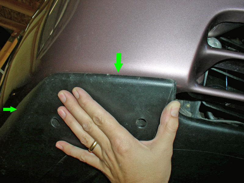
Position the spoiler underneath the bumper cover and slide it into the respective support clips. You will need to slide it backward and inward as indicated by the green arrows. Repeat for the other side. Then ensure the spoiler is properly centered on the front of the car. I did this by observing the location of the spoiler forward cutout (where my thumb is located in the picture below) with the location of the grill cut out on the bumper cover and ensured the distanced on both sides were consistent.
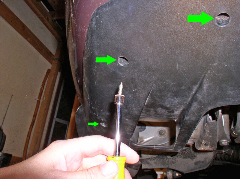
Once in position, I began installing the speed clip screws underneath the spoiler. There are three on each side that are installed in recessed holes as indicated by the arrows below.
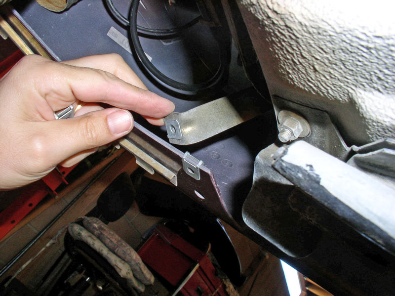
From inside the wheel well, attach the long support tab to the frame member with the 10mm bolt as shown below.
Install the 8mm speed clip screw at the trailing edge of the bumper cover as shown below. Repeat for the other side.
Position the 3 spoiler/belly pan support hangars between the metal bar and plastic spoiler as shown below.
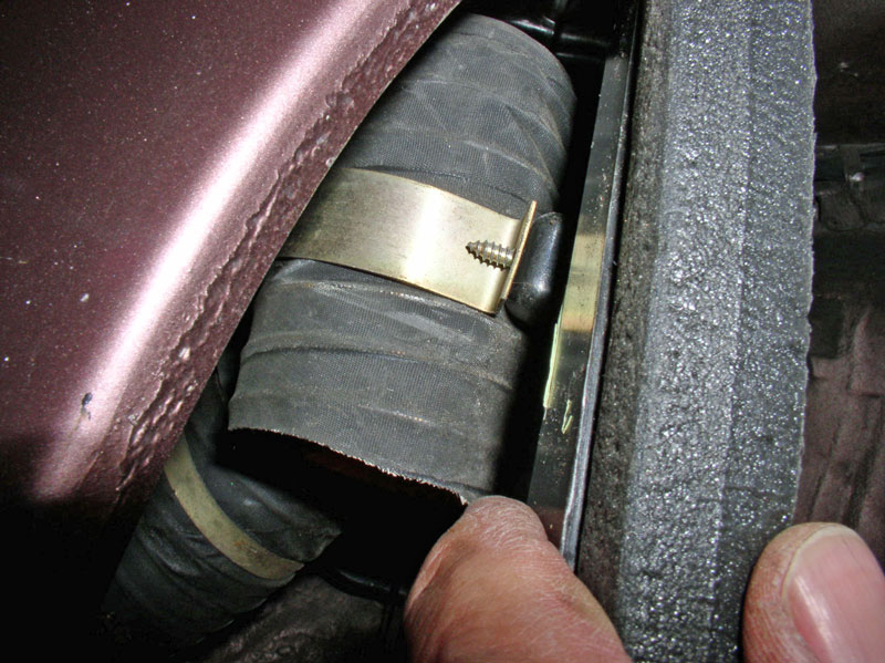
If you are replacing the splash shields or simply installing new foam sealant, now’s the time to install the foam sealant on the splash shields. On the left (driver’s side) wheel well, attach the alternator cooling hose to the back of the splash shield as shown. Also, re-attach the outside temperature sensor wiring harness to the zip tie on the back of the splash shield. If you are installing new splash shields, you will need to transfer the zip tie from the old splash shield to the new one (transfer, as well, the speed clips for the alternator cooling hose bracket and the speed clips for the wheel well liner).
Continued....
The other 2 are on the upper edge where the splash shield mates with the spoiler.
Three speed clips are mounted to the rear center section of the spoiler for attaching the spoiler to the forward belly pan.
Install the 3 new spoiler/belly pan hangars as pictured below.
Install the 3 speed clips on the underside of the bumper cover as shown below.
Install a speed clip on the bumper cover support bracket as shown below.
Then swing the support bracket into place….
….so the speed clip is aligned with the factory pre-drilled hole in the bumper cover. At this point, I installed an 8mm screw at the location indicated by the green arrow below to secure the bracket to the bumper cover. I did this since the new spoiler did not have a pre-drilled hole for this mounting location like the spoiler for the ’87 did. If your spoiler has a pre-drilled hole, wait until the spoiler is mounted before installing this screw.
I performed a dry fit of the spoiler on the bumper cover and found that I could not get the spoiler to fit properly without the forward edge interfering with the air flaps. I surmised that the later style spoiler was designed for the later cars that did not have air flaps. After spending about an hour trying to make it work, I decided to simply cut the forward edge back so that the spoiler would fit without interfering with the air flaps. The picture below shows what the spoiler looks like after the trim.
Position the spoiler underneath the bumper cover and slide it into the respective support clips. You will need to slide it backward and inward as indicated by the green arrows. Repeat for the other side. Then ensure the spoiler is properly centered on the front of the car. I did this by observing the location of the spoiler forward cutout (where my thumb is located in the picture below) with the location of the grill cut out on the bumper cover and ensured the distanced on both sides were consistent.
Once in position, I began installing the speed clip screws underneath the spoiler. There are three on each side that are installed in recessed holes as indicated by the arrows below.
From inside the wheel well, attach the long support tab to the frame member with the 10mm bolt as shown below.
Install the 8mm speed clip screw at the trailing edge of the bumper cover as shown below. Repeat for the other side.
Position the 3 spoiler/belly pan support hangars between the metal bar and plastic spoiler as shown below.
If you are replacing the splash shields or simply installing new foam sealant, now’s the time to install the foam sealant on the splash shields. On the left (driver’s side) wheel well, attach the alternator cooling hose to the back of the splash shield as shown. Also, re-attach the outside temperature sensor wiring harness to the zip tie on the back of the splash shield. If you are installing new splash shields, you will need to transfer the zip tie from the old splash shield to the new one (transfer, as well, the speed clips for the alternator cooling hose bracket and the speed clips for the wheel well liner).
Continued....
12-26-2010, 02:52 PM
#13
Rennlist Member
Thread Starter
Join Date: Sep 2007
Location: Ridgecrest, California
Posts: 1,363
Likes: 0
Received 143 Likes
on
28 Posts
Position the splash shield in place and secure with the 8mm screws. Repeat for the other side.
Position the wheel well liner in place lining up the mounting holes. Press the liner into position so the outer edge slips over the fender lip and locks into place.
Install the 10mm nut as shown.
Install the remaining 8mm screws that secure the liner to the car body.
Install the two 8mm screws that attach the liner to the forward splash shield. Repeat for the other side.
Re-install the front wheels, lower the car and torque down the wheel lug nuts to 95 ftlbs.
CONGRATULATIONS, you’re done!
As this was my first front bumper cover removal and install, I realize there are many ways to perform this work and I welcome feedback and comments on the procedure to improve the overall quality of this post. I'd like to thank Mark and Tom at 928 Int'l for the help in considering options for repairing/replacing the bumper cover and working with me to obtain a cover in great condition. THANKS, guys!
THANKS for reading!
12-26-2010, 03:10 PM
#14
Rennlist Member
Thread Starter
Join Date: Sep 2007
Location: Ridgecrest, California
Posts: 1,363
Likes: 0
Received 143 Likes
on
28 Posts
Let me be the first to welcome you back, with your amazing writeups! You along with they have been missed.
Although I have no immediate need for FBCRemoval, I find your threads interesting and entertianing, as I scratch my head in wonder - how do you keep your hands so clean?
Although I have no immediate need for FBCRemoval, I find your threads interesting and entertianing, as I scratch my head in wonder - how do you keep your hands so clean?

Seriously, I wear gloves occasionally and I do wash my hands at times when I'm taking pics.
Nice write-up! What type of rivets do you plan on installing? I have a small hand-rivet tool, but have never used it and I am wondering if it is suitable for such an application. Also can the threaded mounting studs that are fitted to the steel plates on the bumper cover be replaced? Several of mine are severely rusted/snapped off.
However, an inexpensive and easier alternative to replacing the studs may be to simply purchase a used replacement support bracket(s) from 928 Int'l now while they are having their year-end 1/2 off sale of used parts. It may be worth a call to see if they have any and what the sale price would be.
THANKS for the comment and questions!
THANKS for the comment, Sterling! I didn't realize I could cross-post to the DIY section - thought only moderators could do that but I'll look into it. THANKS!
