
HVAC COMPRESSOR RELAY REPAIR PROCEDURE w/PICS
 12-31-2010, 10:26 PM
#1
Rennlist Member
Thread Starter
Join Date: Sep 2007
Location: Ridgecrest, California
Posts: 1,363
Likes: 0
Received 143 Likes
on
28 Posts
HVAC COMPRESSOR RELAY REPLACEMENT PROCEDURE
This step-by-step pictorial guide details some A/C troubleshooting I followed to determine why the A/C compressor magnetic clutch was not engaging on my wife’s daily driver 928, Virginia (’87). It is not an exhaustive procedure for troubleshooting the problem but does contain some of the more obvious places to look for narrowing down the source of why the compressor may not be engaging.
This was the first time I have tried to troubleshoot and fix this type of problem so I did some research to see what others have tried. I found the WSM Ventilation, Heating, AC Wiring Diagram for the 1987 MY to be invaluable in addition to some posts on Rennlist. One write up in particular was extremely valuable in detailing how to address a failed A/C compressor relay located on the PC board inside the HVAC head unit. This write up was developed by Dr Bob on Rennlist and I found his write up on the Nichols site. Louis Ott’s addendum to the write up was also invaluable in that it identified an easy to obtain replacement relay. THANK YOU Dr Bob and Louis Ott and the Rennlist community!
WARNING: This is a Newbie-rated write up in that it provides a step-by-step pictorial guide to replacing the A/C compressor relay and contains approximately 85 pictures. I intended to provide this level of detail so other Newbies like me could try this repair on their own, if desired. This write up pertains to an ’87 MY 928. Other MY may have different or missing components depicted here.
PARTS-TOOLS-PREPARATION
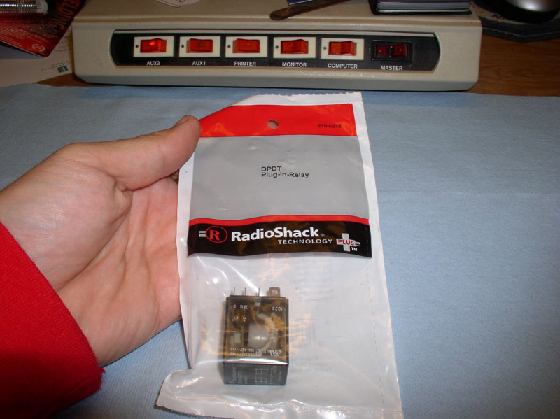
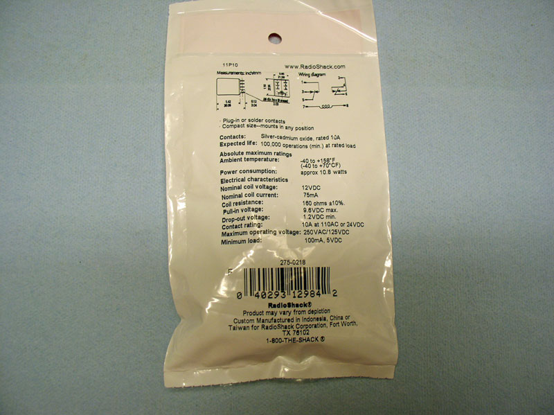
1) I purchased the Radio Shack Plug In Relay part number 275-0218 that was recommended by Louis Ott in response to Dr. Bob’s write up on the replacement procedure. Louis Ott’s recommended part number had a “C” following the Radio Shack part number but I could not find a relay with the “C”. A picture of the back of the relay package is included below for specification reference.
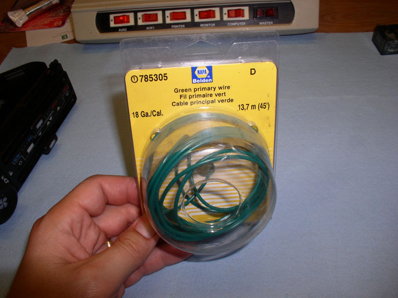
2. Approximately 3-4 feet of stranded 18 gauge wire
3. Approximately 3-4 inches of � inch heat shrink tubing.
4. Protected inline fuse and 3A fuse
TOOLS:
1. Multi-Meter (DC voltage and Ohms)
2. Soldering Iron, electrical solder, electrical soldering flux (I used a 15-watt soldering iron), a de-soldering vacuum (available at Radio Shack)
3. Heat Gun (or hair dryer)
PREPARATION:
Ensure the A/C system is fully charged with refrigerant before troubleshooting so you can eliminate the possibility of low refrigerant being the cause for the non-operational compressor.
I would also recommend studying the HVAC wiring diagram from the WSM and tracing the wiring and components that are needed to engage the compressor. I found this very educational.
Some background may be helpful on the symptoms I observed before diagnosing the problem. One day, while my wife was driving Virginia, she pressed the A/C button on the center console but no cold air came out. She promptly reported the problem to me, her favorite full-time 928 mechanic. I had replaced the compressor with a new rebuilt unit very recently and fully recharged the system so thought I must have done something wrong. I noticed the cooling fans engaging right on queue when the A/C button was pressed. This initially gave a Newb like me a false sense of security as I assumed the compressor was also engaging.
I thought, maybe I made a mistake on recharging the system so proceeded to recover the R-12 and recharge the system. Same thing – no cold air. I decided to look at the compressor while the A/C button was on and noticed the clutch was not engaged. It’s at times like these I stand and stare at the non-functioning component scratching my head and ask “Why aren’t you doing your job!”
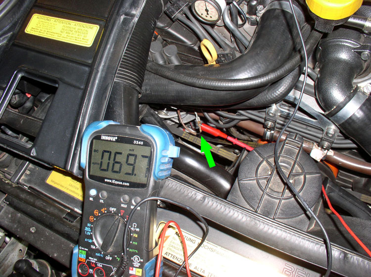
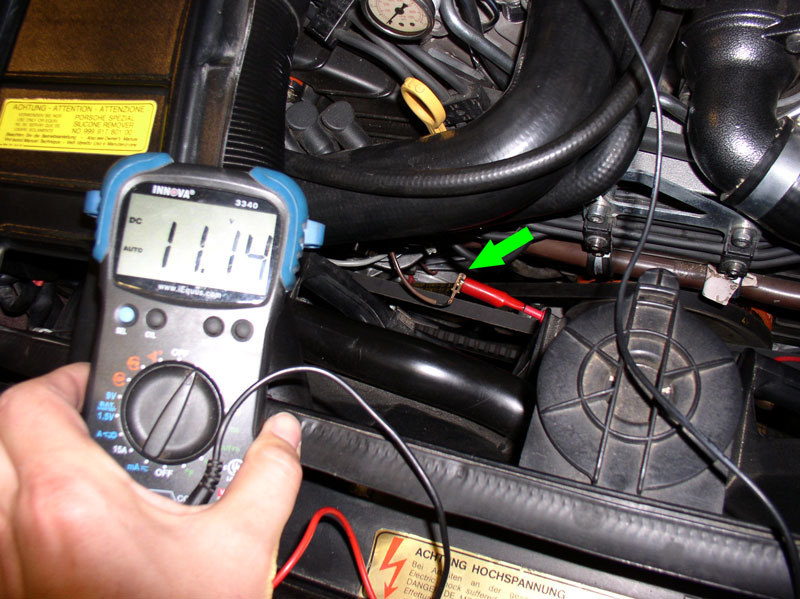
The first step in the troubleshooting was to determine if voltage was getting to the compressor. I removed the protective plastic casing where the compressor lead connected to the power lead so I could get good access to the leads for testing. When I depressed the A/C button on the center console, I only received 69.7 mVolts. This seemed strange but explained why the magnetic clutch was not engaging. I should be receiving battery voltage at this connection.
I decided to begin tracing backwards to see where the problem might be. I disconnected the power lead from the compressor lead and took a reading. This time I received battery voltage – 11.14 volts with the engine off but key on and A/C button depressed. This seemed really strange to me and I first thought something in the compressor itself may be defective. So to test that, I connected a test lead with alligator clip to the compressor lead and the other to the positive battery post in the engine bay. Presto! The magnetic clutch engages – no problem. So the compressor seemed to be working. But now I’m wondering why does battery voltage from the battery post work but battery voltage from the power lead doesn’t. It meant that SOMETHING between the power source into the HVAC head unit and the end of this power lead pictured below was not providing a true battery voltage supply with enough amps to drive the clutch.
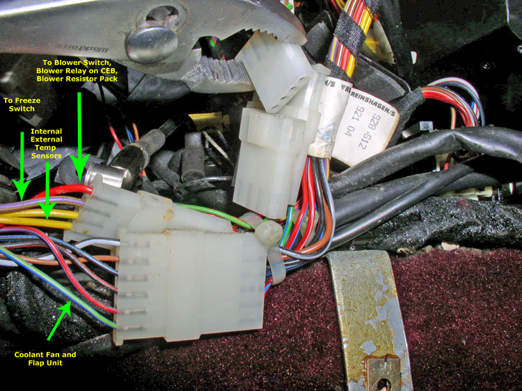
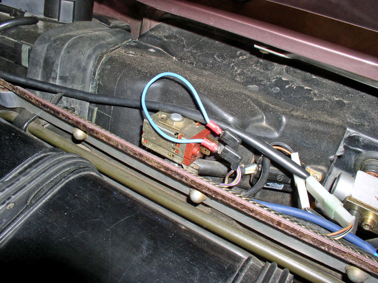
I found the WSM wiring diagram fascinating and traced the components that “touched” the power supply to the compressor. For those with inquiring minds, I’ve started at the HVAC head unit and briefly describe the wires and components involved. The picture below is inside the center console underneath the HVAC head unit on the right (passenger) side. I removed the console side cover and found a 4-pin and a 6-pin connector carrying HVAC related wiring. The 4-pin connector as the power lead wire that engages the compressor clutch. It’s the Violet wire next to the Red wire. The male side of the wire is coming from the HVAC head unit and is supposed to carry battery voltage when the A/C button is depressed and the lower slider control is not in the “off” position. The female side of the connector carries this voltage to the Freeze switch attached to the HVAC air box in the engine compartment. The Red wire supplies power to the Blower Switch, Blower relay on the CEB and to the Blower Resistor pack attached to the HVAC air box but does not affect compressor clutch operation. The yellow wires go to and from the external and internal temperature sensors but do not affect compressor clutch operation. On the 6-pin connector, the one wire of interest is the Blue/Green wire on the end. It supplies power to the cooling fans and flap unit. The male side of this wire is coming from the A/C button switch while the female side of the connector is sending voltage to the cooling fan and flap unit through the CEB.
When the A/C button is depressed, it sends power to two points of interest – one line directly to the coolant fan and flap unit without going through the HVAC Head Unit and one line goes back to the HVAC head unit and powers the relay that sends voltage to the compressor. Since the cooling fans would come on when the button was pressed, it indicated the A/C button itself was functioning properly. In other words, if voltage was getting to the cooling fans then I surmised voltage must also be getting to the HVAC head unit compressor relay.
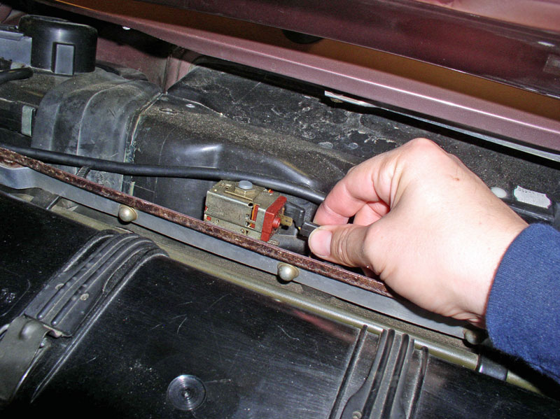
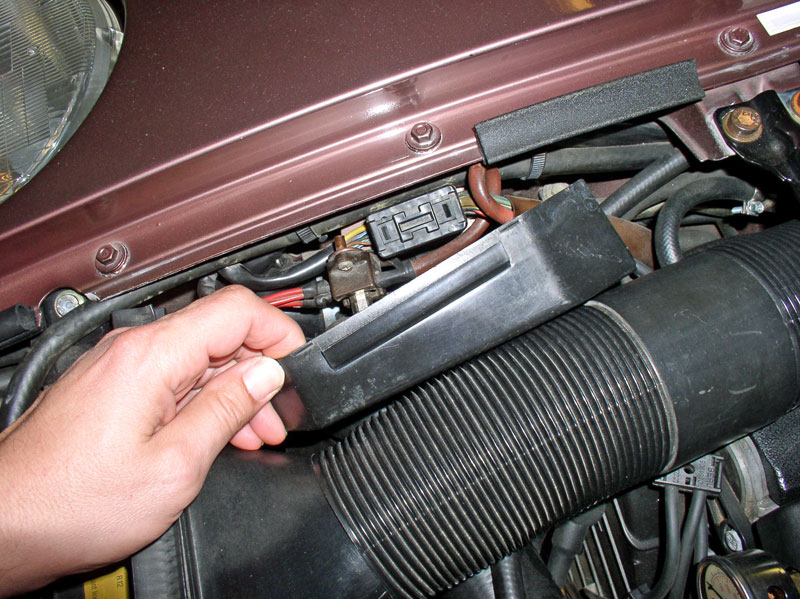
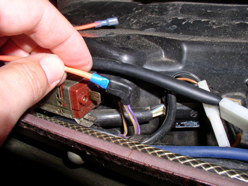
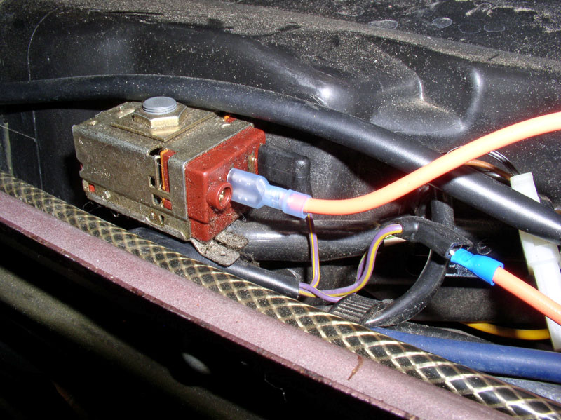
The first component in the line up to reach the compressor (after the HVAC head unit) is the freeze switch. Here’s a picture of the freeze switch. You will need to remove the plastic rain cover over the HVAC air box to get at it. The unit has incoming voltage supplied by the connector that has two (2) wires attached. The outgoing voltage is on the single wire connector. The single wire carrying outgoing voltage runs into the CEB and splits into two directions. One direction runs to the Suppressor Relay on the CEB (#XI for an ’87) and the other direction takes voltage out the CEB to the Refrigerant Low Pressure Switch. The freeze switch simply monitors the temperature of the evaporator core and opens the circuit if the temperature is at or below freezing. Opening the circuit cuts power to the compressor and prevents the evaporator from freezing up into a block of ice.
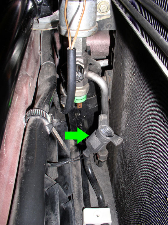
The next component down the voltage line to the compressor is the refrigerant Low Pressure Switch. It has one wire coming in and one wire going out. It simply monitors the pressure in the AC system and if the pressure is below the safe minimum, it opens the circuit which cuts power to the compressor. This preserves the compressor and helps prevent compressor damage from an inadequately charged system. The pressure switch is located underneath the high pressure port at the front of the condenser and is depicted by the upper green arrow below.
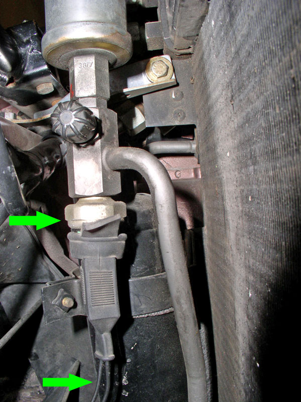
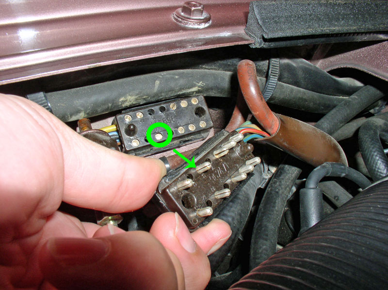
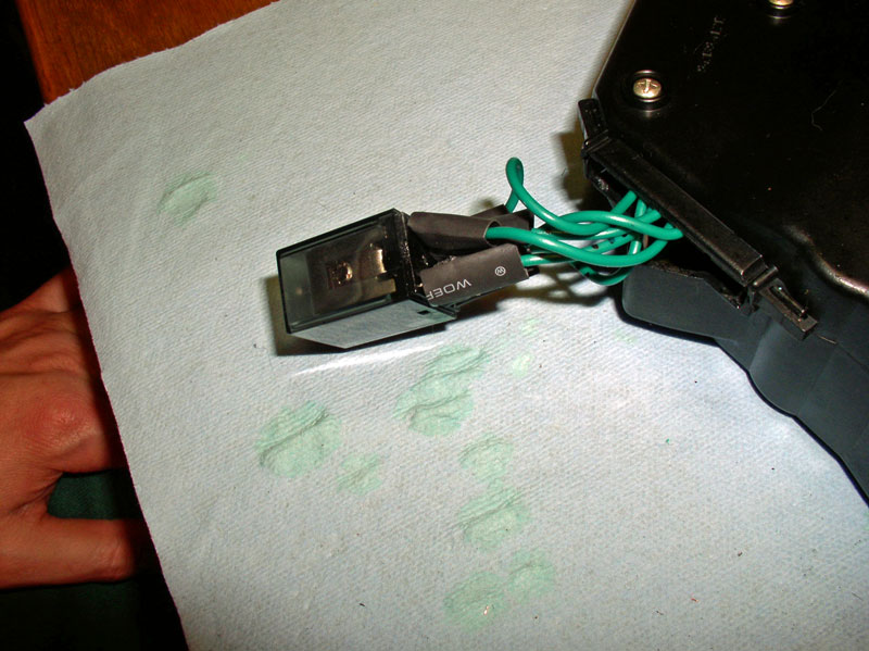
The final item worth checking in the line up to the compressor is the infamous 14-pin engine harness connector located at the battery post in the engine compartment. Remove the plastic cover and you’ll see the top of the black connector as seen below.
Power passes to the compressor through pin #9 in the connector. The female side is bringing voltage from the Low Pressure switch while the male side of the connector carries voltage directly to the compressor.

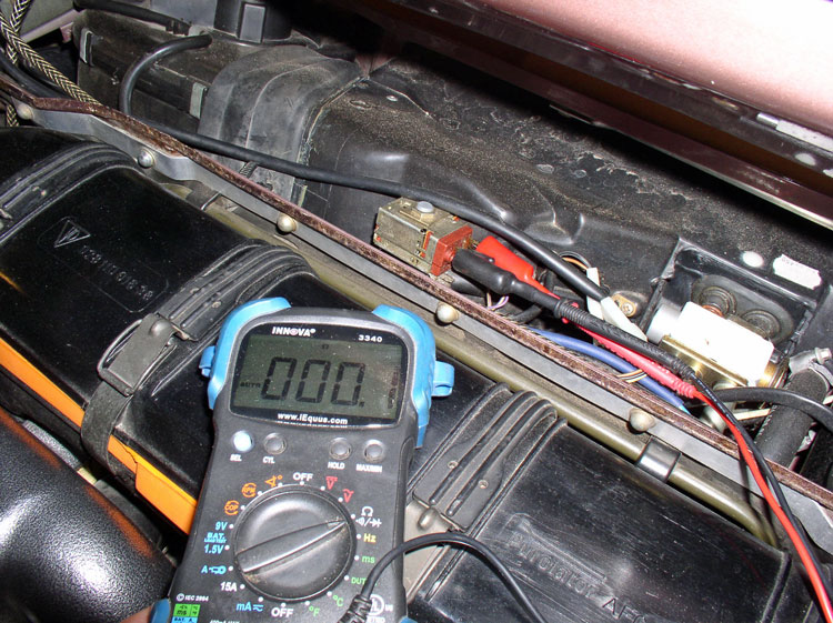
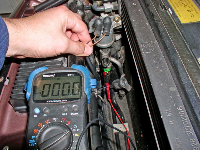
So I began testing each of these components to ensure none were contributing to the non-functioning compressor. I started with the Freeze Switch and performed a continuity test between the two connectors on the switch. Since temperature was well above freezing outside, the switch circuit should be closed and there should be continuity between the switch connectors. Connect up a multi-meter and check for resistance. My test below indicated 0.1 Ohms resistance indicating expected performance.
Next, I tested for incoming voltage to the switch. Incoming voltage should be present on the lead with two (2) wires attached. I fabricated a standard �” spade connector to both ends of some stranded 16 gauge wire….
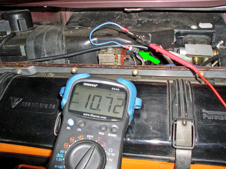
….and inserted the spade into the 2-wire connector and turned on the ignition but did not start the car and pressed the A/C button while the lower slider bar was not set to “off”. I received battery voltage. I ran the same test with the car running and received 13.5 volts. So I concluded power was getting to the freeze switch but I could not determine if it had sufficient amperage to drive the magnetic clutch.
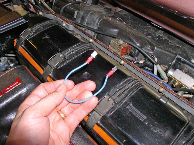
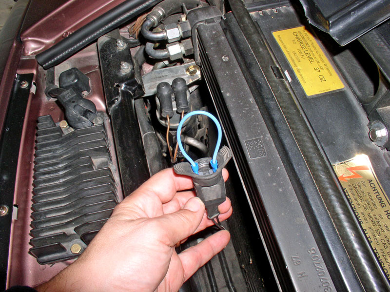
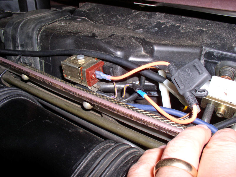
To completely eliminate the possibility of interference of the Freeze Switch with the compressor voltage, I jumpered the switch with the jumper wire as shown below and left it in place for the next test. Since the output wire from the Freeze Switch goes to the CEB next and splits in two, I decided to test the CEB next. One of the paths taken by the Freeze Switch wire coming into the CEB goes to the Suppressor Relay (#XI). I decided to replace the XI relay with a known working A/C unit in Oregon (also an '87 MY). After swapping the XI relays, the compressor problem persisted on Virginia. I concluded the Suppressor Relay was either performing as expected or it had no impact on the power supplied to the compressor. I swapped back the XI relays and continued my tests with the Low Press Switch next.
At the Low Pressure Switch, disconnect the harness lead by pulling downward on the rubber connector cover.
Continued....
This step-by-step pictorial guide details some A/C troubleshooting I followed to determine why the A/C compressor magnetic clutch was not engaging on my wife’s daily driver 928, Virginia (’87). It is not an exhaustive procedure for troubleshooting the problem but does contain some of the more obvious places to look for narrowing down the source of why the compressor may not be engaging.
This was the first time I have tried to troubleshoot and fix this type of problem so I did some research to see what others have tried. I found the WSM Ventilation, Heating, AC Wiring Diagram for the 1987 MY to be invaluable in addition to some posts on Rennlist. One write up in particular was extremely valuable in detailing how to address a failed A/C compressor relay located on the PC board inside the HVAC head unit. This write up was developed by Dr Bob on Rennlist and I found his write up on the Nichols site. Louis Ott’s addendum to the write up was also invaluable in that it identified an easy to obtain replacement relay. THANK YOU Dr Bob and Louis Ott and the Rennlist community!
WARNING: This is a Newbie-rated write up in that it provides a step-by-step pictorial guide to replacing the A/C compressor relay and contains approximately 85 pictures. I intended to provide this level of detail so other Newbies like me could try this repair on their own, if desired. This write up pertains to an ’87 MY 928. Other MY may have different or missing components depicted here.
PARTS-TOOLS-PREPARATION
1) I purchased the Radio Shack Plug In Relay part number 275-0218 that was recommended by Louis Ott in response to Dr. Bob’s write up on the replacement procedure. Louis Ott’s recommended part number had a “C” following the Radio Shack part number but I could not find a relay with the “C”. A picture of the back of the relay package is included below for specification reference.
2. Approximately 3-4 feet of stranded 18 gauge wire
3. Approximately 3-4 inches of � inch heat shrink tubing.
4. Protected inline fuse and 3A fuse
TOOLS:
1. Multi-Meter (DC voltage and Ohms)
2. Soldering Iron, electrical solder, electrical soldering flux (I used a 15-watt soldering iron), a de-soldering vacuum (available at Radio Shack)
3. Heat Gun (or hair dryer)
PREPARATION:
Ensure the A/C system is fully charged with refrigerant before troubleshooting so you can eliminate the possibility of low refrigerant being the cause for the non-operational compressor.
I would also recommend studying the HVAC wiring diagram from the WSM and tracing the wiring and components that are needed to engage the compressor. I found this very educational.
Some background may be helpful on the symptoms I observed before diagnosing the problem. One day, while my wife was driving Virginia, she pressed the A/C button on the center console but no cold air came out. She promptly reported the problem to me, her favorite full-time 928 mechanic. I had replaced the compressor with a new rebuilt unit very recently and fully recharged the system so thought I must have done something wrong. I noticed the cooling fans engaging right on queue when the A/C button was pressed. This initially gave a Newb like me a false sense of security as I assumed the compressor was also engaging.
I thought, maybe I made a mistake on recharging the system so proceeded to recover the R-12 and recharge the system. Same thing – no cold air. I decided to look at the compressor while the A/C button was on and noticed the clutch was not engaged. It’s at times like these I stand and stare at the non-functioning component scratching my head and ask “Why aren’t you doing your job!”
The first step in the troubleshooting was to determine if voltage was getting to the compressor. I removed the protective plastic casing where the compressor lead connected to the power lead so I could get good access to the leads for testing. When I depressed the A/C button on the center console, I only received 69.7 mVolts. This seemed strange but explained why the magnetic clutch was not engaging. I should be receiving battery voltage at this connection.
I decided to begin tracing backwards to see where the problem might be. I disconnected the power lead from the compressor lead and took a reading. This time I received battery voltage – 11.14 volts with the engine off but key on and A/C button depressed. This seemed really strange to me and I first thought something in the compressor itself may be defective. So to test that, I connected a test lead with alligator clip to the compressor lead and the other to the positive battery post in the engine bay. Presto! The magnetic clutch engages – no problem. So the compressor seemed to be working. But now I’m wondering why does battery voltage from the battery post work but battery voltage from the power lead doesn’t. It meant that SOMETHING between the power source into the HVAC head unit and the end of this power lead pictured below was not providing a true battery voltage supply with enough amps to drive the clutch.
I found the WSM wiring diagram fascinating and traced the components that “touched” the power supply to the compressor. For those with inquiring minds, I’ve started at the HVAC head unit and briefly describe the wires and components involved. The picture below is inside the center console underneath the HVAC head unit on the right (passenger) side. I removed the console side cover and found a 4-pin and a 6-pin connector carrying HVAC related wiring. The 4-pin connector as the power lead wire that engages the compressor clutch. It’s the Violet wire next to the Red wire. The male side of the wire is coming from the HVAC head unit and is supposed to carry battery voltage when the A/C button is depressed and the lower slider control is not in the “off” position. The female side of the connector carries this voltage to the Freeze switch attached to the HVAC air box in the engine compartment. The Red wire supplies power to the Blower Switch, Blower relay on the CEB and to the Blower Resistor pack attached to the HVAC air box but does not affect compressor clutch operation. The yellow wires go to and from the external and internal temperature sensors but do not affect compressor clutch operation. On the 6-pin connector, the one wire of interest is the Blue/Green wire on the end. It supplies power to the cooling fans and flap unit. The male side of this wire is coming from the A/C button switch while the female side of the connector is sending voltage to the cooling fan and flap unit through the CEB.
When the A/C button is depressed, it sends power to two points of interest – one line directly to the coolant fan and flap unit without going through the HVAC Head Unit and one line goes back to the HVAC head unit and powers the relay that sends voltage to the compressor. Since the cooling fans would come on when the button was pressed, it indicated the A/C button itself was functioning properly. In other words, if voltage was getting to the cooling fans then I surmised voltage must also be getting to the HVAC head unit compressor relay.
The first component in the line up to reach the compressor (after the HVAC head unit) is the freeze switch. Here’s a picture of the freeze switch. You will need to remove the plastic rain cover over the HVAC air box to get at it. The unit has incoming voltage supplied by the connector that has two (2) wires attached. The outgoing voltage is on the single wire connector. The single wire carrying outgoing voltage runs into the CEB and splits into two directions. One direction runs to the Suppressor Relay on the CEB (#XI for an ’87) and the other direction takes voltage out the CEB to the Refrigerant Low Pressure Switch. The freeze switch simply monitors the temperature of the evaporator core and opens the circuit if the temperature is at or below freezing. Opening the circuit cuts power to the compressor and prevents the evaporator from freezing up into a block of ice.
The next component down the voltage line to the compressor is the refrigerant Low Pressure Switch. It has one wire coming in and one wire going out. It simply monitors the pressure in the AC system and if the pressure is below the safe minimum, it opens the circuit which cuts power to the compressor. This preserves the compressor and helps prevent compressor damage from an inadequately charged system. The pressure switch is located underneath the high pressure port at the front of the condenser and is depicted by the upper green arrow below.
The final item worth checking in the line up to the compressor is the infamous 14-pin engine harness connector located at the battery post in the engine compartment. Remove the plastic cover and you’ll see the top of the black connector as seen below.
Power passes to the compressor through pin #9 in the connector. The female side is bringing voltage from the Low Pressure switch while the male side of the connector carries voltage directly to the compressor.
So I began testing each of these components to ensure none were contributing to the non-functioning compressor. I started with the Freeze Switch and performed a continuity test between the two connectors on the switch. Since temperature was well above freezing outside, the switch circuit should be closed and there should be continuity between the switch connectors. Connect up a multi-meter and check for resistance. My test below indicated 0.1 Ohms resistance indicating expected performance.
Next, I tested for incoming voltage to the switch. Incoming voltage should be present on the lead with two (2) wires attached. I fabricated a standard �” spade connector to both ends of some stranded 16 gauge wire….
….and inserted the spade into the 2-wire connector and turned on the ignition but did not start the car and pressed the A/C button while the lower slider bar was not set to “off”. I received battery voltage. I ran the same test with the car running and received 13.5 volts. So I concluded power was getting to the freeze switch but I could not determine if it had sufficient amperage to drive the magnetic clutch.
To completely eliminate the possibility of interference of the Freeze Switch with the compressor voltage, I jumpered the switch with the jumper wire as shown below and left it in place for the next test. Since the output wire from the Freeze Switch goes to the CEB next and splits in two, I decided to test the CEB next. One of the paths taken by the Freeze Switch wire coming into the CEB goes to the Suppressor Relay (#XI). I decided to replace the XI relay with a known working A/C unit in Oregon (also an '87 MY). After swapping the XI relays, the compressor problem persisted on Virginia. I concluded the Suppressor Relay was either performing as expected or it had no impact on the power supplied to the compressor. I swapped back the XI relays and continued my tests with the Low Press Switch next.
At the Low Pressure Switch, disconnect the harness lead by pulling downward on the rubber connector cover.
Continued....
Last edited by Dwayne; 01-03-2011 at 10:14 PM.
 12-31-2010, 10:52 PM
#2
Nordschleife Master
If your PCB has the yellow original relay, there's also an alternative relay that's a direct replacement on the PCB and is rated high enough to actually take the current draw.
See this thread for info and pics:
https://rennlist.com/forums/928-foru...tch-relay.html
Apparently however, if your PCB has the blue relay, then Dwayne's replacement is the way to go as there is no drop-in replacement.
Thanks Dwayne - the troubleshooting info is invaluable!
See this thread for info and pics:
https://rennlist.com/forums/928-foru...tch-relay.html
Apparently however, if your PCB has the blue relay, then Dwayne's replacement is the way to go as there is no drop-in replacement.
Thanks Dwayne - the troubleshooting info is invaluable!
12-31-2010, 10:54 PM
#3
Rennlist Member
Thread Starter
Join Date: Sep 2007
Location: Ridgecrest, California
Posts: 1,363
Likes: 0
Received 143 Likes
on
28 Posts
Knowing the system was fully charged, I tested the Low Pressure Switch for continuity. When the system has greater than the minimum pressure in it, the circuit in the switch should be closed and voltage should pass through. With the multi-meter, I took a reading on the two switch connectors as indicated below and received 0.0 Ohms reading indicating expected performance from the Low Pressure Switch.
I fabricated a second jumper wire with male spade connectors and jumpered the switch connector to eliminate any possibility of interference from the Low Pressure Switch on the compressor voltage. Still, the compressor magnetic clutch would not engage.
Lastly, I tested the 14-pin wiring harness for expected voltage. With the A/C switch depressed and the lower slider **** not in the �off� position, I received battery voltage at the female side of pin #9 as expected. I inspected both male and female connectors and they were clean. I applied battery voltage from the battery post to the male pin #9 and the compressor clutch engaged. I surmised that the 14-pin connector was not contributing to the compressor voltage problem.
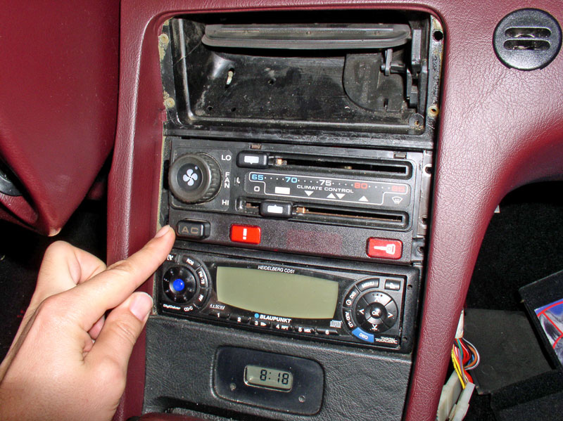
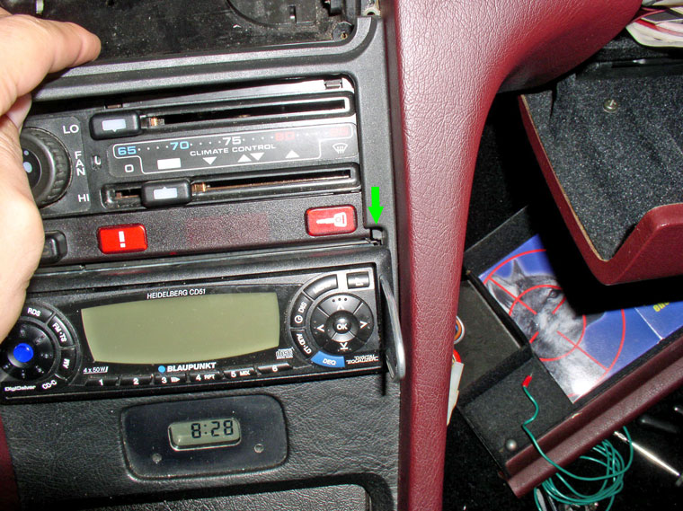
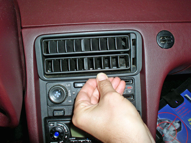
At this point, I concluded that NONE of the wiring or components tested were contributing to the �funky� voltage problem to the compressor. I had eliminated all possible sources except one � the HVAC Head Unit. Before I started this procedure and testing, I didn�t know a compressor power relay even existed within the HVAC Head Unit. I learned that from reading some posts on Rennlist which pointed me to Dr Bob�s write up. With the testing completed so far, this relay HAD to be the culprit. I began removing the head unit from the center console. I used an angled pick tool to carefully pry console trim away.
The first piece to remove is the center vent. I place the flap lever at mid-position and use the hooked tool to reach in behind the vent and carefully pull out. I pull out each side a little at a time so as not to break off the locating tabs on the back side.
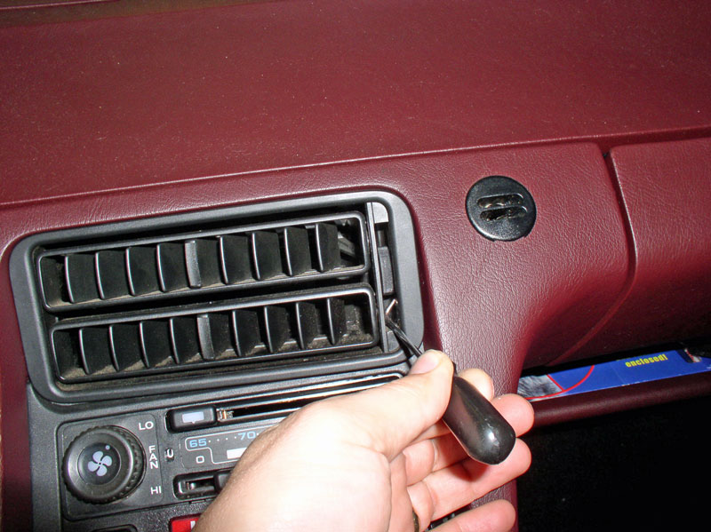
Remove the vent cover.
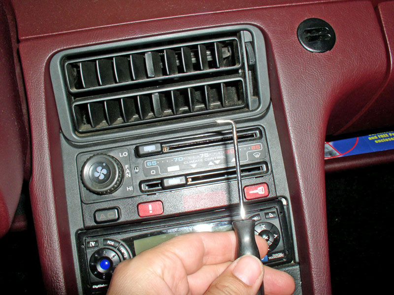
Gently pry up the trim piece pictured below with a small screwdriver being careful not to gouge the center console.
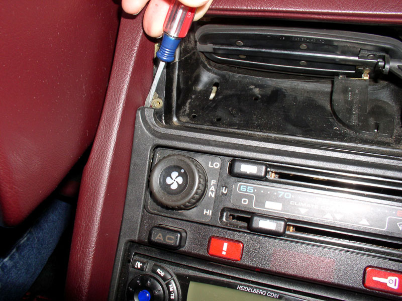
Once the trim is removed from its groove at the top on one side, pull that side forward toward the vent slightly so the locking tab indicated by the green arrow below clears the radio face plate. Then lift that side up and out. You can repeat for the other side of the trim being careful not to break the small tab.
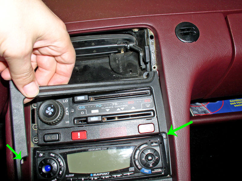
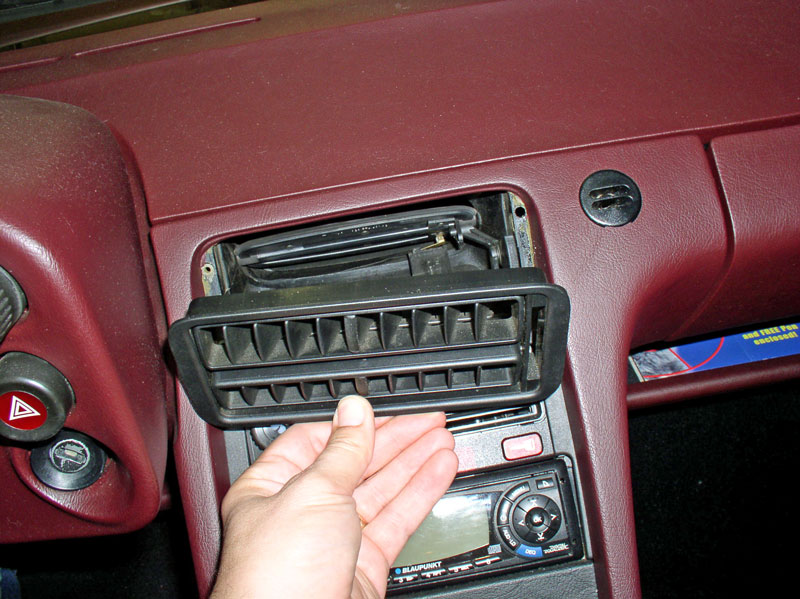
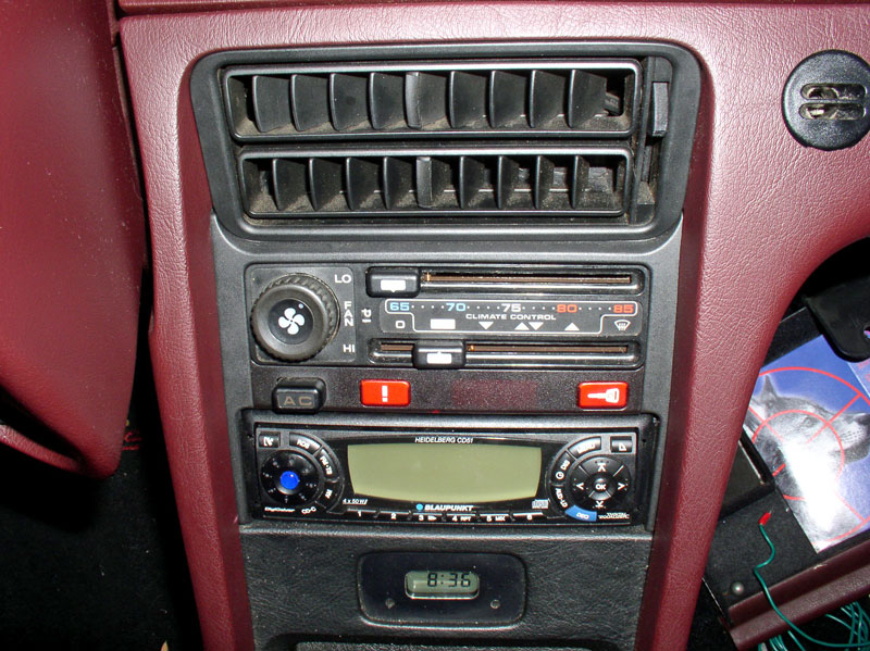
Next, remove the 4 Phillips head screws (2 each side) that secure the head unit to the center console. Also remove the 2 Phillips head screws (one each side) that secure the A/C Button, door lock and warning indicator button bar to the console.
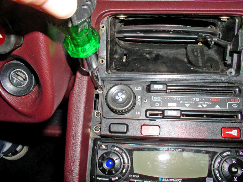
When removing the small screws and washers, consider using a magnetic pick-up tool to extract the screws so they don�t fall into an abyss and get lost.
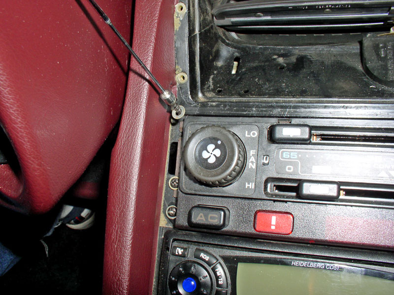
Gently pull the head unit out of the console.
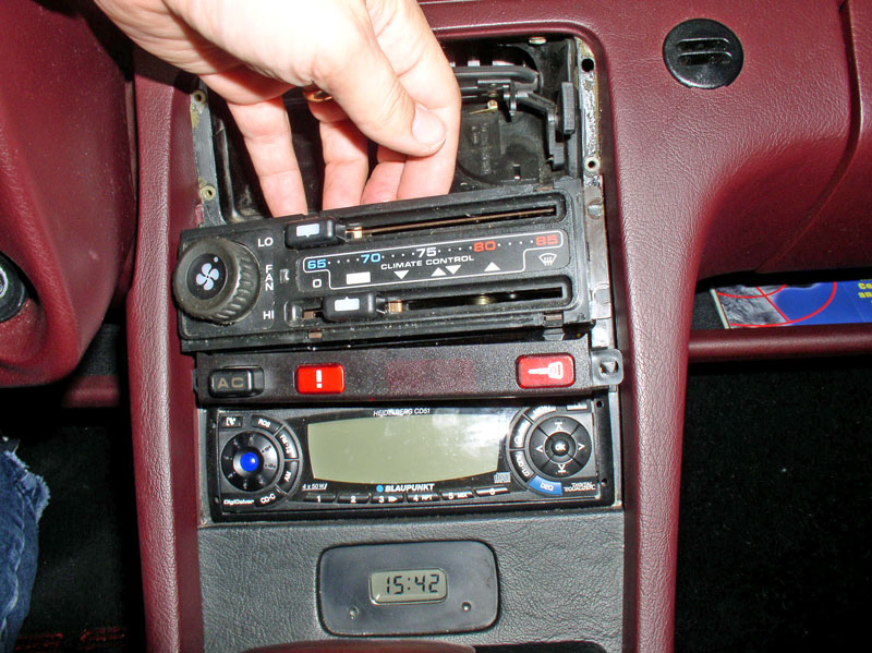
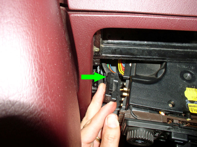
As you are pulling the head unit out, remove the forward harness connector as shown below. You may need to use a flat blade screwdriver to pry the connector loose at first.
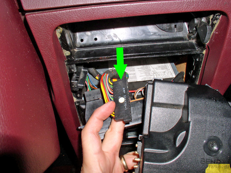
Disconnect the rearward wiring harness as well. At this point, the head unit should be free of the center console.
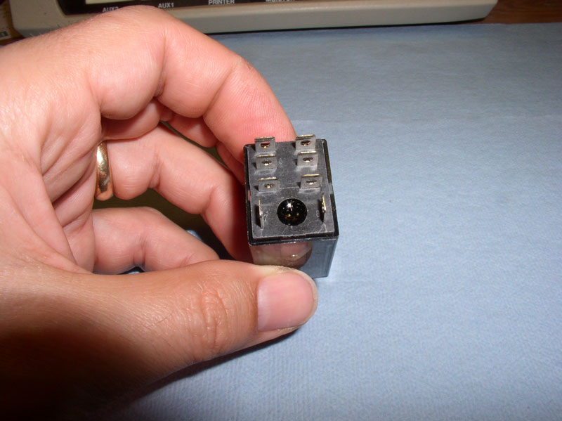
Next, prepare a clean work surface to disassemble the head unit and perform the repairs. Here�s a picture of the new replacement relay I purchased from Radio Shack. This relay costs about $8.00.
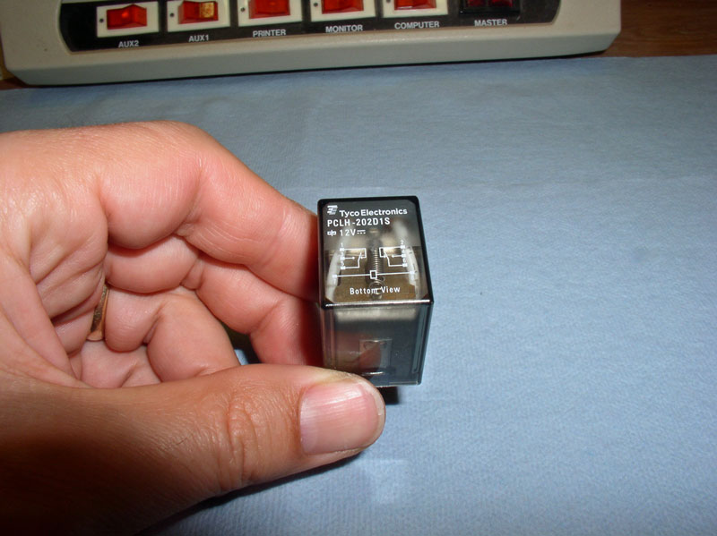
The backside shown here has 8 pins. We�ll only be using 6 of these pins. They are numbered 1-8 and correspond to the numbers printed on the top of the relay schematic.
Continued....
I fabricated a second jumper wire with male spade connectors and jumpered the switch connector to eliminate any possibility of interference from the Low Pressure Switch on the compressor voltage. Still, the compressor magnetic clutch would not engage.
Lastly, I tested the 14-pin wiring harness for expected voltage. With the A/C switch depressed and the lower slider **** not in the �off� position, I received battery voltage at the female side of pin #9 as expected. I inspected both male and female connectors and they were clean. I applied battery voltage from the battery post to the male pin #9 and the compressor clutch engaged. I surmised that the 14-pin connector was not contributing to the compressor voltage problem.
At this point, I concluded that NONE of the wiring or components tested were contributing to the �funky� voltage problem to the compressor. I had eliminated all possible sources except one � the HVAC Head Unit. Before I started this procedure and testing, I didn�t know a compressor power relay even existed within the HVAC Head Unit. I learned that from reading some posts on Rennlist which pointed me to Dr Bob�s write up. With the testing completed so far, this relay HAD to be the culprit. I began removing the head unit from the center console. I used an angled pick tool to carefully pry console trim away.
The first piece to remove is the center vent. I place the flap lever at mid-position and use the hooked tool to reach in behind the vent and carefully pull out. I pull out each side a little at a time so as not to break off the locating tabs on the back side.
Remove the vent cover.
Gently pry up the trim piece pictured below with a small screwdriver being careful not to gouge the center console.
Once the trim is removed from its groove at the top on one side, pull that side forward toward the vent slightly so the locking tab indicated by the green arrow below clears the radio face plate. Then lift that side up and out. You can repeat for the other side of the trim being careful not to break the small tab.
Next, remove the 4 Phillips head screws (2 each side) that secure the head unit to the center console. Also remove the 2 Phillips head screws (one each side) that secure the A/C Button, door lock and warning indicator button bar to the console.
When removing the small screws and washers, consider using a magnetic pick-up tool to extract the screws so they don�t fall into an abyss and get lost.
Gently pull the head unit out of the console.
As you are pulling the head unit out, remove the forward harness connector as shown below. You may need to use a flat blade screwdriver to pry the connector loose at first.
Disconnect the rearward wiring harness as well. At this point, the head unit should be free of the center console.
Next, prepare a clean work surface to disassemble the head unit and perform the repairs. Here�s a picture of the new replacement relay I purchased from Radio Shack. This relay costs about $8.00.
The backside shown here has 8 pins. We�ll only be using 6 of these pins. They are numbered 1-8 and correspond to the numbers printed on the top of the relay schematic.
Continued....
12-31-2010, 11:11 PM
#4
Rennlist Member
Thread Starter
Join Date: Sep 2007
Location: Ridgecrest, California
Posts: 1,363
Likes: 0
Received 143 Likes
on
28 Posts
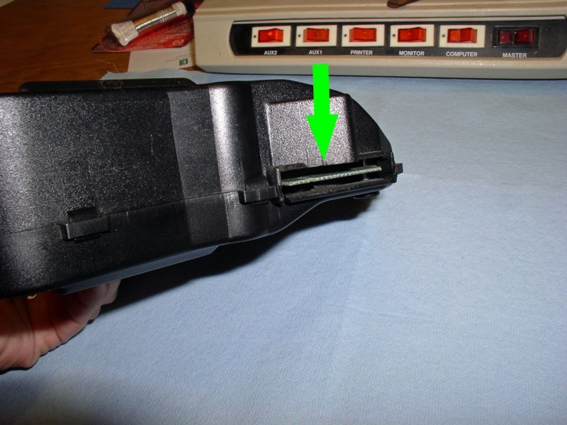
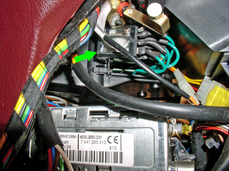
I followed Dr Bob�s recommended location for externally mounting the new relay as well as the area for the wire leads to emerge from the inside of the head unit. This area is at the unused port at the back of the unit depicted by the green arrow below.
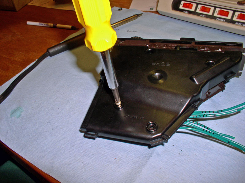
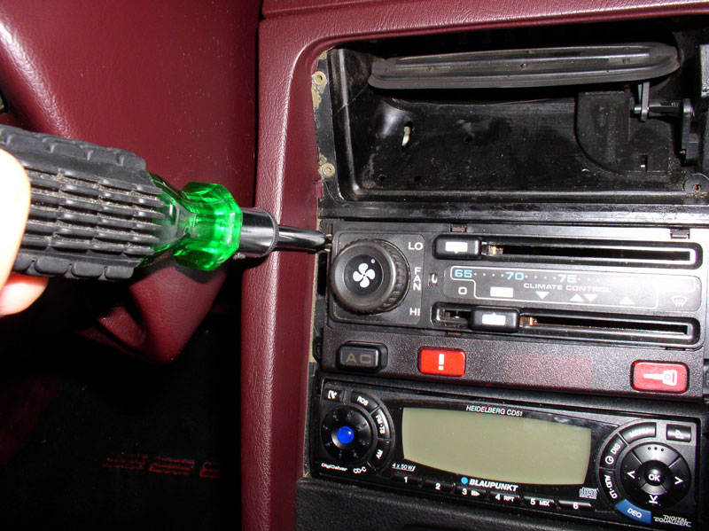
Begin by removing the 2 Phillips Head screws on the top of the unit.
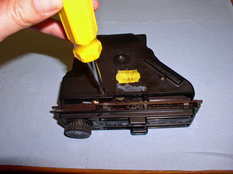
Turn the unit over and remove the 4 Phillips Head screws there.
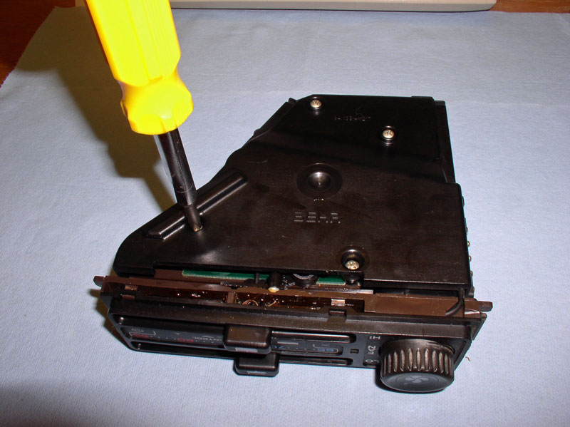
I noticed that 2 screws found on top were shorter than the 4 screws found on the bottom.
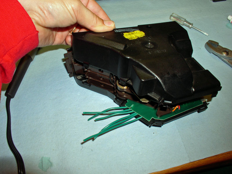
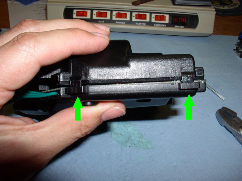
Begin prying the two halves of the head unit covers apart. I stared with the side with the used electric ports. It has just one small locking tab that easily separates with the use of a small flat blade screwdriver.
Next, I used the small screwdriver to carefully pry the opposite side of the covers apart. There are two locking tabs on this side as seen in the picture below.
The two rear tabs would not separate so easily, I discovered. Therefore, I had to find a really small screwdriver and I pushed it directly up into the locking tab then levered the screwdriver upward to disengage the lock tab.
With all lock tabs disengaged, remove the upper cover.
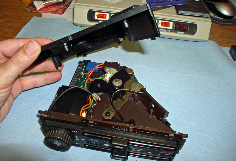
Remove the lower cover.
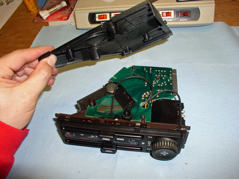
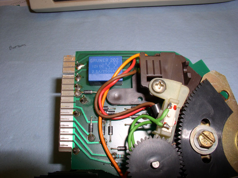
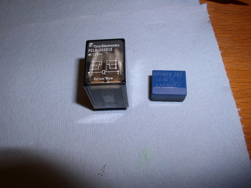
On the top side of the unit, I found the faulty relay. It was colored blue for my unit. The top of the relay has the schematic and spec ratings. It�s a 12 volt relay rated for 2.5 amps. I understand from Louis Ott�s addition to Dr Bob�s write up that the compressor is expected to draw about 3.5 amps at 13.5 volts so it should not be a surprise for these relays to fail.
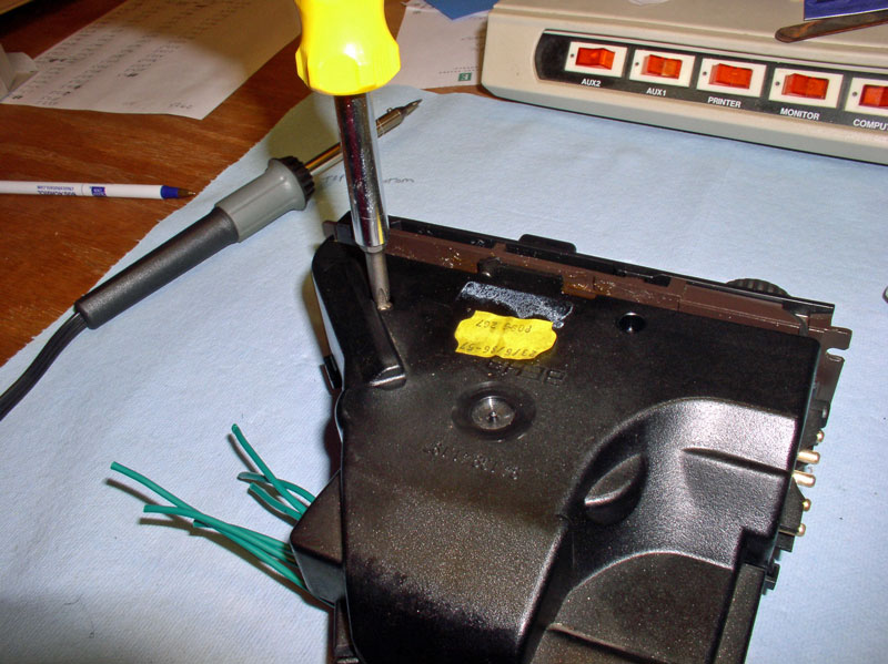
I turned the unit over exposing the soldered relay pins. They are marked with the RED dots in the picture below. I carefully heated the solder of one of the pins to the point of melting then used the vacuum method of sucking up the melted solder. I then moved to the next pin until all 8 were desoldered. I looked for a solder wick or desoldering vacuum tool locally but could not find one. I improvised by purchasing a 1 � � adapter for a vacuum cleaner attachment hose and used that instead. Later on when I was out of town, I stopped by a Radio Shack and purchased a desoldering vacuum tool. Dr Bob cautions against overheating the PC board so I didn�t linger on any of the soldering points.
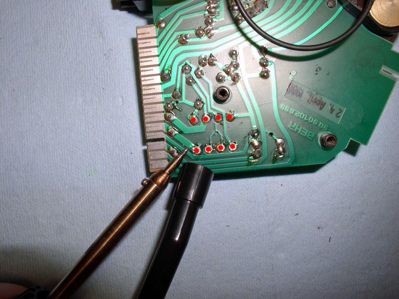
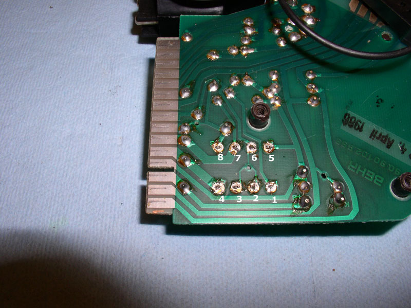
When all the joints have been desoldered, it should look something like the picture below. My eyesight isn�t what it used to be (getting older is a bummer!) so I used a magnifying glass to closely inspect each pin to make sure the pins were free of remaining solder. Once the solder is removed, you may notice the pins are numbered (pins 1, 4, 5, and 8 on the PC board). The pin numbers are annotated in the pic below for clarity.
From the top side, you should be able to remove the relay. I used a pair of pliers in order to get a better grip.
Here is a comparison of the two relays. You can see the new relay is substantially beefier than the original relay.
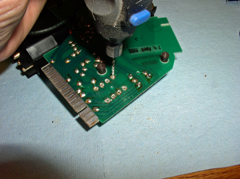
The PC board pin holes will need to be enlarged slightly to accommodate the 18 gauge wire with solder. I used a 1/16� drill bit with my variable speed dremel set to the lowest speed. Dr Bob�s write up recommends using a small pin vice to drill the holes out by hand but I did not have such a device handy so I improvised and used the smallest drilling device I had and it worked out well.
Continued....
Begin by removing the 2 Phillips Head screws on the top of the unit.
Turn the unit over and remove the 4 Phillips Head screws there.
I noticed that 2 screws found on top were shorter than the 4 screws found on the bottom.
Begin prying the two halves of the head unit covers apart. I stared with the side with the used electric ports. It has just one small locking tab that easily separates with the use of a small flat blade screwdriver.
Next, I used the small screwdriver to carefully pry the opposite side of the covers apart. There are two locking tabs on this side as seen in the picture below.
The two rear tabs would not separate so easily, I discovered. Therefore, I had to find a really small screwdriver and I pushed it directly up into the locking tab then levered the screwdriver upward to disengage the lock tab.
With all lock tabs disengaged, remove the upper cover.
Remove the lower cover.
On the top side of the unit, I found the faulty relay. It was colored blue for my unit. The top of the relay has the schematic and spec ratings. It�s a 12 volt relay rated for 2.5 amps. I understand from Louis Ott�s addition to Dr Bob�s write up that the compressor is expected to draw about 3.5 amps at 13.5 volts so it should not be a surprise for these relays to fail.
I turned the unit over exposing the soldered relay pins. They are marked with the RED dots in the picture below. I carefully heated the solder of one of the pins to the point of melting then used the vacuum method of sucking up the melted solder. I then moved to the next pin until all 8 were desoldered. I looked for a solder wick or desoldering vacuum tool locally but could not find one. I improvised by purchasing a 1 � � adapter for a vacuum cleaner attachment hose and used that instead. Later on when I was out of town, I stopped by a Radio Shack and purchased a desoldering vacuum tool. Dr Bob cautions against overheating the PC board so I didn�t linger on any of the soldering points.
When all the joints have been desoldered, it should look something like the picture below. My eyesight isn�t what it used to be (getting older is a bummer!) so I used a magnifying glass to closely inspect each pin to make sure the pins were free of remaining solder. Once the solder is removed, you may notice the pins are numbered (pins 1, 4, 5, and 8 on the PC board). The pin numbers are annotated in the pic below for clarity.
From the top side, you should be able to remove the relay. I used a pair of pliers in order to get a better grip.
Here is a comparison of the two relays. You can see the new relay is substantially beefier than the original relay.
The PC board pin holes will need to be enlarged slightly to accommodate the 18 gauge wire with solder. I used a 1/16� drill bit with my variable speed dremel set to the lowest speed. Dr Bob�s write up recommends using a small pin vice to drill the holes out by hand but I did not have such a device handy so I improvised and used the smallest drilling device I had and it worked out well.
Continued....
12-31-2010, 11:26 PM
#5
Rennlist Member
Thread Starter
Join Date: Sep 2007
Location: Ridgecrest, California
Posts: 1,363
Likes: 0
Received 143 Likes
on
28 Posts
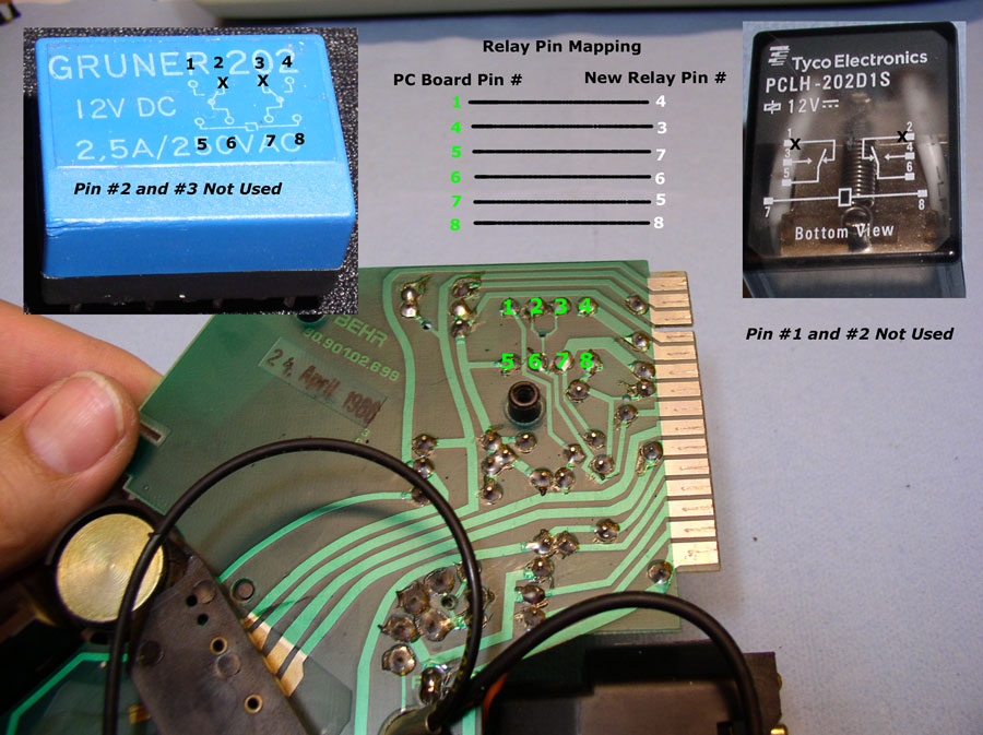
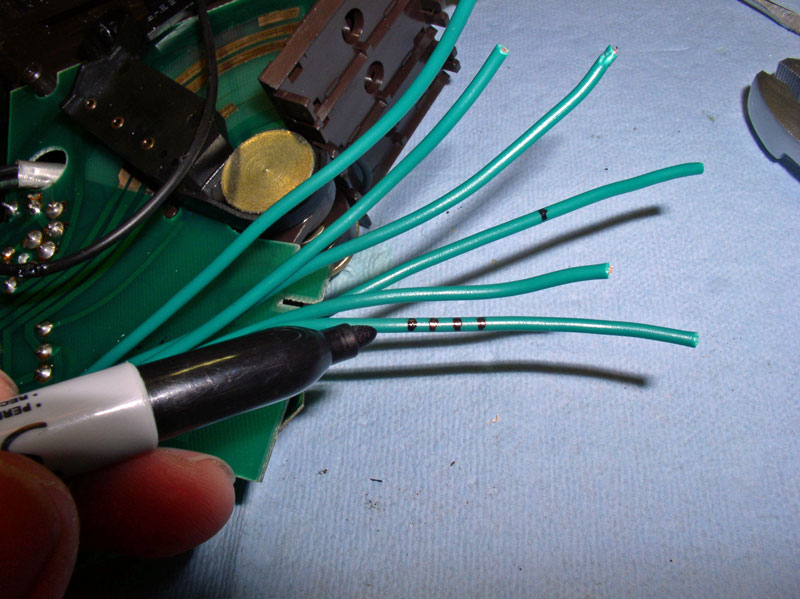
Now I was ready to solder the new wires in but first some thought needs to be given to the relay pin mapping. The pin mapping may vary for your application if you are using a different replacement relay but the following logic would still apply. I have noted the pin numbering on the PC board in the picture below and they correspond to the pin numbering on the original relay schematic inset in the upper left of the pic below. Notice pins #2 and #3 are not used. The replacement relay pin schematic is also inset below in the upper right of the pic below. Notice pins #1 and #2 are not used. In the upper center of the pic below, I have listed the pin mapping I used. The key here is to keep the power switching pin assignments preserved in the mapping. For example, on the original schematic (upper left inset), pin #6 power is switched to pin #1. It�s a coincidence that pin #6 on the new relay is also supplied power so I mapped pin number #6 on the original relay to pin #6 on the new relay. That requires that pin #1 on the original relay MUST be mapped to pin #4 on the new relay since #4 is the switched power for pin #6 on the new relay (see below). Following this logic, I wrote down the pin assignments from original relay to new relay. Since the pin assignments on the original relay match the pin holes on the PC board, I now have mapping assignments of the wires (that will be installed next) to the new relay. Each wire will be marked as to what PC board pin hole it is soldered to. Then it�s simply a matter of soldering each wire to the new relay tabs using the mapping below.
First, I prepared the strips of 18 gauge stranded wire. I cut these to lengths of 6-7� and tinned the ends with solder. I have little to no experience with soldering but found the job is a lot easier when electrical solder flux is used. I left the opposite end unprepared since this was my first repair of this type, I thought I might need to trim the wires down further after installed. As it turns out, I did not have to trim any of the wires down so you could go ahead and strip the opposite ends of the wires and tin them as well.
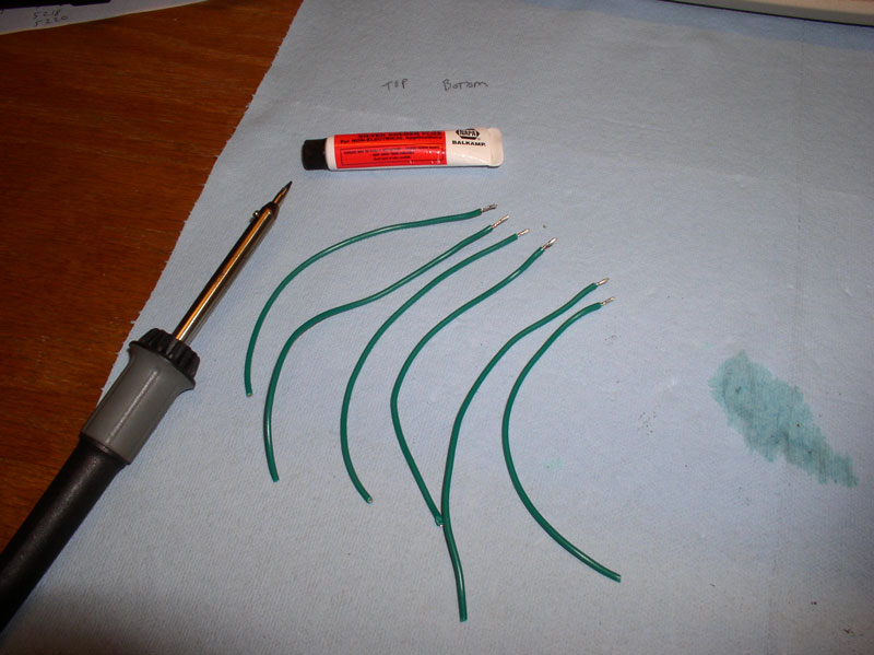
I then bent each wire end that was to be soldered to the PC board at a 90 degree angle as shown.
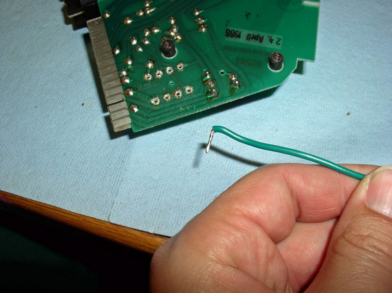
Place the wire in the hole to be soldered as shown below. Since I�m right-handed, I found it easier to begin soldering with pin #1 as seen below then solder pin #4 next.
I bent the wire upward as shown below so that it would stay in position while I soldered it in place.
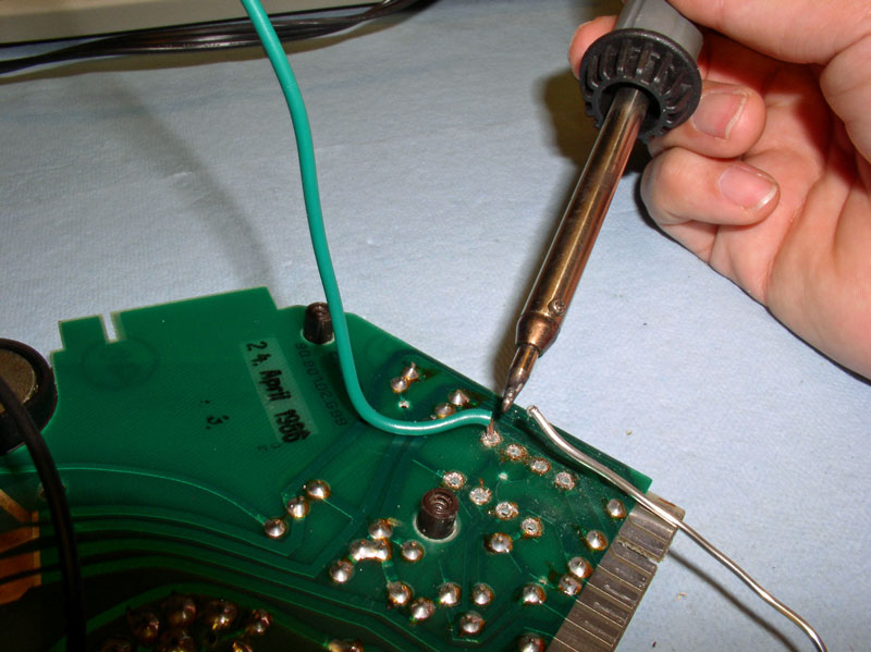
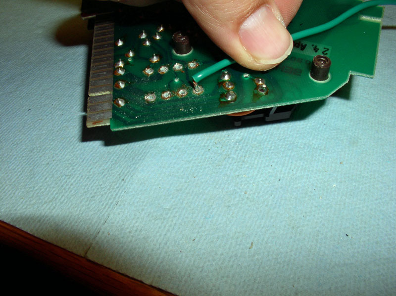
Again, be careful not to overhead the PC board when soldering. I found the soldering flux to be a big help in improving solder flow. When the soldering for the first pin is done, it should look like the picture below.
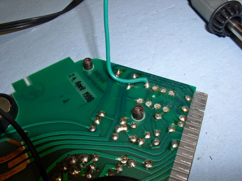
Continue soldering the remaining 5 wires to the PC board skipping pin holes #2 and #3.
I then bent and positioned the wires so they would lay flat on the PC board as Dr. Bob suggests in his write up.
Next, mark each wire to identify what pin number it is attached to on the PC board. I simply marked each wire with a number of lines representing the pin number it was soldered to using a permanent marker. By making your marks close to the end of each wire, identification will be preserved should you have to replace or resolder the new relay without having to take the head unit apart.
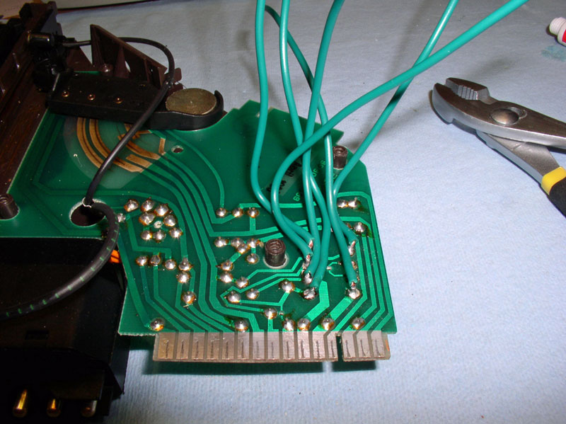
Install the back plate of the head unit and tighten the 4 screws. Ensure the wires are all laying flat against the PC board while installing the cover.
Position the top cover next.
Align the locking tabs and press the two halves together so all locking tabs are engaged.
Install the 2 screws in to the top cover.
It�s a good idea to use shrink tubing on the soldered joints to the new relay. Dr Bob recommends 3/16� shrink tubing but the closest size I had in stock was �� and it still worked fine. The tubing should be cut into lengths of approximately ��.
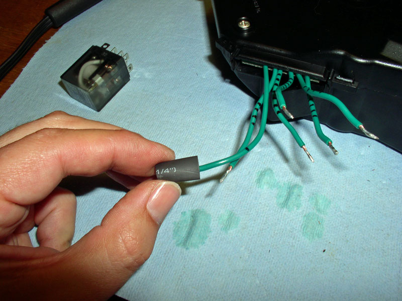
Install the shrink tubing on all 6 prepared (tinned) wire leads as shown below.
Continued....
First, I prepared the strips of 18 gauge stranded wire. I cut these to lengths of 6-7� and tinned the ends with solder. I have little to no experience with soldering but found the job is a lot easier when electrical solder flux is used. I left the opposite end unprepared since this was my first repair of this type, I thought I might need to trim the wires down further after installed. As it turns out, I did not have to trim any of the wires down so you could go ahead and strip the opposite ends of the wires and tin them as well.
I then bent each wire end that was to be soldered to the PC board at a 90 degree angle as shown.
Place the wire in the hole to be soldered as shown below. Since I�m right-handed, I found it easier to begin soldering with pin #1 as seen below then solder pin #4 next.
I bent the wire upward as shown below so that it would stay in position while I soldered it in place.
Again, be careful not to overhead the PC board when soldering. I found the soldering flux to be a big help in improving solder flow. When the soldering for the first pin is done, it should look like the picture below.
Continue soldering the remaining 5 wires to the PC board skipping pin holes #2 and #3.
I then bent and positioned the wires so they would lay flat on the PC board as Dr. Bob suggests in his write up.
Next, mark each wire to identify what pin number it is attached to on the PC board. I simply marked each wire with a number of lines representing the pin number it was soldered to using a permanent marker. By making your marks close to the end of each wire, identification will be preserved should you have to replace or resolder the new relay without having to take the head unit apart.
Install the back plate of the head unit and tighten the 4 screws. Ensure the wires are all laying flat against the PC board while installing the cover.
Position the top cover next.
Align the locking tabs and press the two halves together so all locking tabs are engaged.
Install the 2 screws in to the top cover.
It�s a good idea to use shrink tubing on the soldered joints to the new relay. Dr Bob recommends 3/16� shrink tubing but the closest size I had in stock was �� and it still worked fine. The tubing should be cut into lengths of approximately ��.
Install the shrink tubing on all 6 prepared (tinned) wire leads as shown below.
Continued....
12-31-2010, 11:39 PM
#6
Rennlist Member
Thread Starter
Join Date: Sep 2007
Location: Ridgecrest, California
Posts: 1,363
Likes: 0
Received 143 Likes
on
28 Posts
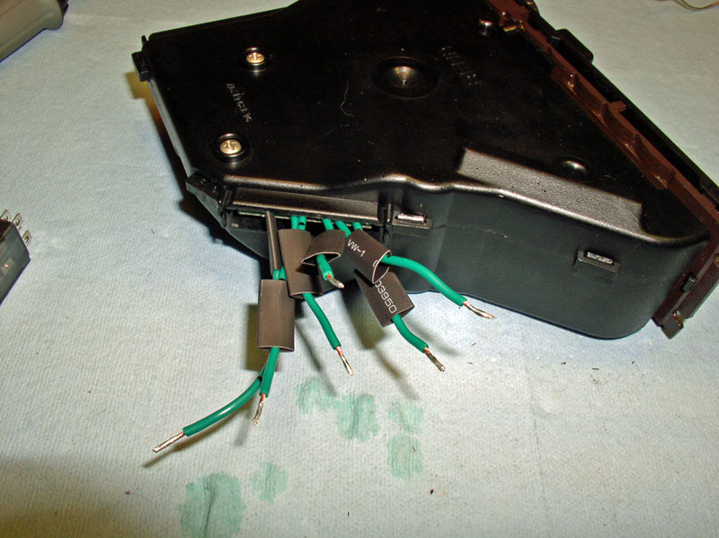
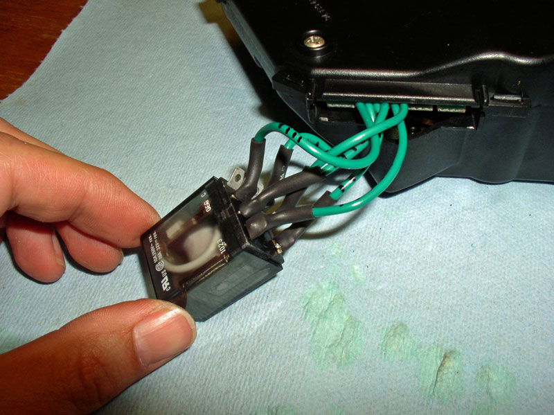
The back side of the new relay is marked with pin numbers corresponding to the schematic on the top of its case. Using the pin mapping worked out earlier, solder the corresponding wire numbers to their mapped tab on the new relay (e.g., wire #4 goes to tab #3 on the relay, wire #1 goes to tab #4 on the relay, etc.).
When all the soldering is done, slide the shrink tubing over the tab/wire soldering connections as shown below.
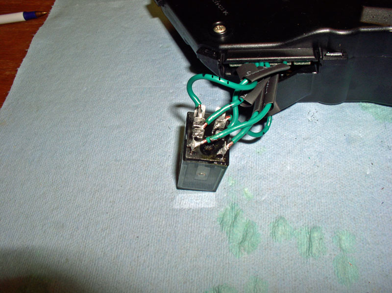
Using a heat gun or hair dryer, heat the shrink tubing.
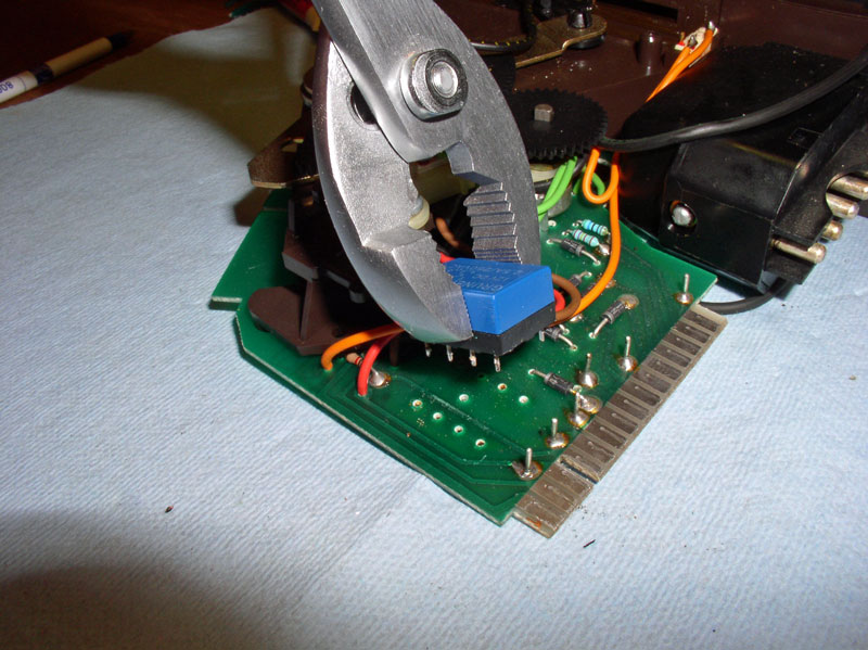
When the heating process is finished, the finished product should look like the picture below. I would recommend placing a silicone vacuum cap over the two unused tabs on the back of the relay to insulate the exposed tabs. I didn't think about this until after I had installed the unit in the center console. Next time I'm in there, I will install the caps.
I used industrial strength Velcro (extra strong adhesive) that I purchased at Home Depot for attaching the relay to the side of the head unit casing. Dr. Bob�s write up also recommends 2-sided foam tape that will work well too. You will notice a flat outcropping on the upper half of the head unit casing just above the spare port the new wires now reside that is perfectly sized to attach the relay.
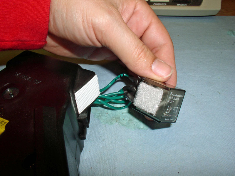
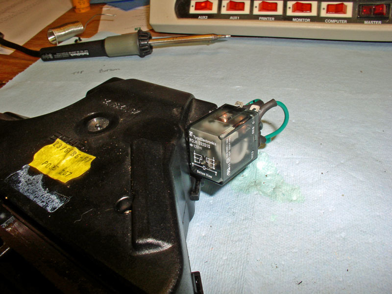
When the relay is attached, it should look something like the picture below.
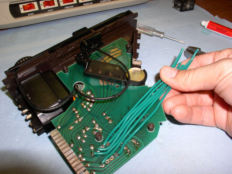
Now the head unit is ready to be re-installed in the center console. First, connect both wiring harnesses to the left side of the control unit as depicted below.
Begin positioning the head unit into the center console. Since the new relay was installed level with the head unit casing, I had no trouble sliding the unit in. Before fully installing the unit, I couldn�t wait to test it first and see if it was going to work. So I turned the key on but did not start the engine and pressed the A/C button with the lower slider not in the �off� position. I could hear and actually see the relay operate. I then checked the clutch at the compressor � ENGAGED! It worked!!
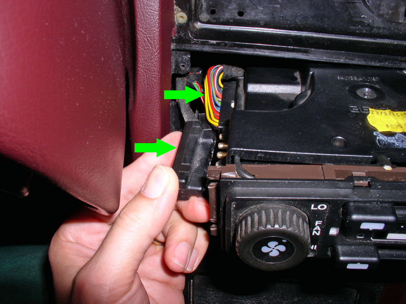
I finished pressing the control unit into place making sure it was not getting hung up on any wiring in the console. As an option, you can remove the console side cover on the right (passenger) side to monitor the re-installation of the head unit. Although it was not required, I removed it anyway because I wanted to see the clearances between the relay and the foot well vacuum actuator arm.
Re-install the A/C Button bar next.
Before tightening down the head unit, I looked at the installation from the console side cover. You can see the new relay tucked away nice and neat without any interference. Notice the Foot Well vacuum actuator arm to the right and above the relay. This is the arm�s at rest position. When in operation, the arm moves up. I tested the operation of the arm by energizing the head unit and moving the lower slider control to various positions and all worked fine.
Secure the head unit and A/C Button bar with the small screws.
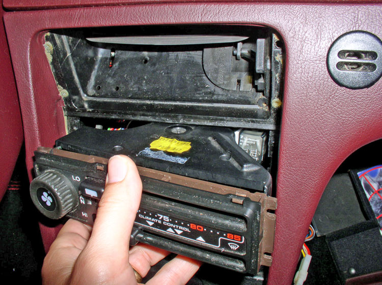
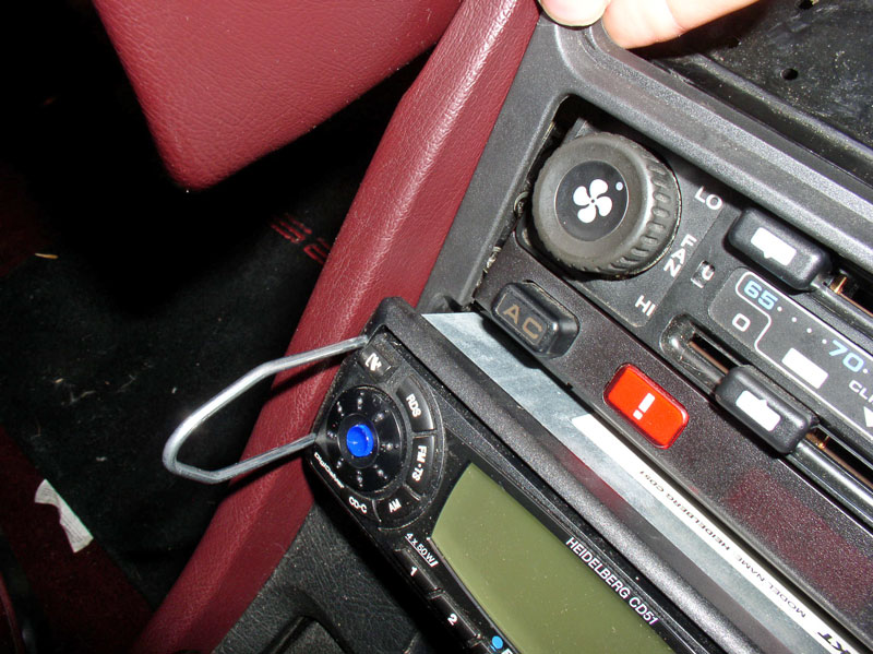
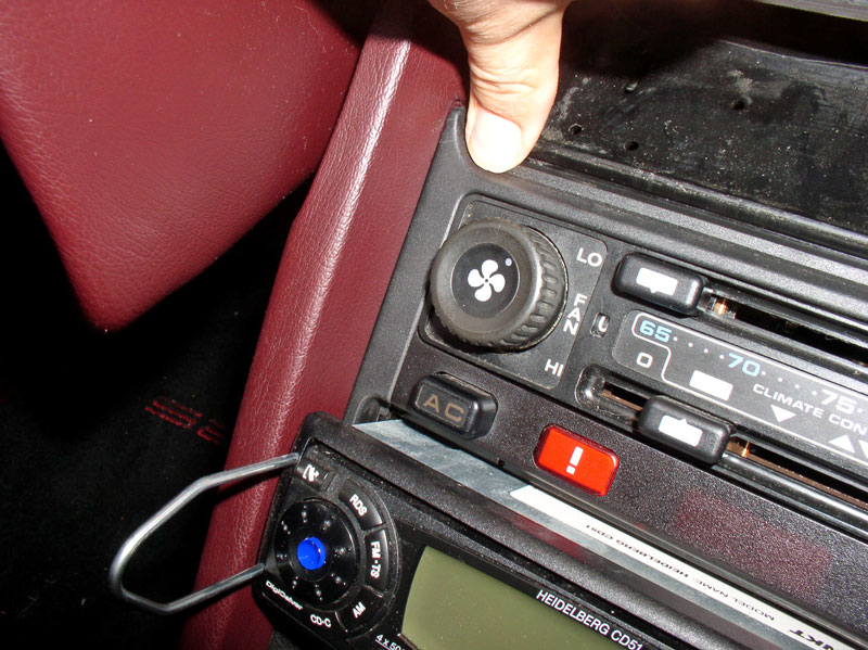
The plastic trim piece that goes around the head unit is installed next. I decided to make it a little easier to install the trim piece without risking breaking the small tabs. I installed the radio removal tool and pulled the radio forward an inch or two to provide clearance.
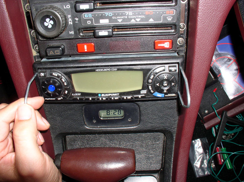
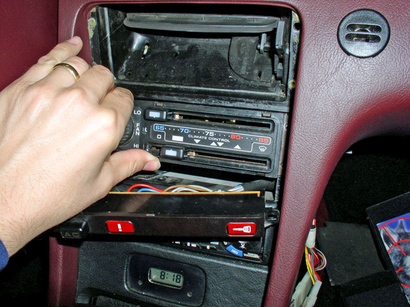
I installed one side of the trim first by pressing it into position to the right then sliding it down.
I pressed the opposite side into position next.
Continued....
When all the soldering is done, slide the shrink tubing over the tab/wire soldering connections as shown below.
Using a heat gun or hair dryer, heat the shrink tubing.
When the heating process is finished, the finished product should look like the picture below. I would recommend placing a silicone vacuum cap over the two unused tabs on the back of the relay to insulate the exposed tabs. I didn't think about this until after I had installed the unit in the center console. Next time I'm in there, I will install the caps.
I used industrial strength Velcro (extra strong adhesive) that I purchased at Home Depot for attaching the relay to the side of the head unit casing. Dr. Bob�s write up also recommends 2-sided foam tape that will work well too. You will notice a flat outcropping on the upper half of the head unit casing just above the spare port the new wires now reside that is perfectly sized to attach the relay.
When the relay is attached, it should look something like the picture below.
Now the head unit is ready to be re-installed in the center console. First, connect both wiring harnesses to the left side of the control unit as depicted below.
Begin positioning the head unit into the center console. Since the new relay was installed level with the head unit casing, I had no trouble sliding the unit in. Before fully installing the unit, I couldn�t wait to test it first and see if it was going to work. So I turned the key on but did not start the engine and pressed the A/C button with the lower slider not in the �off� position. I could hear and actually see the relay operate. I then checked the clutch at the compressor � ENGAGED! It worked!!
I finished pressing the control unit into place making sure it was not getting hung up on any wiring in the console. As an option, you can remove the console side cover on the right (passenger) side to monitor the re-installation of the head unit. Although it was not required, I removed it anyway because I wanted to see the clearances between the relay and the foot well vacuum actuator arm.
Re-install the A/C Button bar next.
Before tightening down the head unit, I looked at the installation from the console side cover. You can see the new relay tucked away nice and neat without any interference. Notice the Foot Well vacuum actuator arm to the right and above the relay. This is the arm�s at rest position. When in operation, the arm moves up. I tested the operation of the arm by energizing the head unit and moving the lower slider control to various positions and all worked fine.
Secure the head unit and A/C Button bar with the small screws.
The plastic trim piece that goes around the head unit is installed next. I decided to make it a little easier to install the trim piece without risking breaking the small tabs. I installed the radio removal tool and pulled the radio forward an inch or two to provide clearance.
I installed one side of the trim first by pressing it into position to the right then sliding it down.
I pressed the opposite side into position next.
Continued....
12-31-2010, 11:49 PM
#7
Rennlist Member
Thread Starter
Join Date: Sep 2007
Location: Ridgecrest, California
Posts: 1,363
Likes: 0
Received 143 Likes
on
28 Posts
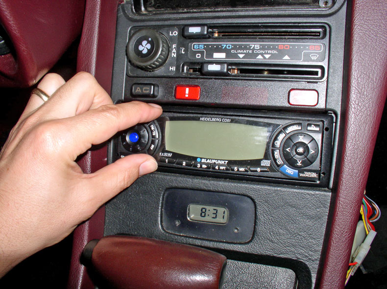
When installed, it should look like the picture below.
I then pressed the radio back into position.
Position the center vent for re-installation lining up the plastic pin tabs on the vent with their respective holes in the center console. This took a little maneuvering to feel all 4 tabs find their hole then press it into place. I found it easier to install the vent with the flap control centered at mid position as pictured below.
This completes the interior install. You can test the head unit operation once again now that it�s secured. Re-install the console side cover if you removed it.
Since we replaced the smaller relay with a much beefier one rated at 10A which is much higher than the original 2.5A relay and the fact that the A/C compressor coil circuit is unfused between the HVAC head unit and the compressor, we must insert an inline fuse. The inline fuse will prevent circuit overload and the possibility of fire. The fuse will be inserted on the power line going into the freeze switch (this is a direct line from the HVAC head unit from the new relay). The recommended amperage of the inline fuse is 3A. I�d like to thank Greg Brown (GregBBRD on Rennlist) for this important addition and added protection from possible fire � THANKS, Greg!
I purchased a standard, already wired inline fuse from O�Reilly�s Auto Parts Store that had a cover. It was about $4. I put a �� male spade connector on one end of the wire and a �� female protected spade connector on the other end and crimped them into place as shown in the pic below.
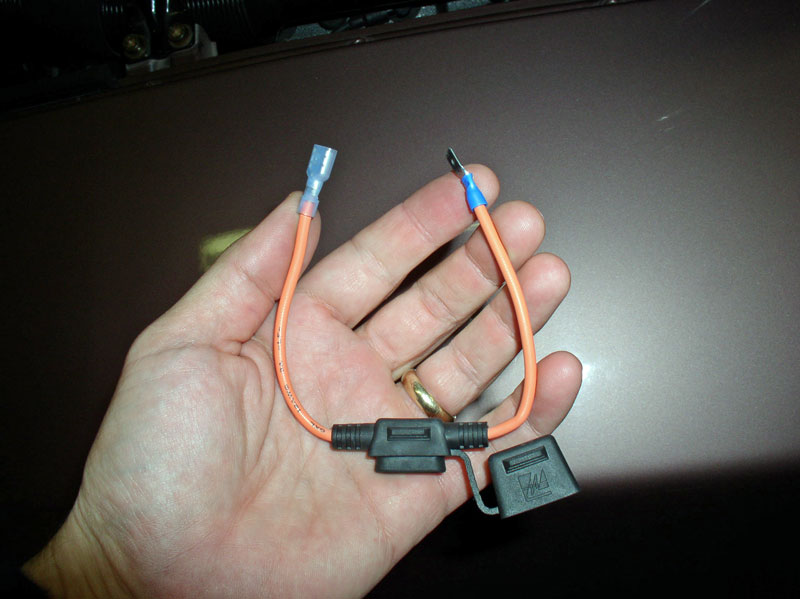
I inserted a standard 3A fuse.
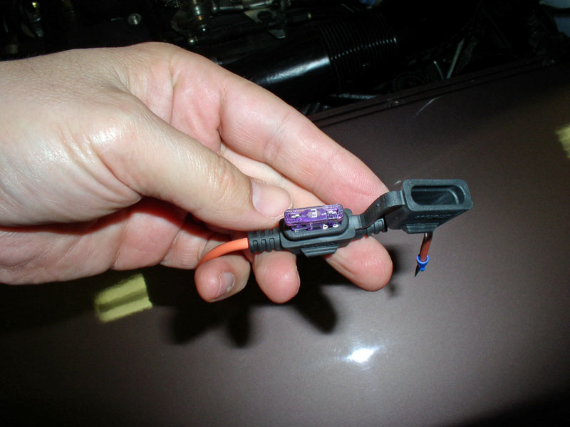
Then disconnect the 2-wire power line from the freeze switch and insert the male connector all the way in so no metal is exposed. For added protection, you can slide a �� length of heat shrink tubing over the connection and �shrink� it down with a heat gun.
Slide the protected female connector on the freeze switch terminal.
Place the cap on the fuse and tuck the wires away.
Ensure all jumpers are removed and replace the plastic rain cover.
CONGRATULATIONS! You�ve completed the HVAC compressor relay repair and should be able to enjoy cold air once again!!
I�d like to thank Dr Bob and Louis Ott for their documented descriptions that made this repair go silky smooth � THANKS! Here is a link to Dr Bob�s original write up that is available on the Nichols Site: http://www.nichols.nu/tip055.htm. I�d also like to thank Greg Brown for the recommendation to add the 3A fuse to the compressor circuit � THANKS!
This was my first experience with this type of repair and, as always, I welcome comments and recommendations to improve the quality of this post. THANKS for reading!
I then pressed the radio back into position.
Position the center vent for re-installation lining up the plastic pin tabs on the vent with their respective holes in the center console. This took a little maneuvering to feel all 4 tabs find their hole then press it into place. I found it easier to install the vent with the flap control centered at mid position as pictured below.
This completes the interior install. You can test the head unit operation once again now that it�s secured. Re-install the console side cover if you removed it.
Since we replaced the smaller relay with a much beefier one rated at 10A which is much higher than the original 2.5A relay and the fact that the A/C compressor coil circuit is unfused between the HVAC head unit and the compressor, we must insert an inline fuse. The inline fuse will prevent circuit overload and the possibility of fire. The fuse will be inserted on the power line going into the freeze switch (this is a direct line from the HVAC head unit from the new relay). The recommended amperage of the inline fuse is 3A. I�d like to thank Greg Brown (GregBBRD on Rennlist) for this important addition and added protection from possible fire � THANKS, Greg!
I purchased a standard, already wired inline fuse from O�Reilly�s Auto Parts Store that had a cover. It was about $4. I put a �� male spade connector on one end of the wire and a �� female protected spade connector on the other end and crimped them into place as shown in the pic below.
I inserted a standard 3A fuse.
Then disconnect the 2-wire power line from the freeze switch and insert the male connector all the way in so no metal is exposed. For added protection, you can slide a �� length of heat shrink tubing over the connection and �shrink� it down with a heat gun.
Slide the protected female connector on the freeze switch terminal.
Place the cap on the fuse and tuck the wires away.
Ensure all jumpers are removed and replace the plastic rain cover.
CONGRATULATIONS! You�ve completed the HVAC compressor relay repair and should be able to enjoy cold air once again!!
I�d like to thank Dr Bob and Louis Ott for their documented descriptions that made this repair go silky smooth � THANKS! Here is a link to Dr Bob�s original write up that is available on the Nichols Site: http://www.nichols.nu/tip055.htm. I�d also like to thank Greg Brown for the recommendation to add the 3A fuse to the compressor circuit � THANKS!
This was my first experience with this type of repair and, as always, I welcome comments and recommendations to improve the quality of this post. THANKS for reading!
Last edited by Dwayne; 01-03-2011 at 10:12 PM.
Trending Topics

 01-01-2011, 12:48 PM
#9
Rennlist Member
Another great write up Dwayne...........well done.
If I may some tips on soldering:
the PCB used in the HVAC head is very basic through hole technology and when the assembly was built at factory the components were mounted on one side of the board then ran through a solder bath at such a level that only the bottom side of the board and the legs of the through hole components touched the molten solder. The solder is then drawn up the legs of the components with capillary action leaving all perfectly soldered.
This action can be replicated by the home mechanic by soldering from the bottom side of the PCB allowing the solder to be drawn up each individual wire by using Dwaynes method above and bending the tinned wire to secure it to the PCB. Once all wires are soldered then, if required, clip off any excess.
Last edited by the flyin' scotsman; 01-01-2011 at 04:17 PM.
01-01-2011, 12:53 PM
#10
Drifting

Dwayne,
Glad you got it done.
As you know, internal relay is a DPDT, but only used as a DPST. It is switching two signals at the same time. You can see this from the WSM wiring diagrams, those two signals go externally on a smaller (0.5) wire for one switch and larger (1.0) wire the other. So one side of the relay is switching low current, and the other high current.
Based on this, another approach would be to install two SPST minature relays (one high current, the other low current). These are small enough that they could be both mounted inside the control unit.
From Radio Shack .... here's a minature 12 volt SPST rated at 10 amps...
http://www.radioshack.com/product/in...lterValue=SPDT
And this SPDT minature rated at 1 amp...
http://www.radioshack.com/product/in...lterValue=SPDT
Or, you could be able to get by with a single 5 amp minature like this...
http://www.radioshack.com/product/in...lterValue=DPDT
01-01-2011, 03:24 PM
#11
Racer
Join Date: Dec 2009
Location: The Netherlands, Zuid Beijerland
Posts: 278
Likes: 0
Received 0 Likes
on
0 Posts
Dwayne, you are an inspiration to all of us. What an excellent documentary again! Your other write up and pictures on the pod removal procedure and speedo repair kept me going and feeling confident I could tackle the issues myself. And it all works again. Many thanks!
Leo, 1984 Euro S2 manual
Leo, 1984 Euro S2 manual
01-01-2011, 03:50 PM
#12
Rennlist Member
Excellent writeup!
One thing to note, on OBs the AC compressor clutch will never engage unless the engine is running, assuming the wiring has not been altered. These cars have a special "speed relay"(XI on CE panel) that won't engage unless it sees a tach signal. So, to troubleshoot AC on an OB you need to jumper this relay then go through steps in the writeup above. 1980 and later work essentially as described in Dwayne's writeup.
For my OB I added a power relay to the CE panel to serve the purpose of the relay that Dwayne added above(also to take the load off of the speed relay), details here.
01-01-2011, 07:34 PM
#14
Rennlist
Basic Site Sponsor
Basic Site Sponsor
A couple of thoughts....
Note that the stock relay and wiring to the compressor, is an unfused circuit, in the 928 vehicle. The relative "weakness" of the original relay saves the relay board and wiring, in the vehicle, from severe electrical damage (fire).
Adding a huge relay, such as this, will certainly eliminate the problem with the relay failing...but if anything ever goes wrong....plan on a fire, instead of relay failure.
Most of the relay failures are actually a result of the resistance in the circuit increasing, with age. Any place that either the loom deterorates or if the compressor clutch resistance increases will increase the current through the relay and cause failure....of the stock unit. Significantly increasing the amperage rating of the relay, without regard to this circuit, will significantly increase the likelyhood of a fire.
We rebuilt many of these control units (928 International has them). Although we do use a higher amperage relay, we do add a protection fuse to this circuit....which has reduced the "comeback" of rebuilt units to almost zero (0). We also found that the A/C control units had "other issues" than just the failure of the relay. We built "test boards" to completely test each unit, before and after repairs. Prior to the addition of the new fuse, many of the rebuilt control units came back with the new relays melted....the result of a problem on the circuit to the compressor. Now that the circuit is fused, when there is a problem, the fuse will blow, instead of the relay failing.
__________________
greg brown

714 879 9072
GregBBRD@aol.com
Semi-retired, as of Feb 1, 2023.
The days of free technical advice are over.
Free consultations will no longer be available.
Will still be in the shop, isolated and exclusively working on project cars, developmental work and products, engines and transmissions.
Have fun with your 928's people!
greg brown
714 879 9072
GregBBRD@aol.com
Semi-retired, as of Feb 1, 2023.
The days of free technical advice are over.
Free consultations will no longer be available.
Will still be in the shop, isolated and exclusively working on project cars, developmental work and products, engines and transmissions.
Have fun with your 928's people!
01-01-2011, 08:01 PM
#15
Rennlist Member
It turns out that the circuit is fused on the OBs, fuse #17. I rewired mine so that the current for the clutch does not go through the speed relay; the only load on the speed relay is the coil on the power relay. The power relay switches current from fuse #17 to the AC clutch, just as Hans & Franz intended. Not sure why they would have gone to an unfused circuit in the '80 and later cars -- seems kind of stupid. Good call adding fuses to your retrofits.

