
Awesome and/or crazy turbo project. You pick.

 01-08-2016, 01:41 PM
#107
Archive Gatekeeper
Rennlist Member
Rennlist Member
Will there be hood vents of some sort so the lighting is apparent in people's rear view mirrors, so they get to have a "WTF is that?" moment before you pass them? 
01-08-2016, 02:43 PM
#110
Racer
Thread Starter
Join Date: Apr 2009
Location: Indianapolis
Posts: 288
Likes: 0
Received 0 Likes
on
0 Posts
01-08-2016, 02:45 PM
#111
Racer
Thread Starter
Join Date: Apr 2009
Location: Indianapolis
Posts: 288
Likes: 0
Received 0 Likes
on
0 Posts
I really have no idea what I'm doing about the hood yet. I can tell you I have two Tial wastegates and the top of them and the screamer pipes are going right out the top...less heat in the engine bay right!?
01-08-2016, 02:46 PM
#112
Racer
Thread Starter
Join Date: Apr 2009
Location: Indianapolis
Posts: 288
Likes: 0
Received 0 Likes
on
0 Posts
01-09-2016, 12:55 PM
#113
Rennlist Member

 01-09-2016, 01:00 PM
#114
Rennlist Member
01-11-2016, 03:15 AM
#115
Pro
Really nice! The two intakes is the same design as I have been dreaming about! The difference is that I was planning to put a Lysholm AX3300 in the valley with a A/A intercooler in the front. I even dreamed of using glass, but over the supercharger outlet. I have not done anything for years, maybe when the kids grow up...
Another thing I dreamed up once (then for my girlfriends Porsche 951), is the possibility to swap the heads around, this would place the exhaust ports inside the valley and the intake ports on the outside. I am not sure if this would be a benefit for you when I see that turbo inside there but the runners sure would be short! The timing belt would be a challenge, but the biggest problem is the oil drain. Maybe you could just drain oil into the V and use a dry sump pump...") Or do it the american way and just let the oil drain onto the crank...
Or do it the american way and just let the oil drain onto the crank...
Another thing I dreamed up once (then for my girlfriends Porsche 951), is the possibility to swap the heads around, this would place the exhaust ports inside the valley and the intake ports on the outside. I am not sure if this would be a benefit for you when I see that turbo inside there but the runners sure would be short! The timing belt would be a challenge, but the biggest problem is the oil drain. Maybe you could just drain oil into the V and use a dry sump pump...
Or do it the american way and just let the oil drain onto the crank...
01-11-2016, 09:57 AM
#116
Racer
Thread Starter
Join Date: Apr 2009
Location: Indianapolis
Posts: 288
Likes: 0
Received 0 Likes
on
0 Posts
The amount of oil draining out of the turbocharger is really pretty insignificant. I can't imagine it draining in the valley over one of the mains making a tangible difference in windage or anything else with the volume that exits the crankshafts bearings already...not to mention the oil returning from the heads getting in the mix as well.
Talking about turning the heads around is funny, like how the newer BMW v8's work. I've seen some Suzuki funnybikes flow through the heads backwards (using the opposite ports). When a turbo motor starts getting really serious, getting exhaust out is a major issue. The old saying about the exhaust ports flowing 80% of the intake no longer is entirely accurate. Flow needs to be closer to equal because the hot exhaust gases when burning such a high quantity of fuel/air are hard to get out and have more volume than the intake. On some of the over 1000hp 4g63 engines I've read about, when people have trouble keeping heads sealed one answer that seams to help is running a bigger exhaust cam profile than intake to help the motor blow down more easily, again against conventional wisdom.
Talking about turning the heads around is funny, like how the newer BMW v8's work. I've seen some Suzuki funnybikes flow through the heads backwards (using the opposite ports). When a turbo motor starts getting really serious, getting exhaust out is a major issue. The old saying about the exhaust ports flowing 80% of the intake no longer is entirely accurate. Flow needs to be closer to equal because the hot exhaust gases when burning such a high quantity of fuel/air are hard to get out and have more volume than the intake. On some of the over 1000hp 4g63 engines I've read about, when people have trouble keeping heads sealed one answer that seams to help is running a bigger exhaust cam profile than intake to help the motor blow down more easily, again against conventional wisdom.
 02-17-2016, 12:46 AM
#118
Racer
Thread Starter
Join Date: Apr 2009
Location: Indianapolis
Posts: 288
Likes: 0
Received 0 Likes
on
0 Posts
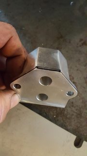
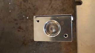
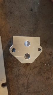
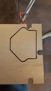
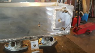
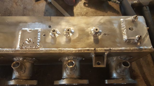
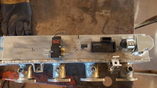
The hole furthest from the valve isn't used. I'm taking air in at the front. A large nipple (!!!) will connect it to another one on the intercooler pipe just ahead of the throttle body. I'm intentionally admitting air to the passenger manifold only...the crossover pipe between the manifolds will likely be at the rear (somewhat near the hot exhaust area). If their is any heat soak at idle I thought a little airflow from the passenger to driver manifold would help keep the crossover pipe a little cooler, not that it matters a lot.
02-17-2016, 12:53 AM
#119
Racer
Thread Starter
Join Date: Apr 2009
Location: Indianapolis
Posts: 288
Likes: 0
Received 0 Likes
on
0 Posts
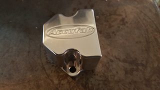
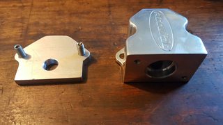
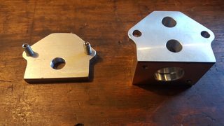
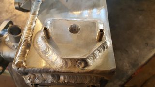
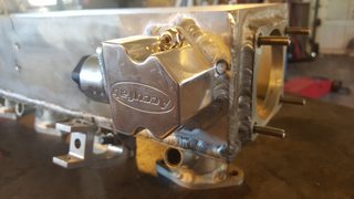
So much for the pretty finish...
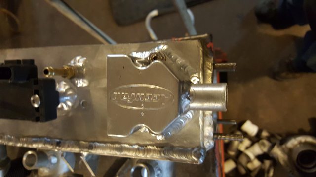
I also started doing the mounts for boost control solenoid (4 port MAC valve - high temperature and high frequency for a big range of boost), the 3 bar map sensor, nipples for the map, BOV, and FPR. This picture is just before I got done. I've been trying really hard not to drill holes through to the inside for bolts because I don't want to clutter up the view inside with the trumpets and lighting. I also prefer not to mount anything more than necessary on the inside edge of the intakes. If, for some reason, I can't electronically smooth out the signal from the map sensor by a weird resonance, I left space to install a small inline filter in the vacuum line to the map to dampen it out. With the huge plenum volumes I have, plus a crossover tube, I highly doubt that will matter...just trying to plan for what eventualities I can.
I also started doing the mounts for boost control solenoid (4 port MAC valve - high temperature and high frequency for a big range of boost), the 3 bar map sensor, nipples for the map, BOV, and FPR. This picture is just before I got done. I've been trying really hard not to drill holes through to the inside for bolts because I don't want to clutter up the view inside with the trumpets and lighting. I also prefer not to mount anything more than necessary on the inside edge of the intakes. If, for some reason, I can't electronically smooth out the signal from the map sensor by a weird resonance, I left space to install a small inline filter in the vacuum line to the map to dampen it out. With the huge plenum volumes I have, plus a crossover tube, I highly doubt that will matter...just trying to plan for what eventualities I can.
02-17-2016, 01:20 AM
#120
Racer
Thread Starter
Join Date: Apr 2009
Location: Indianapolis
Posts: 288
Likes: 0
Received 0 Likes
on
0 Posts
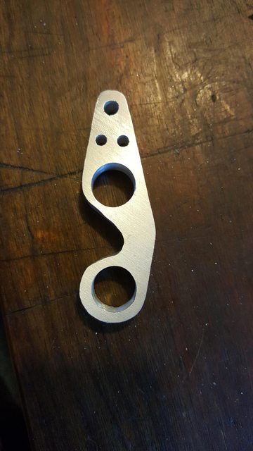
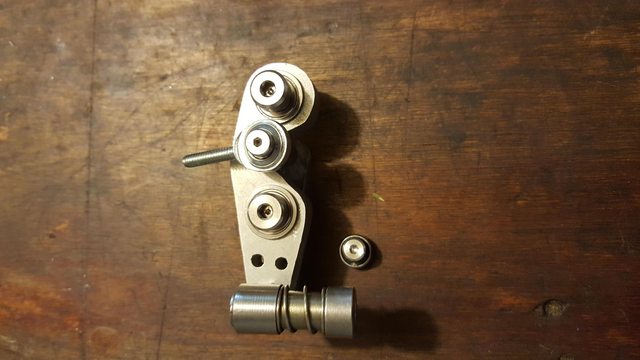
I also started designing custom throttle linkage. This is a little hard to follow without a finished project to show. The original cable attaches to the driver side, of the driver side intake plenum (between it and the shock tower if you will). It attaches to a progressive linkage, then will go to a vertical turning piece that functions like a cantilever I suppose, then from the cantilever to the top of the driver side throttle, then on to the passenger throttle. The function of the cantilever is to get the linkage from the progressive assembly to the top of the throttle. The linkage would have to pass right through the corner of the manifold, so the "turny" cantilever piece is necessary. The throttle cable attaches to the quick release ball stud, and the heim joint heads to the cantilever.
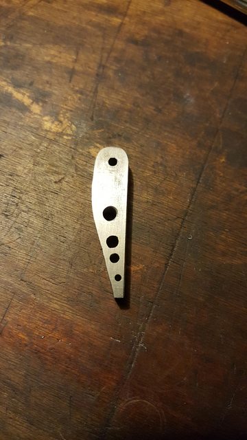
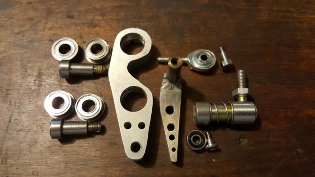
I should also explain this: My engine now has two throttle bodies, each of which is at least the size of the original single one I already had. When you have a lot of throttle body in relation to your engine the throttle can become way overly sensitive, or "touchy", if you will. I don't want it to be difficult to regulate the throttle at low speeds or when leaving a stop (5 speed). I designed the progressive part of the linkage so the throttles will open only 20% when the accelerator pedal is down 50%. After that the rear piece catches a bearing and speeds up a lot. As you will see the small rear bearing has three mounting locations to adjust when the output arm catches and how fast it responds, but is designed so the throttles will be open 100% when the accelerator is 100% regardless of which of the three spots it is in. Hope that makes sense.
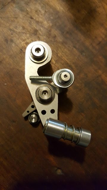
Lots of materials are going on here. The front piece is 6061-t6 aluminum. The bearings and hardware are stainless. The rear arm is high carbon steel because it contacts the bearing and might get an impression over time, plus it accepts the threads from the bearing screw. The little stud sticking up from the rear arm for the heim joint to attach to is stainless. In the next post the stud the entire assembly bolts to (the screw at the top goes in to it) is made from a grade 8 bolt I cut down, drilled, and threaded. Such a P.I.T.A. drilling and tapping hardened steel.
Finally, and most importantly, I did all this with a band saw, drill press, and a sander. I have way too much time...
I should also explain this: My engine now has two throttle bodies, each of which is at least the size of the original single one I already had. When you have a lot of throttle body in relation to your engine the throttle can become way overly sensitive, or "touchy", if you will. I don't want it to be difficult to regulate the throttle at low speeds or when leaving a stop (5 speed). I designed the progressive part of the linkage so the throttles will open only 20% when the accelerator pedal is down 50%. After that the rear piece catches a bearing and speeds up a lot. As you will see the small rear bearing has three mounting locations to adjust when the output arm catches and how fast it responds, but is designed so the throttles will be open 100% when the accelerator is 100% regardless of which of the three spots it is in. Hope that makes sense.
Lots of materials are going on here. The front piece is 6061-t6 aluminum. The bearings and hardware are stainless. The rear arm is high carbon steel because it contacts the bearing and might get an impression over time, plus it accepts the threads from the bearing screw. The little stud sticking up from the rear arm for the heim joint to attach to is stainless. In the next post the stud the entire assembly bolts to (the screw at the top goes in to it) is made from a grade 8 bolt I cut down, drilled, and threaded. Such a P.I.T.A. drilling and tapping hardened steel.
Finally, and most importantly, I did all this with a band saw, drill press, and a sander. I have way too much time...
Last edited by entropy_engineering; 02-17-2016 at 01:54 AM.