
Throttle body support stud
 07-17-2014, 06:21 AM
#1
928 Barrister
Rennlist Member
Rennlist Member
Thread Starter
The throttle body on my '86.5 is held down in four places (it seems). One at the front centerline, one at the rear centerline, and one each on each side. The side ones are held in place by epoxy or some other adhesive which is applied to a support on the engine block in the valley. This arrangement seems strange to me because the support projection of the engine block seems like it could benefit from the installation of a time sert or helicoil insert into which the stud securing the throttle body could be screwed. But on my car, that stud is glued to that **** or projection from the engine block, and the adhesive failed. I have the stud, with a flexible round base but tried to epoxy it back into place. Of course it failed and broke loose when I bolted the TB to the block.
My question is: can I safely tap that **** or protrusion from the block and install an insert there so I can screw the stud holding the TB into it? Or would I compromise the engine case by screwing anything into it at that point?
The photo I've posted shows the throttle body part that is held by the bolt in question. It is circled by a dashed line in the photo.
Has anyone encountered this problem on their car? If you have, and have found another way to solve this problem, please share. Thank you.
 07-17-2014, 08:51 AM
#4
Rennlist Member
.. and here are a couple of pics of what happens to them. They are effectively just two button headed studs, with rubber bonded between them. When they deteriorate the rubber disintegrates, and leaves one of the button headed studs behind in the block. To get that stud out use some penetrant to help ease it out first, then try grabbing the head with vice grips. If no success that way, try cutting a screwdriver slot in it with a hacksaw blade to get it out.
The first pic (from an older car) shows what gets left behind on the body, sometimes with no rubber at all; and the second is what is left screwed into the block, that you have to get out.
The first pic (from an older car) shows what gets left behind on the body, sometimes with no rubber at all; and the second is what is left screwed into the block, that you have to get out.
 07-17-2014, 10:12 AM
#6
Craic Head
Lifetime Rennlist
Member
Lifetime Rennlist
Member
Also, they are not all the same. I think there are three of them holding the lower air guide?
There are two part numbers. I think #23 is the one that also secures the ISV and is longer on one end. #27 isn't the same and I thought there was another one down there, but I can't remember now.
+1 Roger's got 'em.
There are two part numbers. I think #23 is the one that also secures the ISV and is longer on one end. #27 isn't the same and I thought there was another one down there, but I can't remember now.
+1 Roger's got 'em.
07-17-2014, 10:49 AM
#7
Man of many SIGs
Rennlist Member
Rennlist Member
Most likely your rubber has come off of the steel. The vulcanization didn't seem to hold up too well over the years of heat cycling. Luckily they are easy to remove and cheap to replace. Take a center punch and a hammer and use it to strike the flat round top of the stud that's left in the engine block in a counter clockwise motion and you can unscrew it. I believe the ones Roger sells are not direct replacements. The threaded stud is longer than stock and you have to trim them to match. They are less expensive so that's why he stocks them. I'm sure he can get the original ones from Porsche as well if you prefer.
Trending Topics
07-17-2014, 01:13 PM
#9
Inventor
Rennlist Member
Rennlist Member
Don't be surprised if it the TB housing is difficult to install with the new isolators.
The housing has to line up just right.
The housing has to line up just right.
07-17-2014, 07:37 PM
#10
928 Barrister
Rennlist Member
Rennlist Member
Thread Starter
Thank you to everyone who has contributed to answering this question.
I must point out that my isolating stud doesn't have a threaded rod on the bottom like is shown in Dave's PET illustration as part number 23. Mine has only the threaded portion above the rubber isolation part and appeared to be bonded to the aluminum nub on the engine block. The isolation stud shown in the Pet illustration is like the one that holds down my air filter housing on both sides.
I have sketched how the isolator appears below. The only way I can imagine to restore attachment to the engine block is to drill into the nub projecting from the valley wall and insert a helicoil insert into it and then use the kind of isolator shown in Dave's Pet illustration. I fear that because I am not familiar with 928 engine cases and wonder if I might hit something the factory didn't want disturbed.
07-18-2014, 01:01 AM
#11
Addict extrordinare
Rennlist Member
Rennlist Member
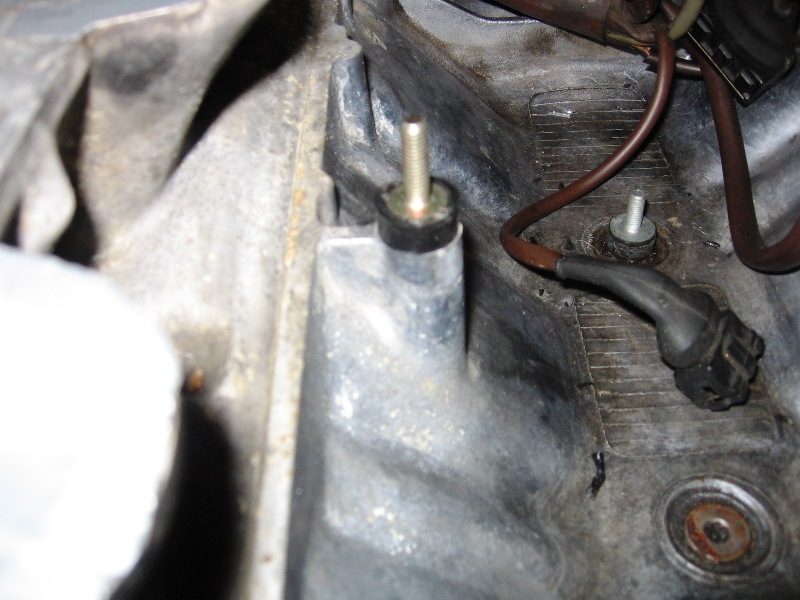
Have you already removed the bottom part of the mount? Can you post a picture of what it looks like now? There are only three mounts. Two forward and one aft. It sounds like you have the bottom half of the isolator still screwed in as in the picture below. If so, you need to get a hold of it and unscrew it. Sometimes it works well and others it doesn't. I was able to cure one of mine that didn't with a dremel.
07-18-2014, 01:31 AM
#12
Addict extrordinare
Rennlist Member
Rennlist Member
This is what it looks like installed.
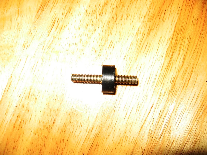
This is what the mount looks like. Notice that one side is longer than the other. It's needed to go through the bracket for the idle air control.
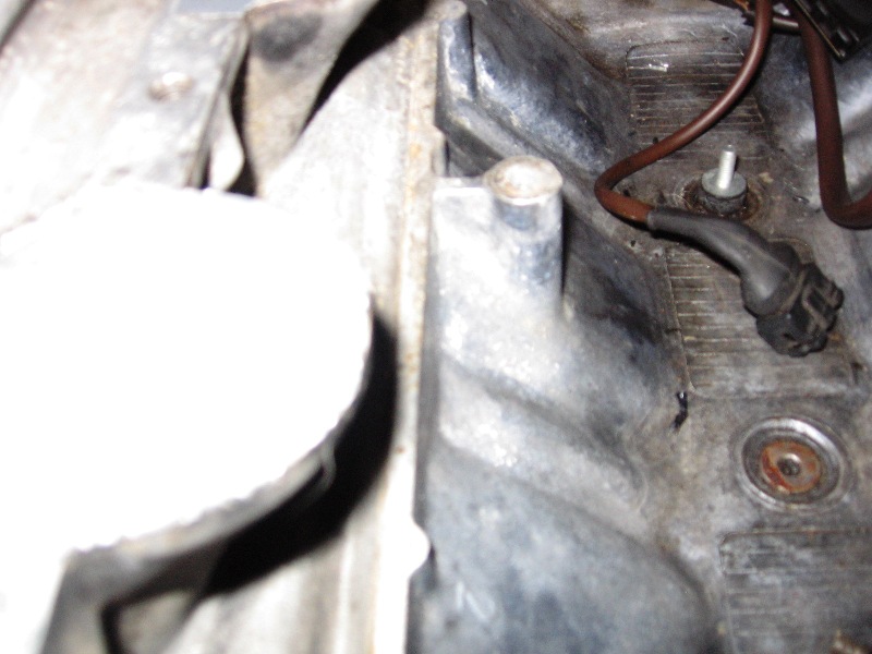
Here's what the mount on the block looks like. Sorry for the crappy quality of the pictures. This is the isolator mount that I had to grind out. It wasn't that bad though. Show us some picutes of what you have.
This is what the mount looks like. Notice that one side is longer than the other. It's needed to go through the bracket for the idle air control.
Here's what the mount on the block looks like. Sorry for the crappy quality of the pictures. This is the isolator mount that I had to grind out. It wasn't that bad though. Show us some picutes of what you have.
07-18-2014, 02:24 AM
#13
928 Barrister
Rennlist Member
Rennlist Member
Thread Starter
Thank you Ethan. I think you hit it correctly by saying the top half broke off of the bottom half. My idle air control side seemed to have only the top stud attached to the rubber part and no other metal. That leads me to believe the lower half with the metal disc still attached is still screwed into the block. It didn't appear to be that way, but that's the only logical explanation. I put it all back together using some off brand epoxy I had around (ran out of JB Weld) and the next day tried to tighten it. Of course the stud broke loose when the epoxy failed. I haven't gone back in there recently because I've been too busy with work. Next weekend I will go exploring to find the lower half screwed into the block and get it out. I have some new isolators I got from Roger (I bought extra for this kind of situation). If what you describe is the case, and I think it must be, I'll be in luck. I have a mini Dremel that will allow me to cut a groove in the metal disc and unscrew the half isolator still in the block.
All of this came about because I wanted to change my
throttle position sensor and it seems I must get the throttle body out of the valley to allow access to the bottom screw holding it to the throttle body. Right now, the entire intake system is installed so I must remove it all again.
I just never inspected the base of the isolator to confirm that there was another threaded end remaining in the block. Thanks again. The photos help a great deal, especially the first photo. That is what is probably remaining in the block and it appeared to me that
the upper part of the isolator had been epoxied to the block and had broken off, when in reality, it had merely broken the bond between that part and the rubber top part of the isolator, as Fabio described. Now I know the isolator screws into the block and I don't have to tap it to install another isolator. Whew! I'll be in there and out in a jiffy.
Last edited by Ron_H; 07-18-2014 at 02:39 AM. Reason: add text
07-18-2014, 04:16 AM
#14
Rennlist Member
If all goes well you will ... but to be sure, get some penetrating oil in that area, well before you try to get it out, it'll make it much easier. See how the thread on the button headed stud is rusted, on both the pic I posted and also Snozs .. which makes them seize.
Snoz must have used vice grips to get his out, because you can see the marks on the edge of the button headed stud. Hopefully that'll work for you, but if not grind/cut a slot in the top. That one I posted a pic of came out easily without tools, and hasn't got any marks or slots on it, because it had been soaked in penetrant.
When you remove your throttle body you should see the button, with the ring marks on it, just like in my second pic, which is what you have to grab to get the stud out.
07-18-2014, 04:24 AM
#15
928 Barrister
Rennlist Member
Rennlist Member
Thread Starter
Thanks. I will soak the stud in some penetrating oil before attempting to remove it. A few more hours won't make a difference.