When you click on links to various merchants on this site and make a purchase, this can result in this site earning a commission. Affiliate programs and affiliations include, but are not limited to, the eBay Partner Network.
To remove one of the standoffs on my '86.5 I used a dremmel to slot the piece then used a hammer and extractor to loosen screw. It then came out easily.
Two part numbers is correct, the one on Dans' driver side, (passenger side in the US) has a longer stud sticking up to mount the Idle control valve on top of the air guide, without the longer stud it is very hard to find sufficient threads to get the nut in place.
ok, so i've searched, i've ordered, i've bought, i've searched again and i'm pretty sure i've now got it straight.
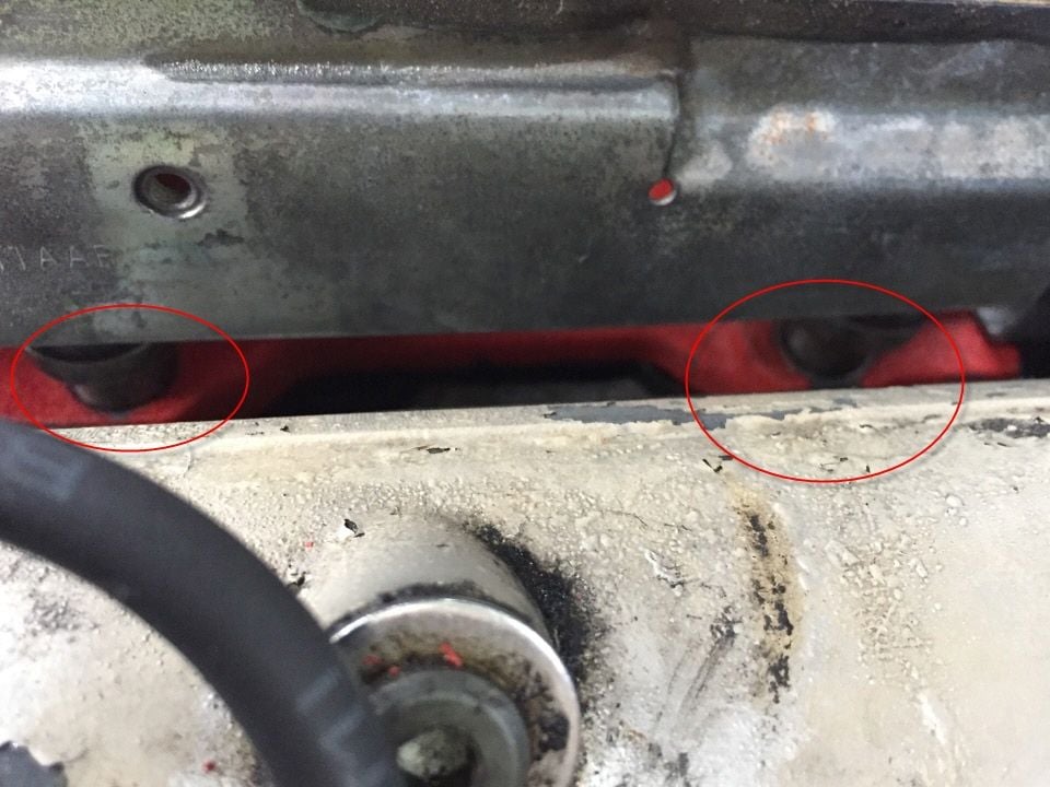
There are two standoffs you need to seat a 1985-86 (as pointed out by Shane).
There are three different ones on the market that you may be told u need depending on who you talk to....
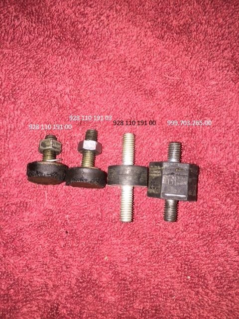
Below is a picture of the ones i currently have in my possession.
What i would say is that if you are trying to bolt an air guide to the motor, you only need two of the three below (928 110 191 00 & 928 110 191 03)
(23)
928 110 191 00 - These are good, put em on your rear and left hand side mounts
928 110 191 03 - this one is also good, put it on your right hand side, underneath your idle control valve (with the extra thread length being helpful)
(27)
999.703.265.00 - WTF - dunno what its for, but not for the air guide
930.110.579.01 - WTF - dunno what its for, but not for the air guide
I am yet t be able to find a 928 110 191 03 in aus (with the extra thread length), but i think i'll just make my own rather than wait 3 weeks for an import from the states.
I hope this helps any who come behind me looking for these parts.
Dan
Tried to get those three standoffs out today with only mixed success.
The first two came off easily after grooving and then tapping with a chisel as was previously suggested. Nice.
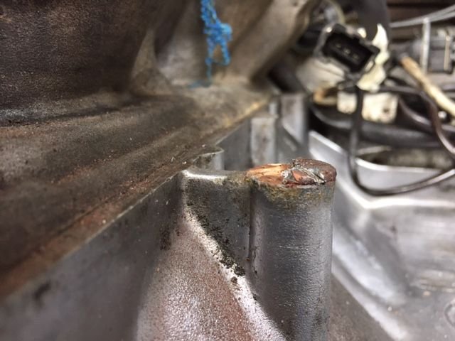
The third one was jammed in there tight and wouldn't respond to either chisel or grooving deeply enough to get a screw driver in it....damn damn damn. Got the metal cap off but the thread was still glued in there.
Eventually i got the drill out and made a hole, then went in with a screw extractor.....which SNAPPED OFF in there. About this time i was wondering what the hell i was getting myself in to.
Anyway, managed to get the extractor out with a bit more drilling with a tiny bit, and then just drilled the rest of the bolt out. Then i ran a threading tap in there to re-thread the hole.
Anyway, it's back in now, and the air guide is bolted down.
PS - i had a change of heart this morning and decided not to use the Porsche standoffs after all. My guess is that rubber would just break down again in pretty short order.
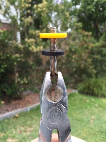
Instead I bought long threaded bolts, cut the heads off them and have thrown a couple of thick nylon washers (tap washers) on them to keep the standoff effect and vibration absorption which i'm guessing is the purpose of these peices. They are now just a single bolt holding the air guide onto the engine.
Does anyone see weaknesses in that design?
Will let you know if a few years how well they have held up.
Just make sure that the air guide sits at the same height as with the stock pieces or it can cause alignment problems with the "T" that sits atop the throttle body. Just make sure the washers are the same thickness as the rubber standoff and that they fit into the recesses on the bottom side of the air guide.
One consideration is that your current method will likely pass more engine vibration through your single bolts into the air guide and by association into the MAF.
The OE system specifically avoided having one solid metal vibration path going from the engine block into the air guide and then MAF. By using one solid metal shaft instead of to separate shafts separated by a vibration damper, you have created a solid metal path for transmitting vibration to the air guide. There is some chance that you MAF's performance could be affected.
Is this likely to have any noticeable impact in real world use? I have no idea. I have no idea how sensitive the 928 MAF is to vibration, or how prone it is to failure.
So i started to get the car back together over the weekend and have run into some issues i was hoping someone might be able to help with.
It's now got a red intake which looks a lot better than the beige crackling that was on there before, and i've replaced all the vacuum line and breather hose from the engine bay, as well as boots, o-rings etc in the throttle body and MAF. Fuel lines were replaced 5-10 years ago and were ok for the time being,
Also took the injectors out and gave them a good clean back and forth with carby cleaner pressurised in a syringe, and then replaced rubber o-rings on them.
But now it won't start, although it's turning over fine with the starter.
Some background info (things i've changed) that might give some clues to the enlightened among us:
1. To test the intake port seal of the injectors (frustratingly, they were barely sitting down in the ports even with the rail bolted down as far as possible) I started the car on Sat while it wasn't holding any vacuum in the intake, i.e the big T wasn't hooked up.
It ran for a few seconds, backfired, and then i stopped it.
As per suspicions i found that three of the injectors leaked fuel around the intake seals.
I have since ground down the mounting place on the intake so that i can get the fuel rail lower and hence the injectors sitting deeper in the port so you can't see the rubber o-ring anymore.
Ground down mountings
Injectors now sitting snugly
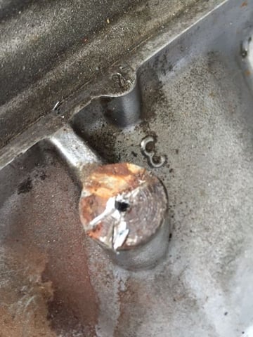
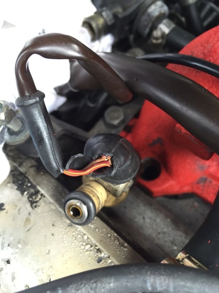
2. The injector wiring is noticeably brittle and i have some deep concerns about the wiring. I'm planning on replacing the last 4 inches of wire and the injector connector on each in the near future, but i have doubts about whether this could be the cause of it not starting?
The worst one i have taken a photo of below. It has copper wire showing through the cracked insulation.
I applied some superglue to the area to act as a temporary insulation to keep the wires separated.
Some of the other injector wires have intact (yet crumbly) connector boots, but seem to have the same problem hidden under those boots, i.e the wire has a weak point that flexes a little TOO easily inside the boot. I suspect bad wire insulation.
Could a short-circuit in the injector wires be causing issues with the start, or have blow a fuse somewhere? I would have thought that as long as the majority of them fired, i'd get a start.
4. I had the battery out of the car for about 4 weeks on a trickle charger while working on it
5. The backfire (when i didn't have the manifold buttoned down) sounded like it came from the engine bay
6. The wiring harness (male plug) from the Throttle Position Sensor was toast. I rewired to the harness using a Deutsch 3 pin connector. I copied the polarity from the female on the short TPS cable, to the female on the harness connector. If i got the polarity wrong, could that create a no-start condition?
Once i had completed the work described above, and tightened everything up, i tried to start it up. On the third attempt it fired up for about 3-4 seconds (sounded very smooth), and then promptly died.
I tried about a half dozen times after that with no effect other than turning the engine under starter power. Doesn't sound even close to starting. Battery volts are fine.
I pulled one of the sparkplug connectors and noted i was getting spark when i turned the engine over.
After working on it for 8 hours straight, i was a bit over it and frustrated, and put the cover back on and called it quits for the day.
Although I'm going to start trouble shooting electrical stuff this weekend, i was wondering if anyone had an A-HA moment while reading the above?
I'm especially suspicious of the backfire, broken injector-wire insulation. and having the battery out of the car for an extended period.
After doing a bit of reading, it seems that the temp II sensor is a common culprit when it's not starting.
I remember pulling those connectors off, seeing a bit of corrosion but not thinking much of it, just pushing the connectors back and forth to cut a contact through the grime.
Will try clean them properly tonight and see what happens.
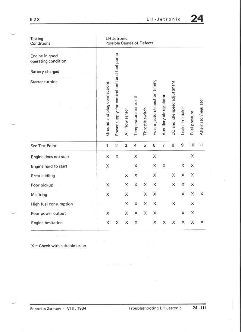
PS - Here's a handy troubleshooting guide for LH ignition not starting.
Just some thoughts triggered by pics. Looks like somebody performed an epic tittytwister on that one injector plug.
I'd begin with a noid light at one of the injector plugs that you can access, like #8. If no light strobe, then several things can cause it. One is a short at any injector plug, and the one pictured, if indicative, looks bad.
Remove brain plugs and perform a continuity check across the leads at that injector. You want to see an open circuit.
If those injector wires short within harness at any plug then none of the injectors fire. They batch fire normally.
If no pulse, another cause is bad fuel injector relay. it can be jumped 30 to 87 at ce panel for a quick check. But sometimes the issue is not the relay itself, but no control voltage to trigger it.
There is a test plan for methodically working thru it within the set of docs from which you pulled the troubleshooting grid pictured.
Am surprised about you grinding the mountings. Typically on these porsches, when something doesn't fit, especially with stock parts, there is a mistake being made.
Same regarding the TB mountings. I've replaced two sets of them on 85/6 cars with correct ones from Roger and IIRC didn't even need to lookup the part number, he knew exactly which ones.
Left handed drill bits are for me a higher percentage/lower risk approach to broken bolt removal. than easy outs. I've actually eliminated those easy outs from my tool set.
I think you're right Landseer, i'm almost certain it was something that i had done that wasn't allowing the injectors to seat properly, eeerm like maybe not cleaning out the injector ports well enough (i later found some gunk at the bottom, where the pintle would rest against the intake socket).
All good in hindsight....i'm sure once i'm finished this car from top to bottom i'll never make these mistakes again
Thanks for the info on the injector short circuit. If it takes them all out, I'm fairly confident that is what is happening. I ordered some connectors and boots yesterday and will hopefully have them in hand before the weekend and get busy with my soldering iron.
I'm also trying to track down a noid light set to test as per your suggestion.
Sorry but I was laughing at a few of your pics, I think our cars were put together by the same person, mine was just as dirty if not worse from the nose to in frt. of rear wheels I used 2 gallons of purple degreaser. Also the throttle body mount you snapped was the same one I did, and also after assembly it wouldn't start but mine had no spark. On the injectors I tried cleaning them and saw two screens were broken, found a set of the new style Bosch for 300 that was after I bought all new seal kits. Could you do me a favor and tell me off the throttle body the side closest to the firewall which port is for the main vacuum splitter and which goes to the thermoswitch, one is larger dia. then the other
Hi Homan,
It's a lot of fun cleaning those valleys out.....it's like a time capsule. I think i found Roseanne Barr's career in there.
From memory, the firewall side of the throttle body has two small vacuum connectors, one that goes to the 7 way splitter, and the other goes to the heater valve connector on the back left corner. I havent got any great photos of them sorry so only what i can remember.
Actually, found the vacuum diagram (assuming you have the '85-86) to confirm:
One consideration is that your current method will likely pass more engine vibration through your single bolts into the air guide and by association into the MAF.
The OE system specifically avoided having one solid metal vibration path going from the engine block into the air guide and then MAF. By using one solid metal shaft instead of to separate shafts separated by a vibration damper, you have created a solid metal path for transmitting vibration to the air guide. There is some chance that you MAF's performance could be affected.
Is this likely to have any noticeable impact in real world use? I have no idea. I have no idea how sensitive the 928 MAF is to vibration, or how prone it is to failure.
+1 to this, including the "who knows?" (probably Gunter and Carl somewhere in the old country) But why de-engineer it and take a chance?
If the new standoffs fail in your lifetime, you won't have a problem removing them again because they'll have been reinstalled after a generous application of Nevr-Seez to the male and female parts, right?

 11-12-2014, 11:43 AM