When you click on links to various merchants on this site and make a purchase, this can result in this site earning a commission. Affiliate programs and affiliations include, but are not limited to, the eBay Partner Network.
I've been working on the Link G4+ Thunder ECU settings for a while [too long], mostly because it's a steep learning curve for me.
A few small wiring errors on my part added to some misinformation in what I needed to do, have slowed down the process.
My current small problem is the crank angle sensor wiring. I'm using the stock crank sensor with 3 pins, which I 'think' are negative [ground in ECU], signal [centre pin] and shielded ground.
I would dearly like an absolute description of of each pins function.
By far my most frustrating task, is getting both of the E-throttles to work correctly.
The accel pedal position sensor works and calibrates just fine but the E-throttle calibration has only resulted in #1 throttle working as it should and #2 passing but it doesn't actually work. At one stage #1 was working beautifully and #2 was working in the opposite direction, while #1 was opening, #2 was closing. NO, it is not wired backwards. I proved this by unplugging the looms at the ECU, bridging both throttles (+) and (-) wires then connecting the bridge to my E-throttle test box and rotating the pot, they both open and shut perfectly.
My last effort was calibrating both E-throttles manually, by moving the TP to closed and open and recording the TP Main and TP Sub voltages then in setup mode, typing the read voltages into the ECU table but that hasn't worked yet either!
Thanks Fred, I'm going to have a play with my oscilloscope. Link guy tells me my signal is wired backwards and I don't have the shield wire connected, [because I followed someone else's diag!], so I'll connect that up as well.
Thanks Fred, I'm going to have a play with my oscilloscope. Link guy tells me my signal is wired backwards and I don't have the shield wire connected, [because I followed someone else's diag!], so I'll connect that up as well.
Sure hope o Fred,
That's the PCLink software for the ECU. I don't have a dash yet, so that's my guide to what's going to 'blow'.
It's ready to start but the ECU is blocking me until I get the CPS and the E-throttles sorted.
It has fired a couple of times before the ECU shuts off the fuel pumps.
Sure hope o Fred,
That's the PCLink software for the ECU. I don't have a dash yet, so that's my guide to what's going to 'blow'.
It's ready to start but the ECU is blocking me until I get the CPS and the E-throttles sorted.
It has fired a couple of times before the ECU shuts off the fuel pumps.
Are you going to have one of those custom dash panels made that use a VDU that sort of looks like the original dash but is completely digital?
Are you going to have one of those custom dash panels made that use a VDU that sort of looks like the original dash but is completely digital?
I'll be using an AIM Motorsport 10" display, which is programmable with RaceStudio3. I hope to be able to get something like the pic attached.
It is connected to a PDM08 in the back of the car and a PDM32 in the front and to the Link ECU via CANBUS, so any data that Link has can be displayed on one or more screens. Link also is connected to the 4 wheel speed sensors [for traction control] so road speed comes from there as well.
It comes very close to fitting into the stock binnacle but I will have do some 'cut and shut' but hopefully I can keep it looking fairly stock.
Some progress. Sorted the crank sensor, Porsche in their wisdom used a 100 tooth trigger wheel on the '86 5.0L engines and my Link Thunder ECU has a 60 tooth limit. Getting the flywheel out in the car looked 'uncomfortable', plus I understand it's not a straight bolt on to fit an S4 flywheel.
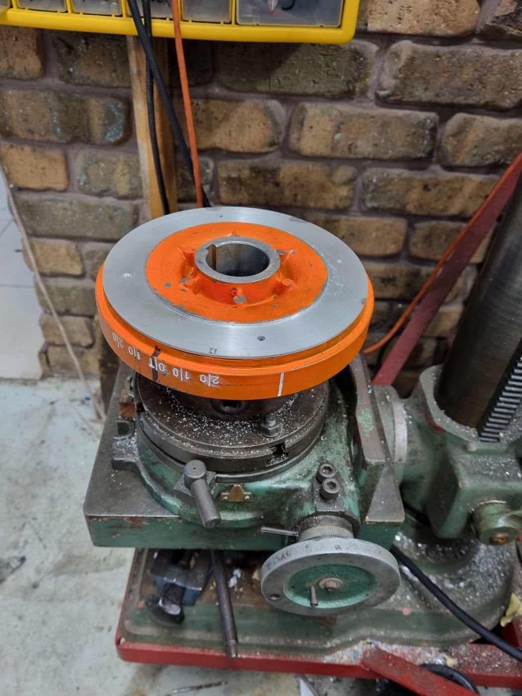
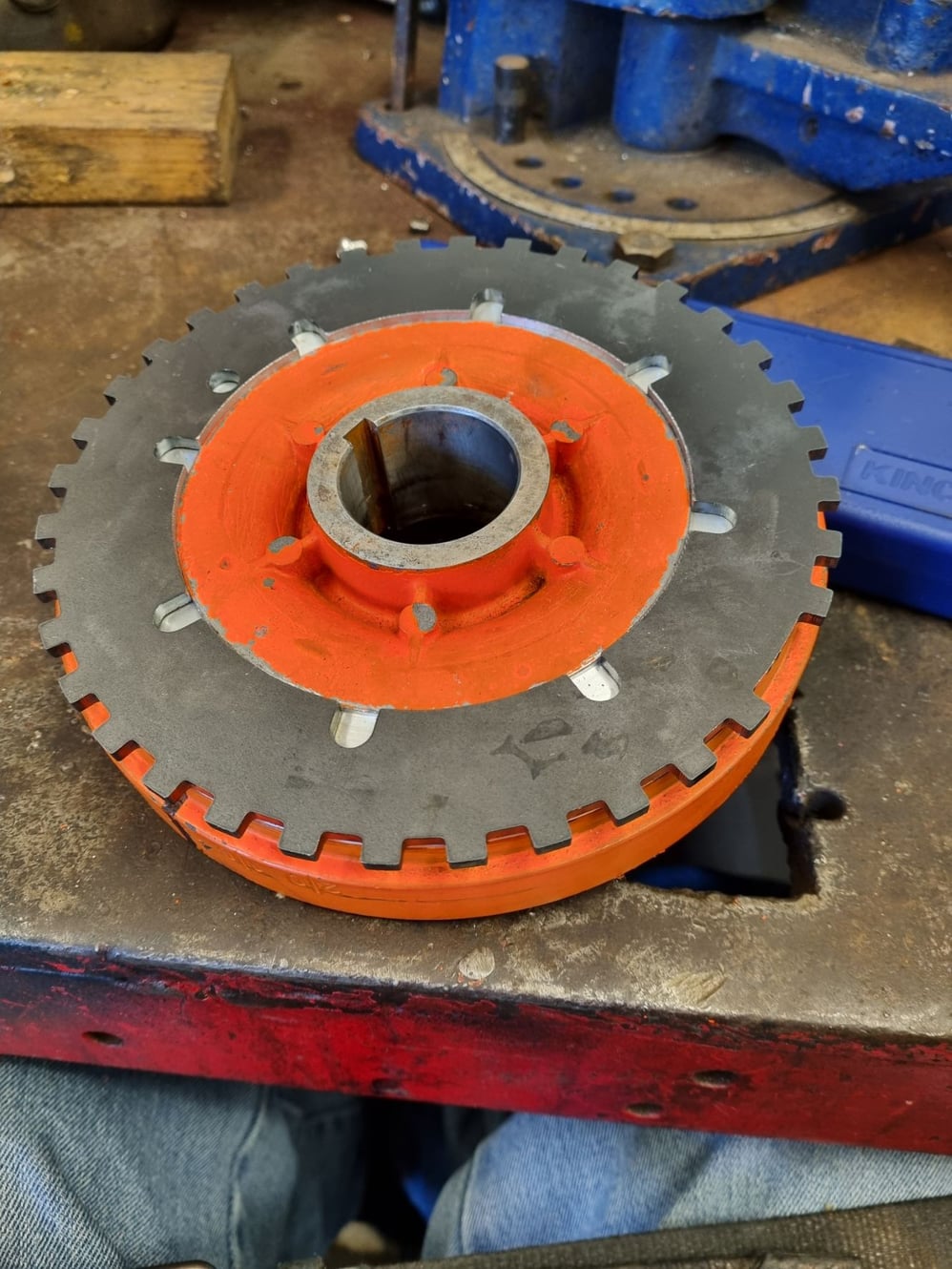
I've gone to a front mounted 36-1 trigger wheel, which is mounted onto the front of the harmonic balancer. The front face is one piece with the central mounting hub, so it is not affecting the 'balancer bit. The balancer has a small lip, so it got setup in my lathe and the face plus the lip got trued up so I'm able to shrink the trigger wheel on and hold it with 4 screws and it 'just' clears the AC belt. Mounted a new crank angle sensor on the 1-4 cyl side where there's a bit of room and it seems to be working fine.
The E-throttles still have me perplexed. I had to change the pedal sensor I had already setup nicely, as it was not compatible. Now the rh bank throttle is working fine but not so the lh bank one, just doesn't move. I can power it with an external pot and it works fine?
Never-the-less, it starts and runs, thanks to the huge crossover between the rh and lh plenums. I just see slightly different Lambda numbers between the r and l O2 sensors. setup for indexing mounting screws shrunk on and locked trial fit on engine custom pulley and trigger wheel 36-1 trigger wheel
Who can tell me a nice safe ignition curve for my 6.5L stroker, with 10.5:1 compression, for street use?
Also, what sort of current draw should I expect from my 044 + the intank fuel pump at 40PSI?
It's running ok in the workshop now, with both E-throttles working properly and now that my new timing light has arrived, the base timing is correct. https://drive.google.com/file/d/1BAC...usp=drive_link https://drive.google.com/file/d/1xyh...ew?usp=sharing
I reckon if you work on the basis of 15 amps for both pumps you should be ok . When I looked into this I found various numbers for the 044 in the range of 11 to 13 amps.
The in-tank pump is the real mystery in that no matter how I tried I could not find a single data point for those things. Obviously it has to flow the same as the 044. The differential head will (I suspect) be no more than about 5ft so should draw less than 1 amp.even if the efficiency is very poor.
Owners have used the in-tank pump with the 044 so logic says it should be ok but my concern was whether it could keep up with it. It would be interesting to see some test data to ensure the thing can develop sufficient head at the 044 flow rates. Whether Porsche ever mated these two pumps together I have no clue.
I would not suggest running the in-tank pump with the 044. It is not needed, and will likely be an impediment to the 044, especially as the internals and hose quickly fail in modern fuel. I would use either the stock strainer or an aftermarket version.
Is the pump you are running the new versions with rubber isolator or the original version?
The new version (0 580 646 200) of the pump should draw around 11A at 3bar with normal 928 system voltage.
The original version (0 580 254 044) should pull around 12.5A at 3bar with normal 928 system voltage.
Note that the original part is only rated for 500hours duty with e85. The newer pumps internals have been updated for better modern fuel compatibility.
There are also several other pumps that are good fits in the factory cradle with modern internals.
Thanks guys.
The pump is 044 number genuine Bosch and I find it noisy for a new pump. The 2 certainly don't have difficulty with flow and pressure, as we have given them quite a work out during setup.
The photo is what happened after about 1/2 hour of running, mostly around 1000rpm, occasionally at 3000rpm, mostly about 3bar but the ECU varies the pressure a bit.
Admittedly the solid state relay was just lying on the floor with no heat sink because this will be controlled by a PDM when it's fitted.
I didn't trust the reading I was getting from my amp clamp, seemed low? so I put the feed to the relay through a spare ammeter from my '28 model A Ford and it sits constantly on 15 amps for both pumps.
The car is about ready to be tuned properly, it starts easily and runs steadily but it's quite 'lumpy' and the 2 AFR readings, especially the right bank, are all over the place and for some reason my rh exhaust gas temp sensor is not showing anything.
Just have to get the Accelerator pedal mounted in instead of just lying on the floor connected to its loom.
The Cayenne coils seem to be lighting the fires ok at 0.9mm gap.

 11-29-2023, 12:28 AM