When you click on links to various merchants on this site and make a purchase, this can result in this site earning a commission. Affiliate programs and affiliations include, but are not limited to, the eBay Partner Network.
This may be the most difficult part of this job. I am sure there is a really easy way to do this. The problem is I can't find a US supplier for this, and I can't bring myself to pay for a new one from Kroon's in Europe. Hard for me to believe I can't find one in the US but oh well....
So - I toyed with the idea of getting a new oval-shaped firewall grommet and just feeding the new harness through with out the extra ribbing and support of the factory snorkel. Could not find a grommet with the correct hole dimensions to match. Thought about buying a used engine harness with the snorkel that I could pull (and cut the harness into pieces to get it off). But that seemed like a waste of $$ and destroying a harness.
So I decided to try to remove the one I have. Here's a video and some pics.
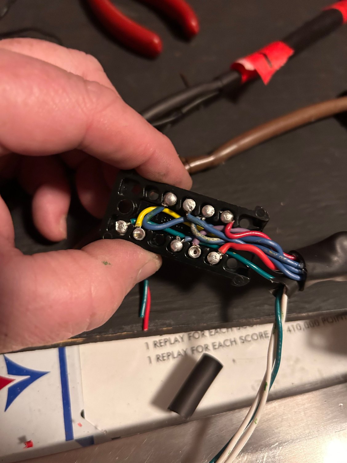
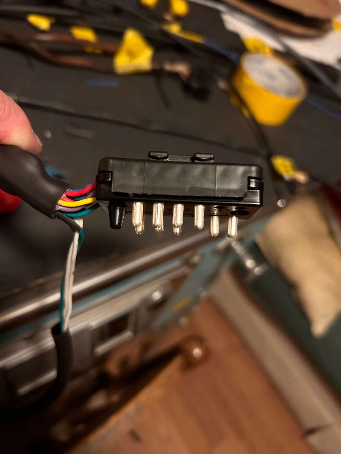
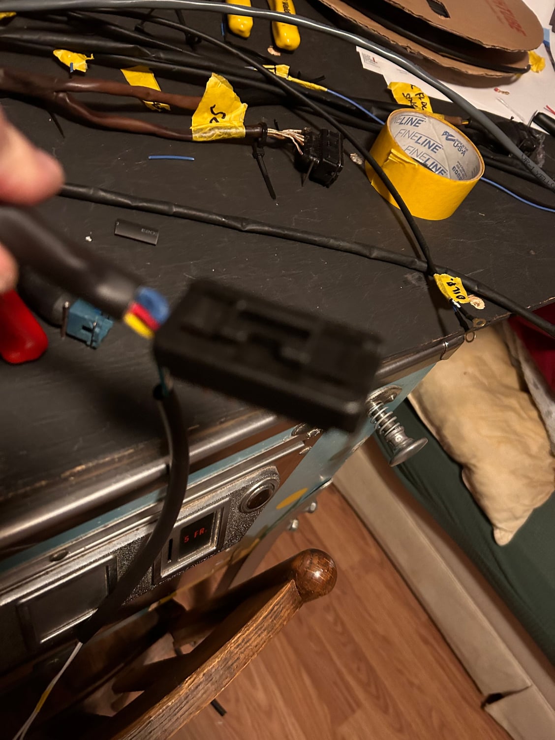
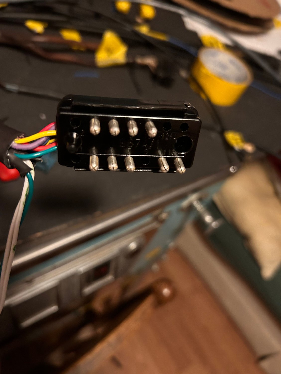
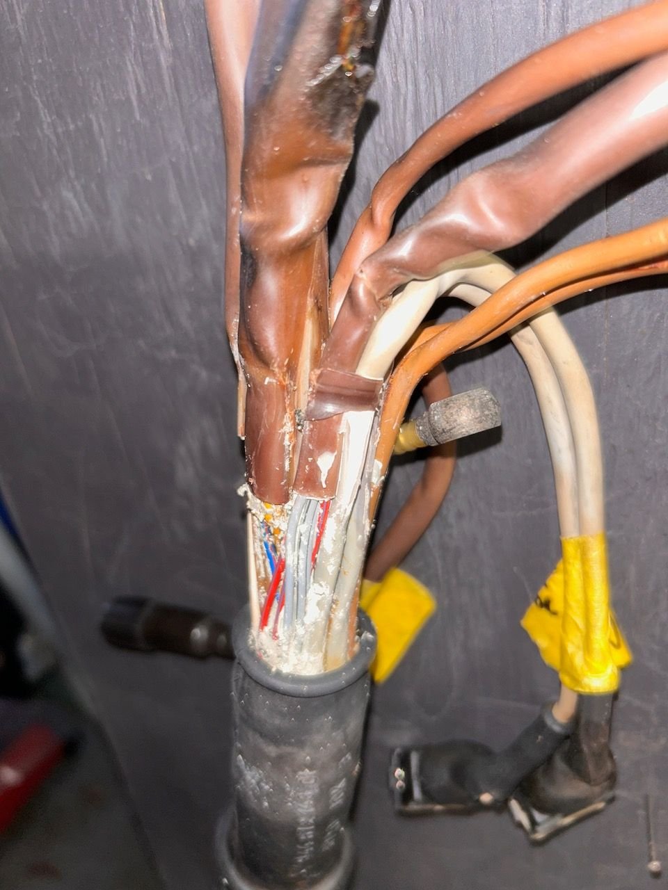
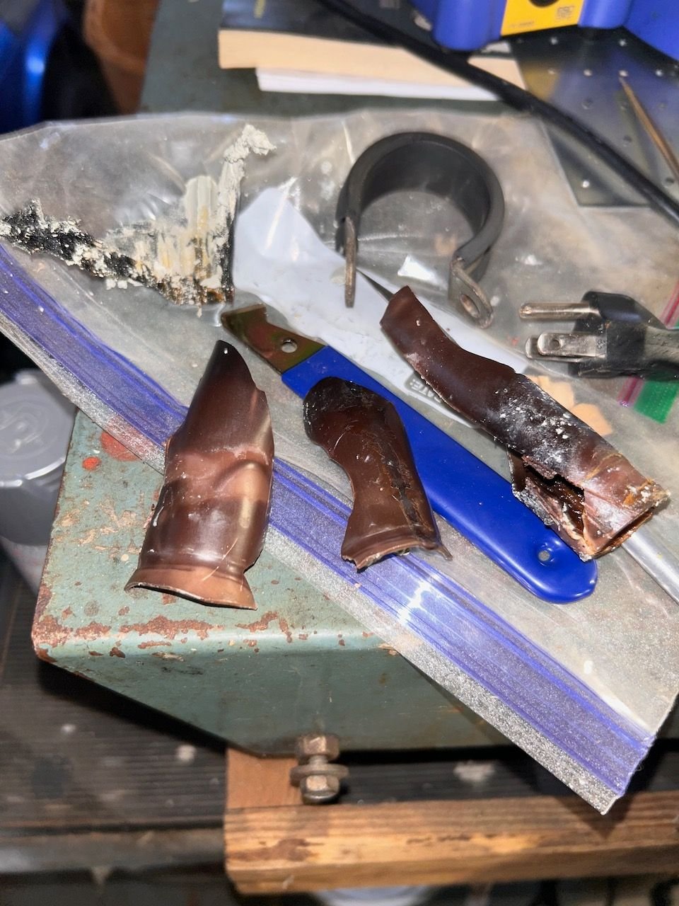
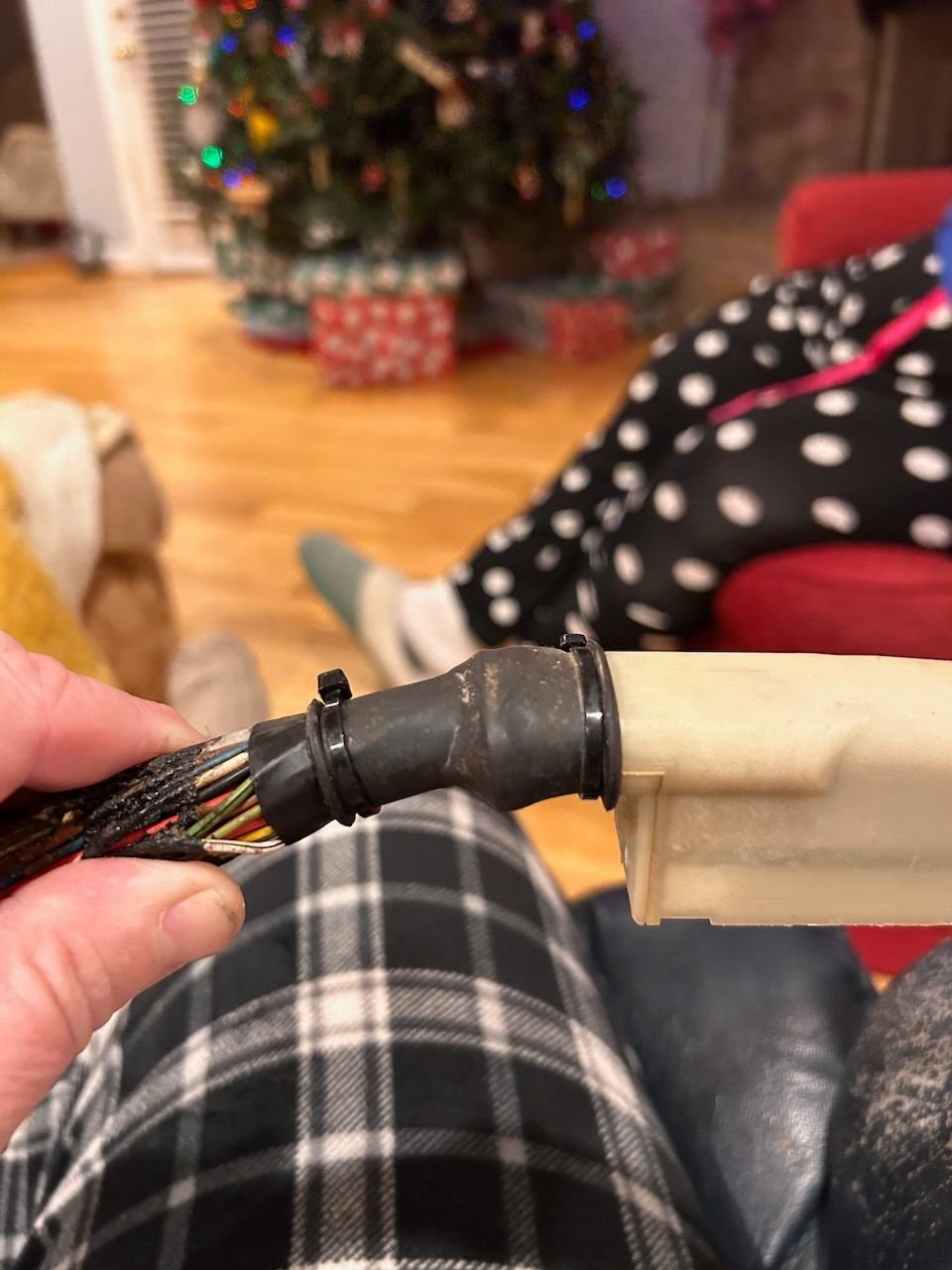
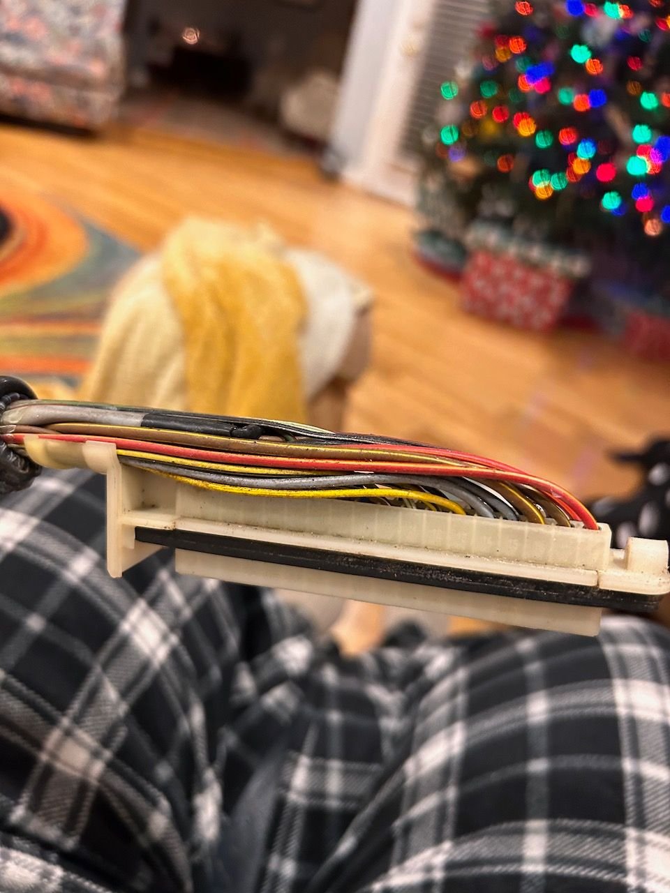
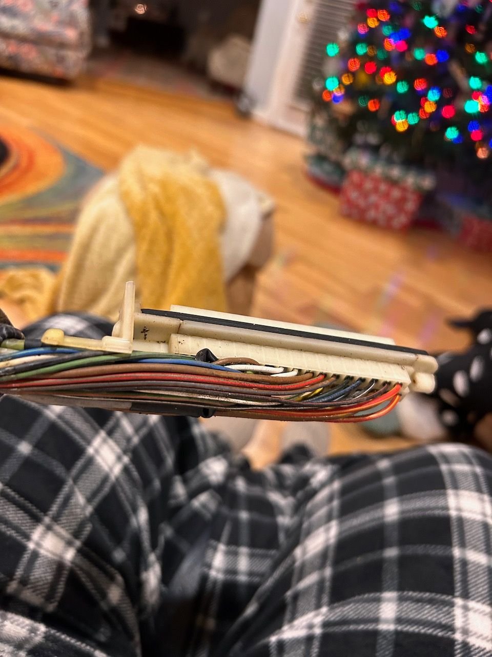
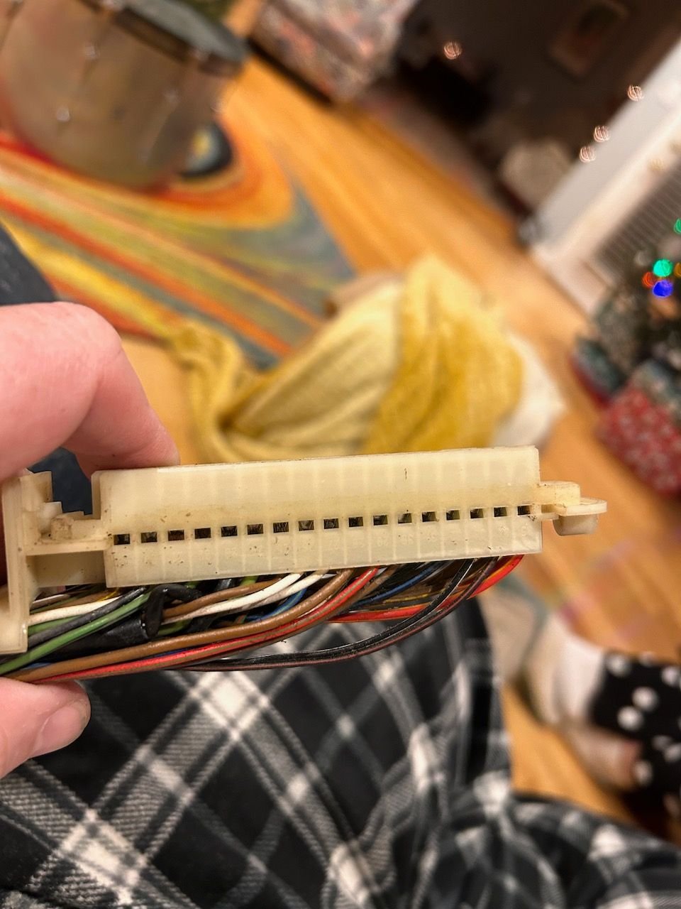
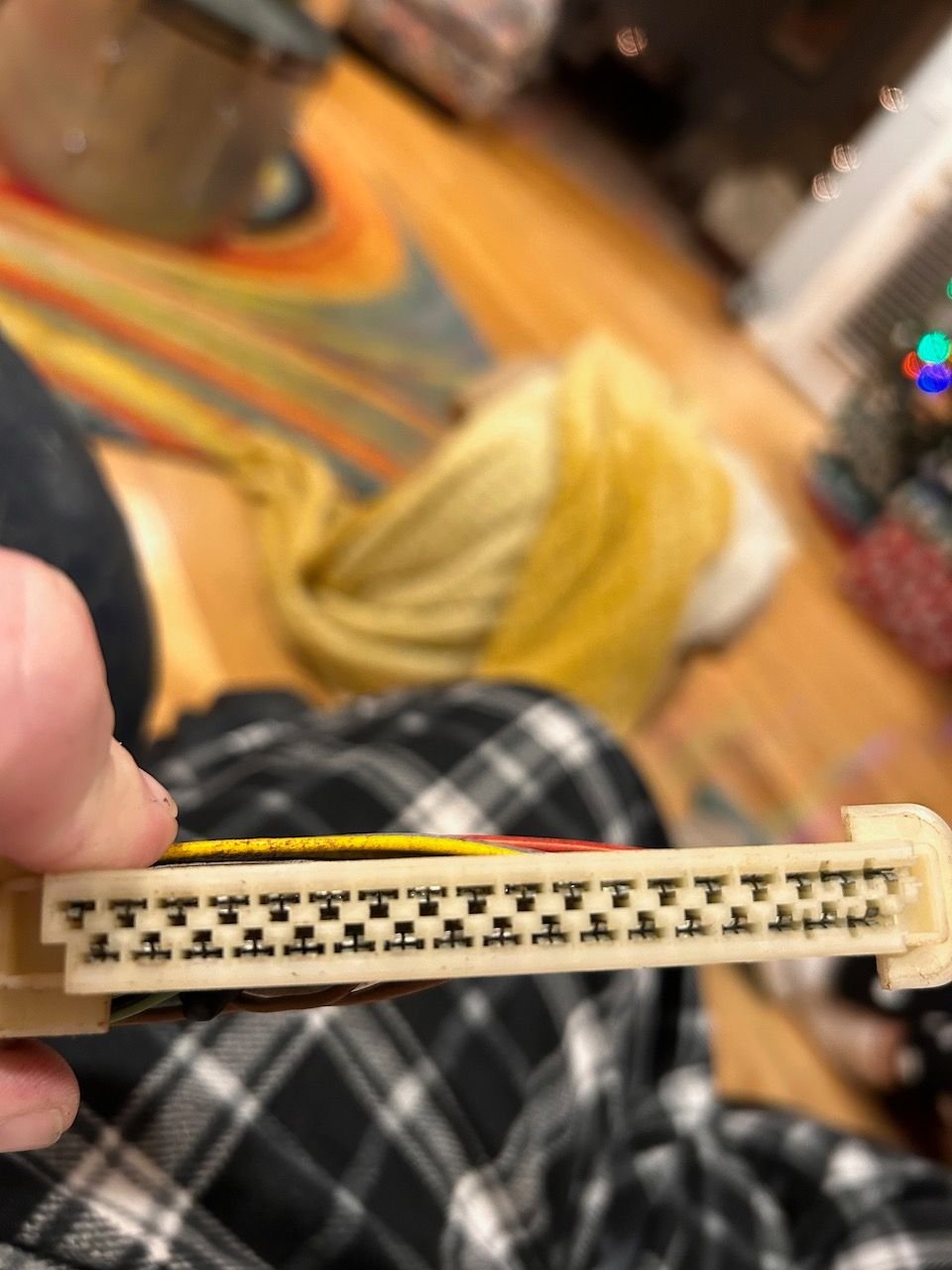
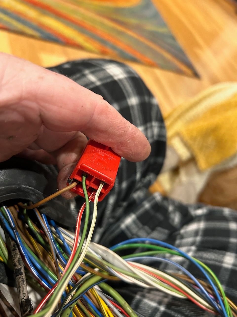
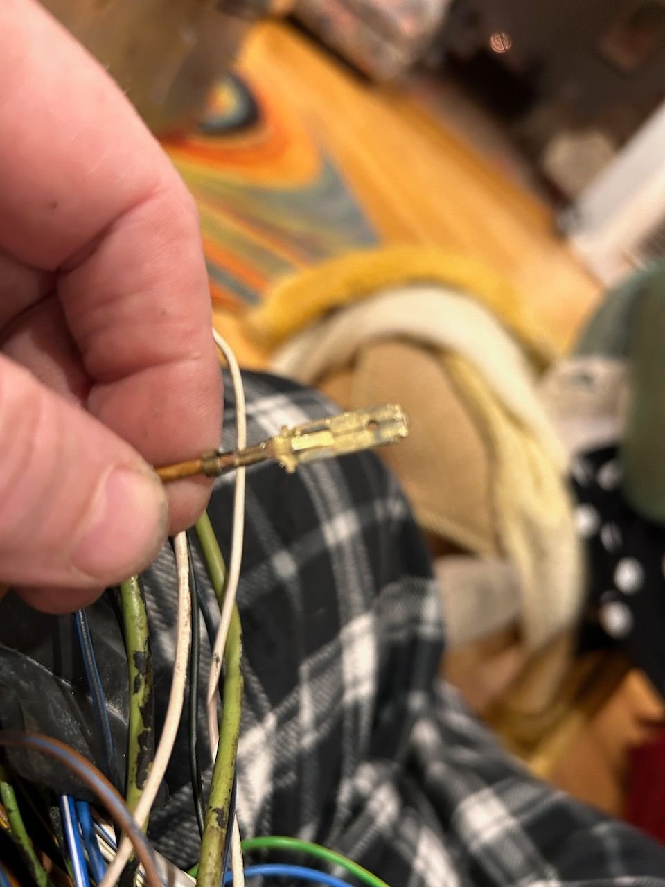
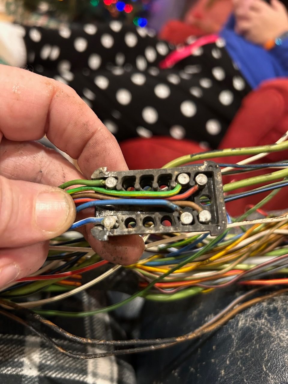
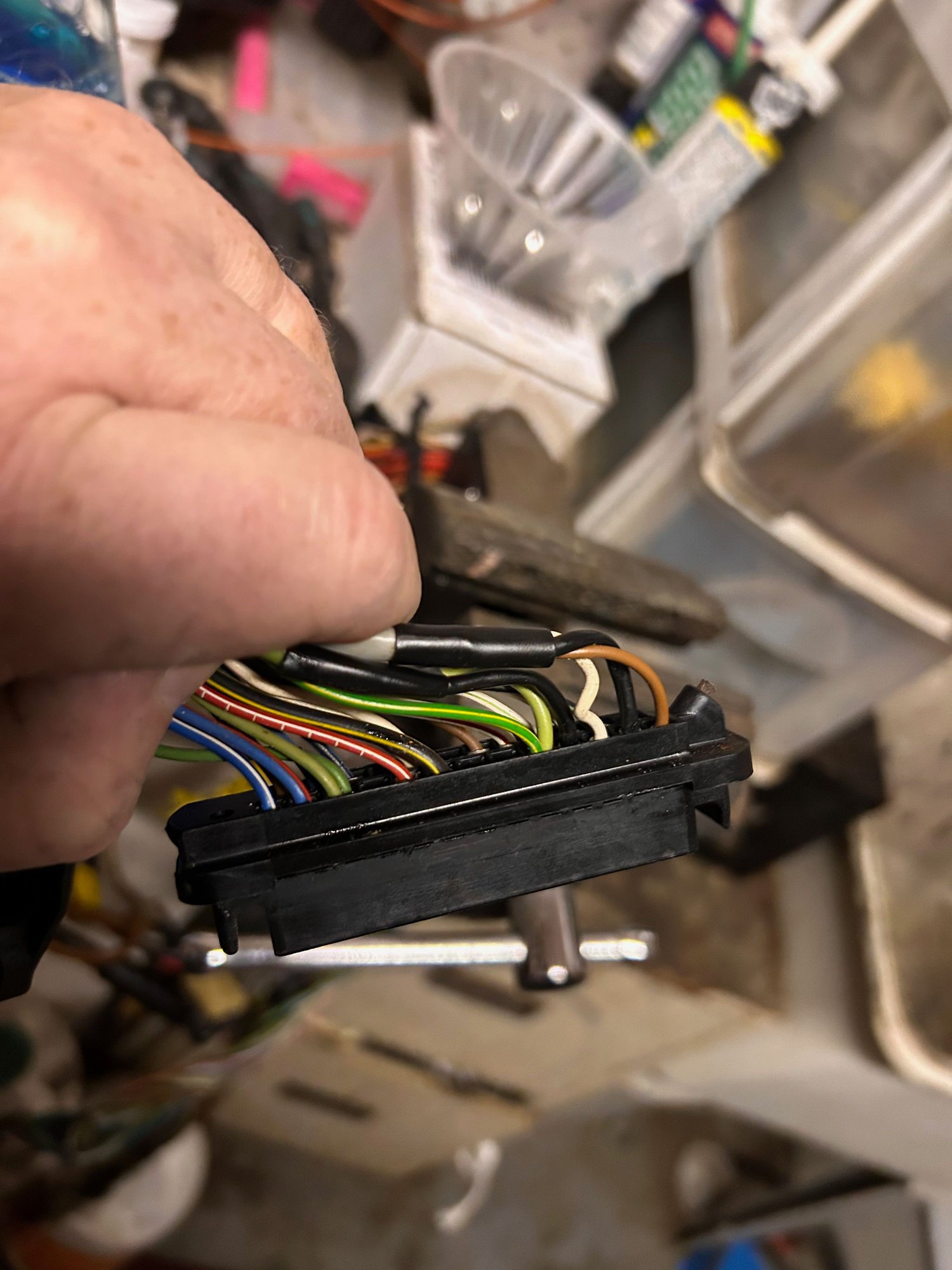
After removing that piece of wrap. There is a good bit of sticky goo underneath as well as some other cloth type sheathing. The wrap was so brittle it broke into several pieces but that's ok. I plan to re-wrap the old harness with a piece of new shrink to keep it all together. Determined that I was not going to be able to pull the wire through from the engine side - so now to figure out these ECU connectors. The 'boot' is held in place with two tie traps. There is one screw on the other end that has to be removed. After removal the cover slides off the plug away from the harness. Here is what it looks like inside. There are two plastic locking tabs that fit into these holes that lock the contacts into the plug. Each wire also has its own individual locking tab. The individual locking tab is the small rectangle above/below the pin slot. I used a jewelers screwdriver to depress the tab and the wire slides out the back. These are the same pins that are used in Bosch Jr Timer connectors (fuel injection, engine sensors, etc.) All the pins out - luckily there is a pinout of the connectors with wire colors. I found it interesting that some of these pins had multiple wires to them. This connector is going to have to come off as well. 4 male blades on this side. There is a locking tab underneath the blade. Once depressed, the blade pulls out the back. Here is the blade from the red connector with the locking tab. Note that the tab is only one one side. This 12-pin connector is going to have to come apart as well as it will not fit through the snorkel. Comes apart just like the 14-pin engine harness connector and the pins slide out. This connector is a service connector and not even part of the new harness.
I even considered slicing the snorkel lengthwise and pulling it off - using zip ties along the route when putting it back together to hold it in place - but who doesn't love a challenge...!
I'd be interested in 3D printing a new snorkel with 95A shore hardness TPU (similar properties to rubber / poly). If anyone wants to ship me a used one I can have a go at modeling it in Solidworks.
You are more than welcome to use this one for scanning. I'll send you a pm.
So I made a quick video of the depinning of the KLR plug - as that had to be done to get through the tube. Figured that might help someone in the future. Few pics to follow with the end result.
Definitely the right approach to remove the snorkel from the DME/KLR side. It should be pretty easy to reassemble those connectors should ever you need to.
If I ever take my harness apart again I'm thinking of ditching the snorkel and going with a more traditional grommet. It's quite a pain getting the snorkel into the firewall with the engine installed. And the length of the tube on the engine side makes some of the wire routing very cumbersome (especially the injector runs). I figure I can affix some sort of plate with a round hole over the existing hole in the firewall and route through that.
I had some trouble getting my new harness back through snorkel, mainly because I used wire with a thicker jacket (GXL). I'm guessing you wont have the same problem, but if you do, try wrapping the wire bundle in something (I used self fusing tape) and then smear it with some silicone grease (e.g.: pic). I figure this could help prevent water intrusion as well.
I'd be interested in 3D printing a new snorkel with 95A shore hardness TPU (similar properties to rubber / poly). If anyone wants to ship me a used one I can have a go at modeling it in Solidworks.
This is a cool idea. Personally, I'd love to have a version that was just a simple grommet, without the tube on the engine side. Since mine is a track car, I'm not that worried about water intrusion.
I assume there are companies that will print this stuff for you if you give them the model?
I think that might be a good idea as far as a couple of varieties of snorkels/firewall grommets. Maybe full size like original, just the actual firewall pass through itself, and I thought about a version where the coily part was about 1/2 as long as it is�
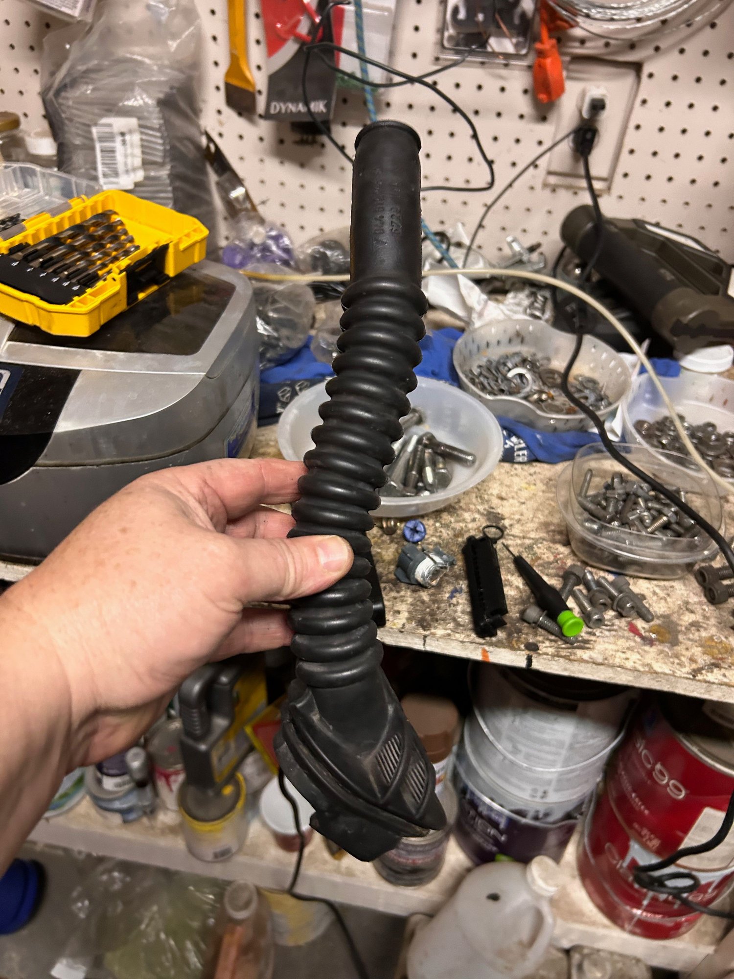
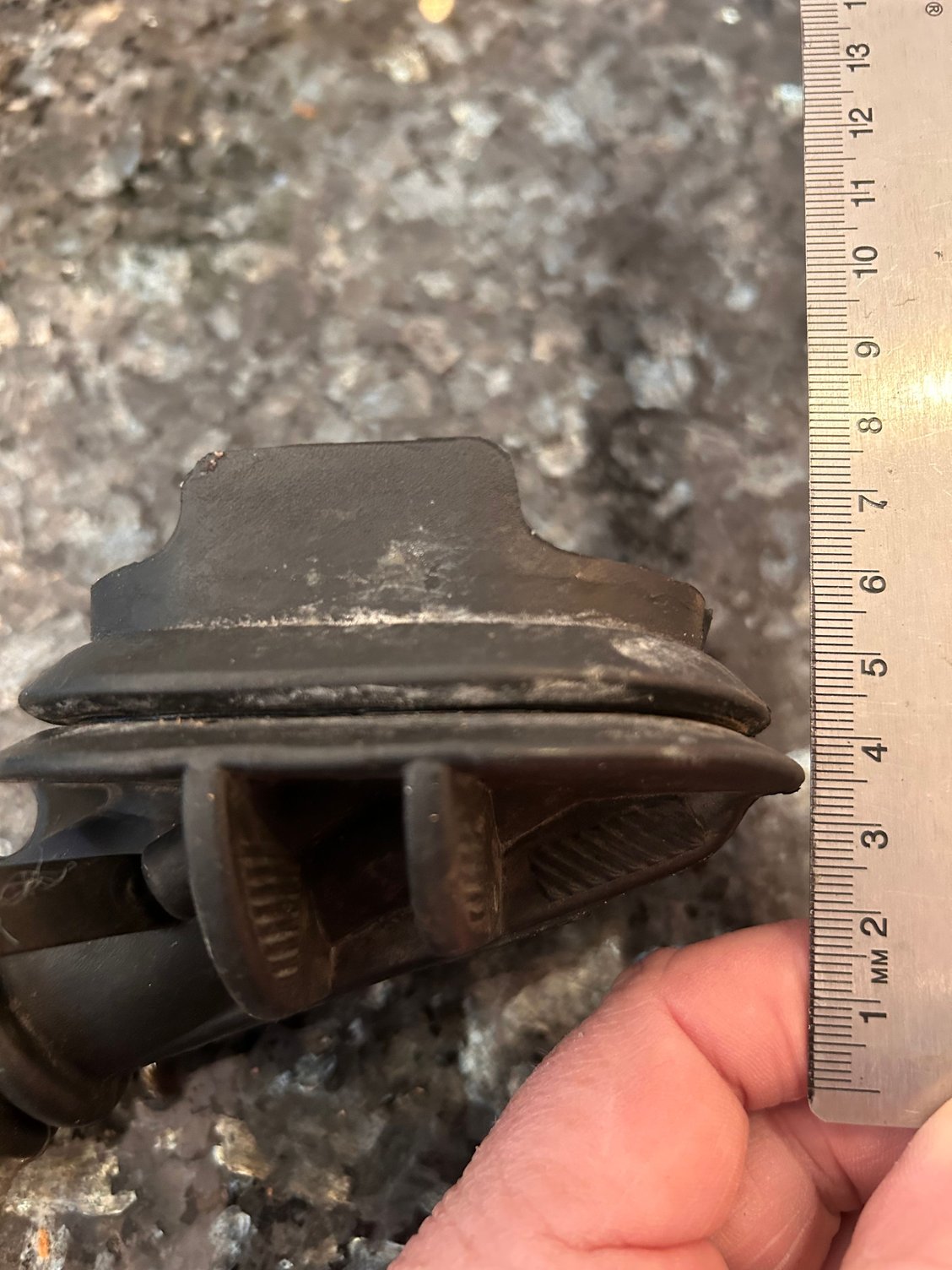
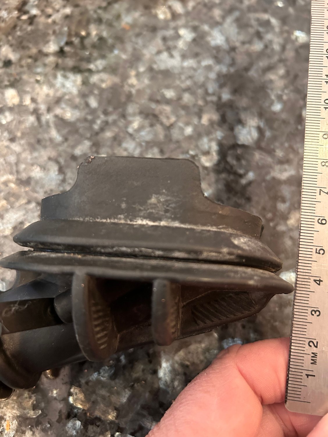
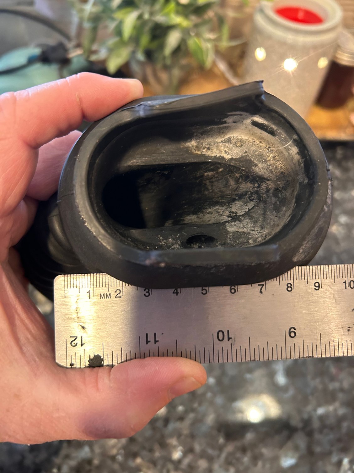
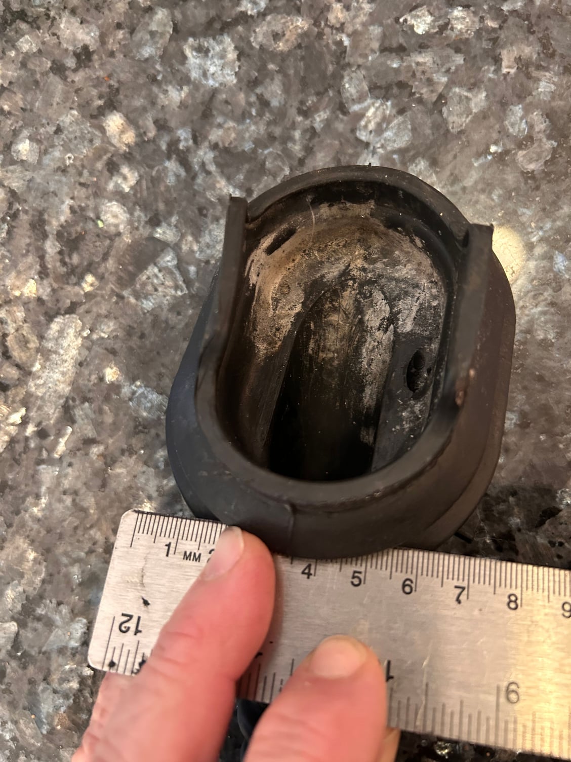
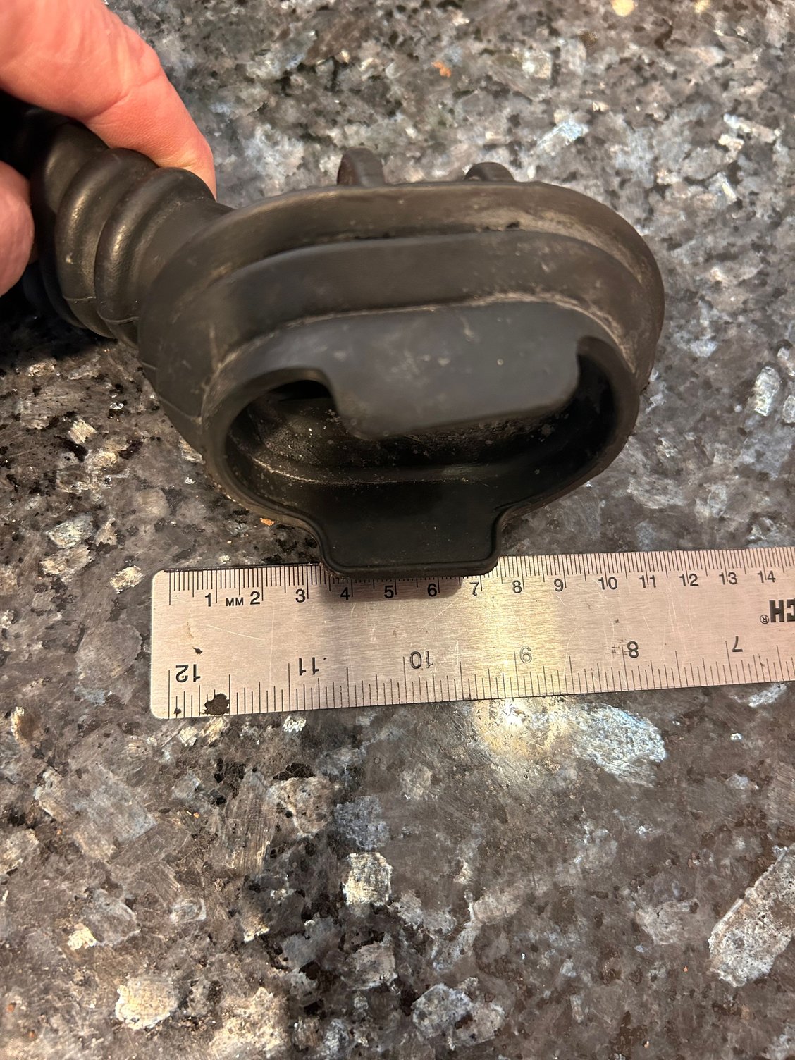
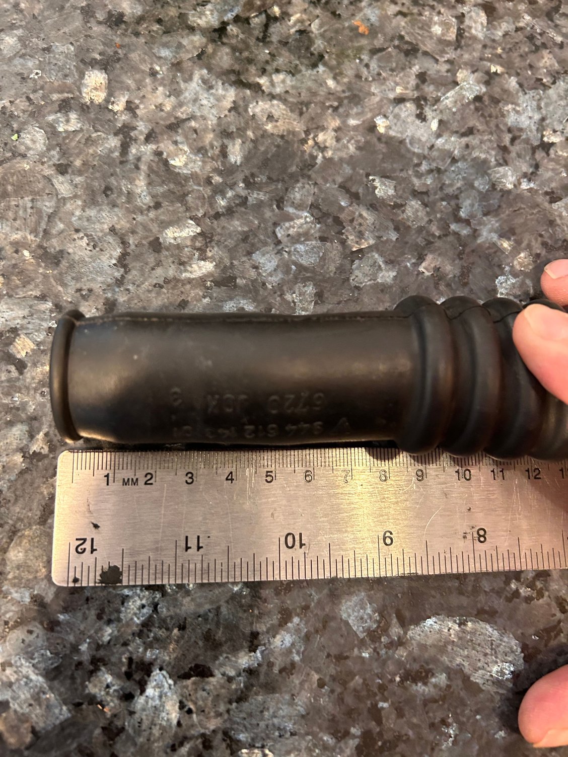
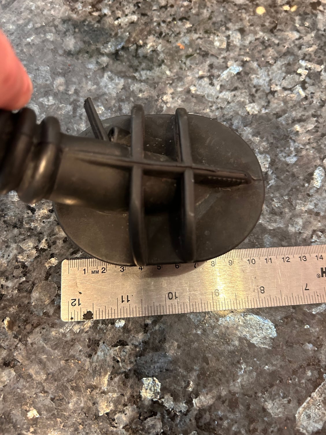
anyways - here are some pics with a ruler for Michael.
Thanks for the photos. I print a lot of TPU in house (literally...) so I reckoned this would an interesting one, no need to outsource anything. However the "snorkel" section of the piece is too long for even my 400x400mm printer to accommodate. So as Dare suggested, maybe a design that's mostly a grommet would be more realistic. It would also be a huge challenge to print a tubular section cleanly with a flexible filament, I don't have a machine capable of utilizing dissolvable supports.
That seems feasible to try. Maybe a grommet piece. Wonder how long of a �snout� your machine would print - even if it was just enough to get the harness pointed north from the firewall towards the head (so not as much pressure on the harness at that point).
A coupe of comments (I didn't read the whole thread so I may be restating something!)
the A/C pin is not a 'trigger' for the A/C, its a signal to the ECU that the A/C has been engaged so it can modify the idle setting. you need an additional 200+/- RPM at idle when the A/C is on. I have been using a 60-2 tooth trigger wheel and hall effect sensor mounted between the alt/AC pulley and the balance shaft pulley for the last 20 years. Laser cut wheel fits inside the stock belt housing and the bracket attaches to the alt/AC belt tensioner. probably made a 100 of them, no problems.
Check out the Dymo label maker using the heat shrink tubing for labeling wires. the 1/4" size will label single wires nicely.
if you want to be extra geeky put a Deutsch 47 pin disconnect in the firewall instead of the stock pass through boot. it looks a lot nicer and makes engine pulling a lot easier.
A few comments and updates and a new video for some feedback�
I think I understand what you mentioned about the AC pin in the 14 pin connector. It should work as you described because microsquirt just needs to see that signal to be able to raise the rpm to compensate.
Ive been looking at my trigger options and have finally come up with something that requires no adjustment of any factory piece. Appreciate everyone taking a look and providing thoughts.
Props on all the DIY efforts. I agree regarding the turnbuckle mounted sensor brackets, not a great solution. I assume you already know, but the Clewett kit is very similar to what you are trying to fabricate: https://www.clewett.com/index.php?ma...products_id=30
I�m using that kit, and yes it�s pricy, but it�s the highest quality and best overall solution for a front mount crank sensor I�ve seen.
Regarding the AC signal. I�m also using that as an input to my Standalone for Idle speed adjustment. Obviously it works great if you already have AC on during startup, or if you turn it on while driving under load. However it is not the best solution for a transient load application at idle speed. When you press the button on the AC control unit in the cabin the compressor turns on, THEN the ECU is made aware that the compressor load is active via the pin in question. So you will experience some momentary idle speed dip until the ECU can adjust. The best method would be to have the ECU handle the control of the compressor clutch activation so that it can preemptively increase ICV duty/advance Ignition slightly before actually activating the clutch to achieve a seamless transition. If I were to do it again I�d find a way to create some cooperative operation between the OE HVAC control unit and the ECU to keep overall functionally of the HVAC unit but give compressor control to the ECU.
Thanks - that is interesting regarding the AC. I thought the signals were simultaneous. That will need some think through. Is the blip so much that it causes a stall at idle?
as far as clewett - yes that is awesome, but I am unfortunately on a pretty tight budget just trying to get the car back on the road.
do you think I will have any trouble with the 6 3/4� wheel like I have mocked up? I think that a wheel is a wheel for what I am doing - and I really don�t want to damage anything from the factory in case someone in the future wanted to go back to stock (eg cutting into the belt covers or wiring harness).


 12-07-2022, 10:06 PM