When you click on links to various merchants on this site and make a purchase, this can result in this site earning a commission. Affiliate programs and affiliations include, but are not limited to, the eBay Partner Network.
I have decided to bite the bullet and convert to MS while I have the engine out of the 86 951. I do not know the condition of the ECU and KLR units as they sit (water leak), do not know condition of old relays, need to rebuild the cooling fan harness, need a new j-boot, plus several other parts. I feel like I can have a better end product as others here have done with MS and replace many of the limiting and 30 year old parts from the original design (e.g. AFM, flywheel sensors, etc.) and also use standard relays and make general improvements.
Here are some other factors:
1. Car is to be a street car (no track use planned).
2. Son will be driving the car, so adjustment of fuel/spark cutout will be nice
3. Cost of brand new parts will be less than parts I need to replace as it was factory
4. Engine is still out of car - wiring will be fairly easy at this point.
5. Plan to use MS to control cooling fans
6. Plan to use factory knock sensor with KnocksenseMS to feed into the MS (no longer need KLR).
7. Using GM LSx coils - already have the 4 coils, bracket, etc. from a 5.3L Yukon
7. 8 foot MS harness will take care of most wiring...will need to rebuild other parts of the original harness for function...
...which brings me to a couple of questions for those who have been down this road:
1. Can someone verify the wiring that will need to remain in the engine bay (for gauge functionality, etc.) that will NOT be feeding from the MS harness?
My research says this:
Engine to 14-pin harness will need to have the following:
Pin 6 oil press ga from pressure sender
Pin 8 Temp Gauge from temp sender
Pin 9 oil warning light from sender
Pin 10 Temp Warning light from sender
Pin 11 Aux waterpump relay trigger from top of turbo
Pin 13 A/C Compressor trigger
2. I have to purchase a new vacuum hose kit (was originally going with Venturi delete). Are there hoses that can be eliminated with the MS setup so I don't buy what I don't need. For instance, I know I will no longer need the vacuum line to the KLR box. I am also thinking there may be some of the larger vacuum hoses in the nest under the intake that I can eliminate.
3. Similar to number 2, I am replacing all of the coolant hoses as I rebuild....is there anything that will be eliminated with the MS system?
TOTAL PARTS ELIMINATED BY THE CONVERSION (SOMEONE CHECK ME ON THIS):
KLR - unknown condition
ECU - unknown condition
Factory O2 Sensor (using a Wideband in MS setup)
AFM - have 2 but unknown condition
Air cleaner box (fed directly from intercooler with integral Intake Air Temp sensor - mine bottom box is broken so would have to be replaced
Distributor/rotor
Coil
DME relay - unknown condition
Cooling fan relay (still need to figure out two-speed fans using resistors) - do not have one so have to purchase
Speed sensor and reference sensor (and the broken bracket I have to replace)
Swap the turbo harness for an S or S2 harness since you won't need the KLR plug
I run a 88 turbo motor swapped into an 86na using a DIY autotune MS box for the S/S2 engine I had to change to an S/S2 flywheel
there are more than enough unused wires to cover a boost control valve but you will have to rewire the turbo water pump
the base map that comes with it will get the car running
you will still need the hose from the KLR for the Map for the MS
Originally Posted by drscottsmith
All -
I have decided to bite the bullet and convert to MS while I have the engine out of the 86 951. I do not know the condition of the ECU and KLR units as they sit (water leak), do not know condition of old relays, need to rebuild the cooling fan harness, need a new j-boot, plus several other parts. I feel like I can have a better end product as others here have done with MS and replace many of the limiting and 30 year old parts from the original design (e.g. AFM, flywheel sensors, etc.) and also use standard relays and make general improvements.
Here are some other factors:
1. Car is to be a street car (no track use planned).
2. Son will be driving the car, so adjustment of fuel/spark cutout will be nice
3. Cost of brand new parts will be less than parts I need to replace as it was factory
4. Engine is still out of car - wiring will be fairly easy at this point.
5. Plan to use MS to control cooling fans
6. Plan to use factory knock sensor with KnocksenseMS to feed into the MS (no longer need KLR).
7. Using GM LSx coils - already have the 4 coils, bracket, etc. from a 5.3L Yukon
7. 8 foot MS harness will take care of most wiring...will need to rebuild other parts of the original harness for function...
...which brings me to a couple of questions for those who have been down this road:
1. Can someone verify the wiring that will need to remain in the engine bay (for gauge functionality, etc.) that will NOT be feeding from the MS harness?
My research says this:
Engine to 14-pin harness will need to have the following:
Pin 6 oil press ga from pressure sender
Pin 8 Temp Gauge from temp sender
Pin 9 oil warning light from sender
Pin 10 Temp Warning light from sender
Pin 11 Aux waterpump relay trigger from top of turbo
Pin 13 A/C Compressor trigger
2. I have to purchase a new vacuum hose kit (was originally going with Venturi delete). Are there hoses that can be eliminated with the MS setup so I don't buy what I don't need. For instance, I know I will no longer need the vacuum line to the KLR box. I am also thinking there may be some of the larger vacuum hoses in the nest under the intake that I can eliminate.
3. Similar to number 2, I am replacing all of the coolant hoses as I rebuild....is there anything that will be eliminated with the MS system? NO
TOTAL PARTS ELIMINATED BY THE CONVERSION (SOMEONE CHECK ME ON THIS):
KLR - unknown condition YES
ECU - unknown condition YES
Factory O2 Sensor (using a Wideband in MS setup) YES
AFM - have 2 but unknown condition YES/NO SEE BELOW
Air cleaner box (fed directly from intercooler with integral Intake Air Temp sensor - mine bottom box is broken so would have to be replaced I STILL HAVE THE ORIGINAL AIRBOX/AFM IN PLACE JUST DRILLED A HOLE IN AFM TO PIN IT WIDE OPEN WELDED A BUNG INTO IC TO THE INTAKE PIPE AND PUT MY IAT SENSOR RIGHT IN FRONT OF THE THROTTLE BODY
Distributor/rotor WILL NEED UNLESS YOU ARE DEVELOPING A WAY TO GET CRANK POSITION SIGNAL
Coil
DME relay - unknown condition NEEDED TO POWER DME/FUEL PUMP N COIL
Cooling fan relay (still need to figure out two-speed fans using resistors) - do not have one so have to purchase NOT PART OF DME/KLR HARNESS
Speed sensor and reference sensor (and the broken bracket I have to replace)
Thank you for the reading and the reply. Here are a few clarifications based on your comments.
I am going to build a sub-harness with single standard relays to power the fuel pump, MS unit, and the cooling fans. The main relay will engage from the old coil power wire from the ignition switch terminal. This really will then power up the other relays. Fuel pump will engage via ground from MS. I think that will eliminate the DME relay and fuel pump relay, and replace them standard relays - also the wiring will be upgraded so another plus. This is why I asked about the engine harness...I am going to only need to run wiring in the 'new' engine harness for anything that does not go through the MS (e.g. gauge senders).
I am going to switch over to a crank mounted toothed wheel setup with a sensor to be able to eliminate the distributor, coil, and speed and reference sensors.
I misspoke about the cooling fan relay in he DME harness - it is actually the sensor for the turbo water temp that I am thinking goes through the due harness to the relay. Then the wiring from the harness is separate to the fans themselves.
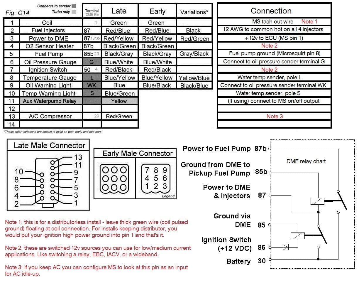
This schematic may help, it details the firewall connector. I just cut it off the old harness and adapt it to the new harness. Did this conversion on my NA around 7 years ago.
I replaced my DME relay with generic relays but if I had to do it again (which I am on my 951) I would leave it in place. The amount of extra wiring detracts from the appeal for me. With a solid state DME relay, I am not really concerned anymore about it randomly failing. You can see in the schematic below how the MS can natively control the relay without anything more than connecting 1 pin.
thanks for replying as well and very interesting as your model of work was what I was going to (at least semi) replicate.
my plan was to get a combo relay/fuse block that would live between the battery and a/c blower. Keep the MS inside u see the dash, and build all new wiring (use the MS 8� harness for everything possible and build a new harness for everything else that plugged back in to the stock 14-pin at the firewall.
I�ll go back and investigate the solid state relay. Maybe I will end up with some type of hybrid setup.
are you still good with the crank-mounted 36 tooth wheel?
I think I have decided to go the "Hybrid" route. I am going to keep the DME relay and Fuel Pump relay and associated setup, but build out a new engine harness with only what I need. I built several new front engine 928 harnesses a few years ago so its not too difficult.
This way, I will have only the needed wiring, it will be all new with new connectors, and take full advantage of the MS system.
Will keep this post going through the process. Anyone got a scrap firewall snorkel they want to get rid of?
Same exact thing I concluded made the most sense for my 951. Curious where you connect the tachometer output wire, on my early NA it was different. I believe there�s a connector under the glovebox it goes into but I haven�t really checked in depth.
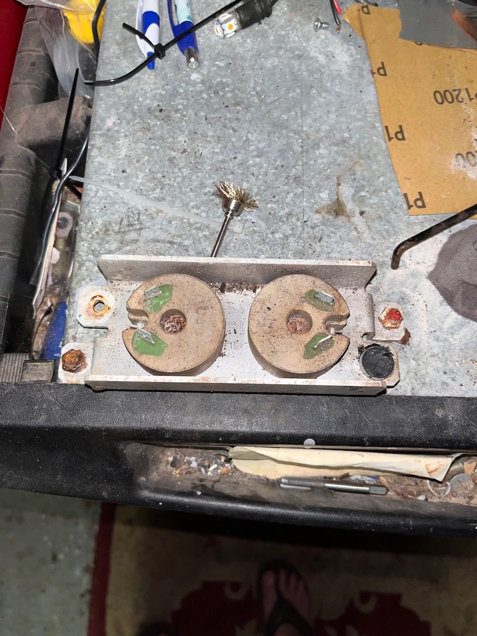
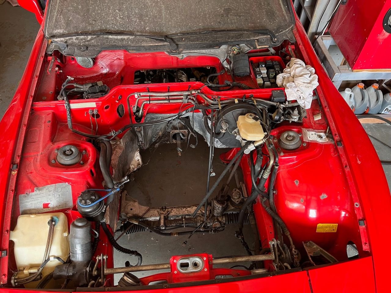
I'll have to look at that - I have not started the install yet. My interior is stripped right now as well as engine out, so I have a pretty clean slate to work from. Interior Broken resistor pack (left resistor is busted). Empty engine bay
Michael did you mess with adding anything via the CAN-Bus? Apparently there is a way to use a fan controller module if it can be controlled via CAN-Bus and an adaptor. I need to replace my cooling fan reisistors anyway (broke one) and the wiring to them is shot. Would love to add this kind of setup instead of just an "on-off" controlled by FIdle output. Any thoughts? If I am thinking about it correctly that would be the only item I would use CAN-Bus for.
I experimented with a CANbus wideband but removed it. For cooling fans, I just used a spare pin on the MS as a programmable on/off output. It toggles a relay at a certain coolant temp value. This relay replaces the fan switch in the radiator, effectively handing over fan control to the MS.
Thanks Chris. I think the on/off will work�was just thinking about how to use a fan controller to get a slower ramp up and low speed with just the MS.
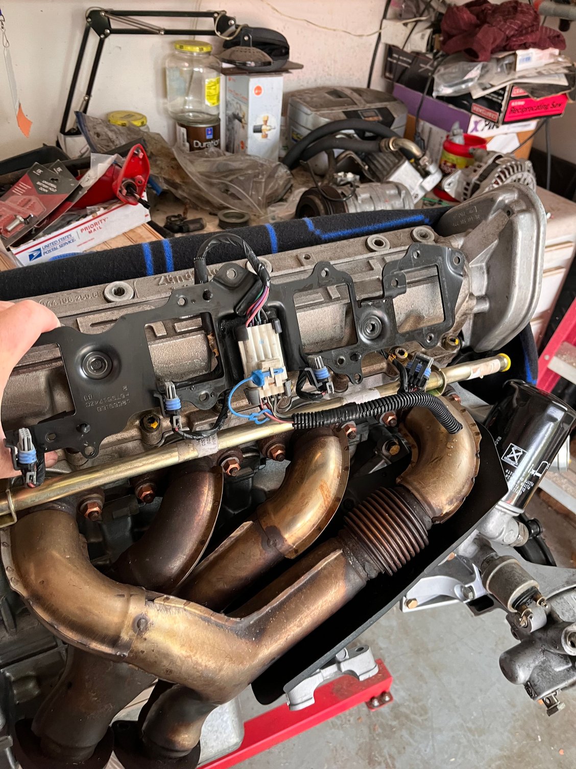
Here are my thoughts for a mounting for the bracket and coil packs. Mount coil bracket on two aluminum stand-off brackets mounted to the cam cover bolts (in the same way the hot water tube mounts). I see the heat factor here being not really different from mounting to the inner fender - both are above the headers.
So far just videos....Decided to vlog the creation of the new wiring harness for the engine bay to support MS and everything else in there. Here is the first of 8 so far on the Fifty-50 Garage Channel.
Please let me know what you think and more importantly, what mistakes I have made!
Updates to project so far:
Planning to use CANBUS and Arduino now for three purposes...
1. Cooling Fan PWM Drive (Using Coolant Temp and Turbo Coolant Temp sensor values from MS inputs)
2. Output to Turbo Dash Gauge to maintain functionality
3. Output to 16x2 LCD Screen (probably mount below radio) to use as AFR gauge + other potential readouts
On the fence about using a stock GM Engine control module from 84-87 Corvette for Knock Sensing module from junkyard, etc. or actual new Knocksense module.

 09-08-2022, 09:56 PM