
The MegaSquirt Thread (pics)
 04-20-2006, 02:58 AM
#241
Instructor

Join Date: Jul 2005
Location: Pasadena, CA
Posts: 227
Likes: 0
Received 0 Likes
on
0 Posts
Wow, that does look cool. How well did it work on the Audi?
Is it going to be able to handle our flywheel trigger, or are you going to add a 60-2 trigger?
It looks like someone was working on getting it to work with the 944 with the 'auditrigger' setup: http://www.vems.hu/wiki/index.php?pa...agnusKarlstrom
Is it going to be able to handle our flywheel trigger, or are you going to add a 60-2 trigger?
It looks like someone was working on getting it to work with the 944 with the 'auditrigger' setup: http://www.vems.hu/wiki/index.php?pa...agnusKarlstrom
 05-08-2006, 11:32 PM
#242
Drifting
Well, tonight AlexE and I got his 944 turbo running with Megasquirt 2/EDIS 4. We had a couple wiring issues to get figured out and one nice backfire. Once everything was in place, it fired right up and idled on its own. With our shot-the-dark style tuning, the base map turned out to be enough to make it idle at 13:1 afr. Once we're able to get the EGT up and running and wideband piped in to MS2 module we'll be off to do some road tuning.
SUCCESS!
Link to Pelican Thread
SUCCESS!
Link to Pelican Thread
Last edited by JustinL; 05-09-2006 at 12:26 AM.
05-09-2006, 12:45 AM
#243
Burning Brakes
Join Date: Aug 2002
Location: Fort Lauderdale, Florida
Posts: 982
Likes: 0
Received 1 Like
on
1 Post
Congradulations!!
I have been tuning my own chips, and let me tell you, it's a pain in the ****. This could be perfect for the 944 community. Please keep us all updated on the details.
My hat goes off to you,
John
I have been tuning my own chips, and let me tell you, it's a pain in the ****. This could be perfect for the 944 community. Please keep us all updated on the details.
My hat goes off to you,
John
05-09-2006, 01:41 AM
#245
Pro

Join Date: Mar 2002
Location: Edmonton, Alberta
Posts: 747
Likes: 0
Received 0 Likes
on
0 Posts
Part I
http://forums.pelicanparts.com/showt...hlight=project
PartII
http://forums.pelicanparts.com/showt...hreadid=278424
PartIII
http://forums.pelicanparts.com/showt...hreadid=280745
PartIV
http://forums.pelicanparts.com/showt...hreadid=281724
Here is the info on the build up.........
Will post the details on the tuning on Pelican.
Big Thanks to JustinL............ he is one sharp cookie.........
05-10-2006, 03:20 AM
#247
Three Wheelin'
Originally Posted by IanS
Wow, that does look cool. How well did it work on the Audi?
Is it going to be able to handle our flywheel trigger, or are you going to add a 60-2 trigger?
It looks like someone was working on getting it to work with the 944 with the 'auditrigger' setup: http://www.vems.hu/wiki/index.php?pa...agnusKarlstrom
Is it going to be able to handle our flywheel trigger, or are you going to add a 60-2 trigger?
It looks like someone was working on getting it to work with the 944 with the 'auditrigger' setup: http://www.vems.hu/wiki/index.php?pa...agnusKarlstrom
On 951, it can utilize stock sensor (you have to specify the sensor type when ordering).
We are probably going to install one on my friends 3.0 8v 951 in a week or so but we are going to use 2 Hall sensors (not the stock ones).
05-11-2006, 02:41 PM
#248
Drifting
Originally Posted by AlexE
Big Thanks to JustinL............ he is one sharp cookie.........
Thanks, and no problem man! Will work for food

I've got my Megasquirt hooked up now too. Right now it's only datalogging, but hopefully once I hook up the last couple wires I'll be able to take it on the road and let it just control fuel.
My passenger footwell is a MESS of wires with the MS, Link AFM, DME and KLR.
Link to My MS2 thread with stock harness
Last edited by JustinL; 05-13-2006 at 02:39 AM.
07-28-2006, 01:06 PM
#249
Addict
Rennlist Member
Rennlist Member
Thread Starter
Time for an update...
I did a test between two variations of the divide by three circuits that I got last night. I tested beab951's (I think I got the forum name right...) and a simple one that uses a cheap little 4017B Decade Divider. For what I need them to do with MegaSquirt, both seem to work identically and equally well, all the way up to 35,000RPM. I went with the 4017 chip, since its circuit is much simpler, it only needs a few wires.
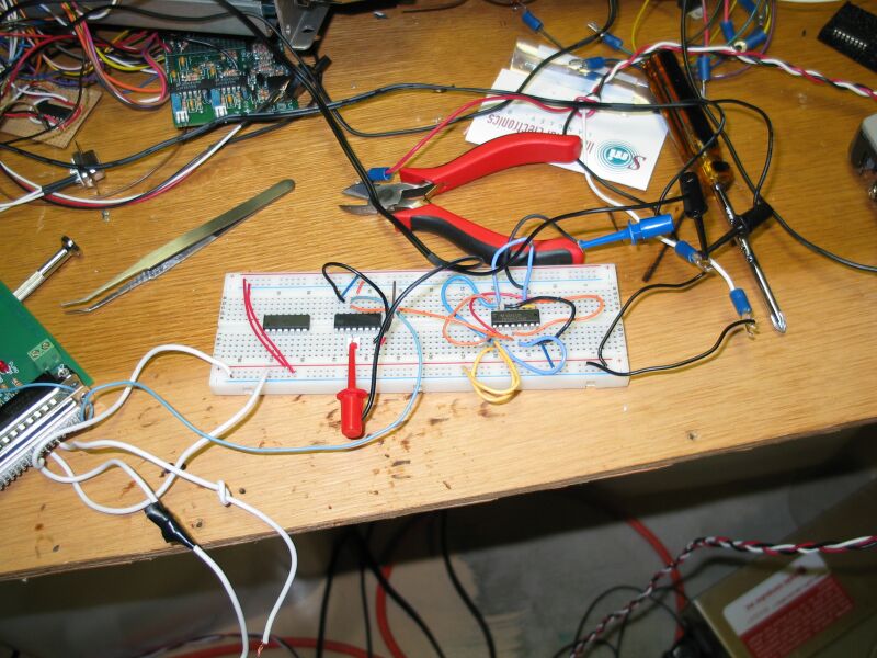
This is the test layout. The chip on the right is the 74HCT109E chip that Beab951 suggested. The middle one is the 4017. The line in between is the output from the MS Stim.
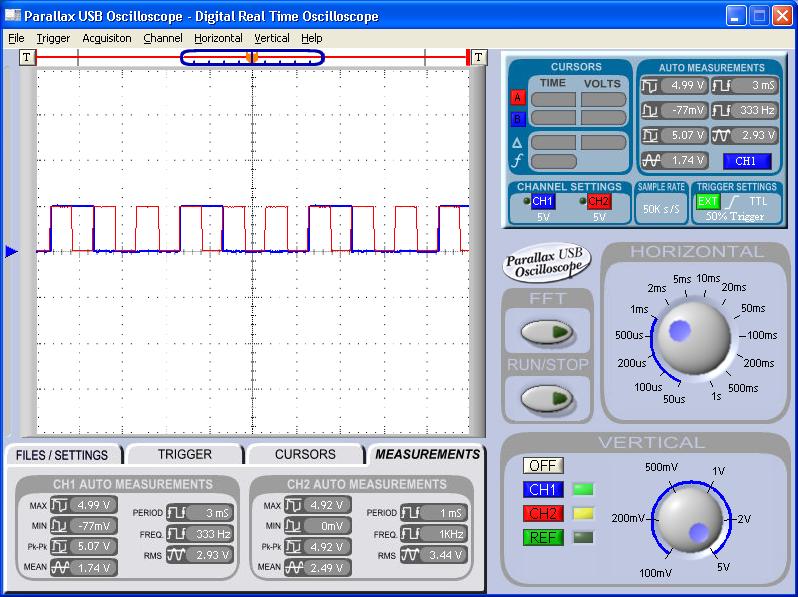
The red signal is the input from the stim. Once the VR signal goes through the LM1815 filter chips, it looks identical to that as well, a 5 volt sqaurewave. The blue is the divided signal.
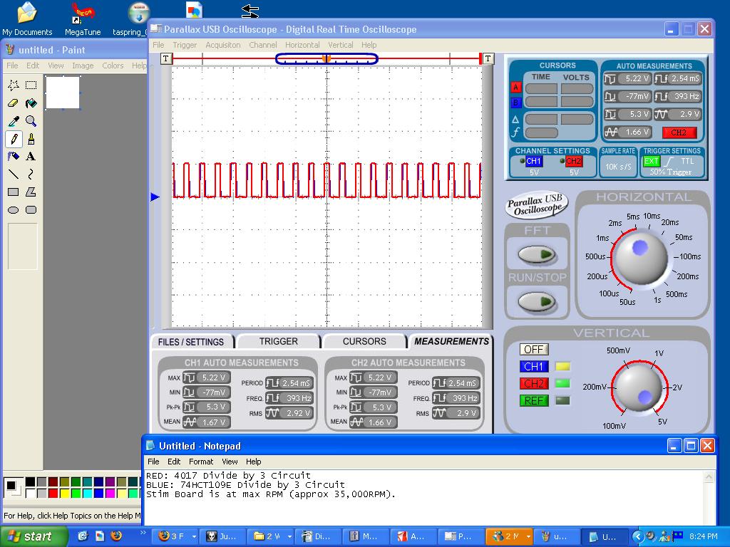
This is the results of the first image. Both are running off the same signal. I did this test to see if one was significantly faster/different than the other, but that doesnt seem to be the case.
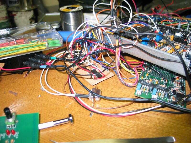
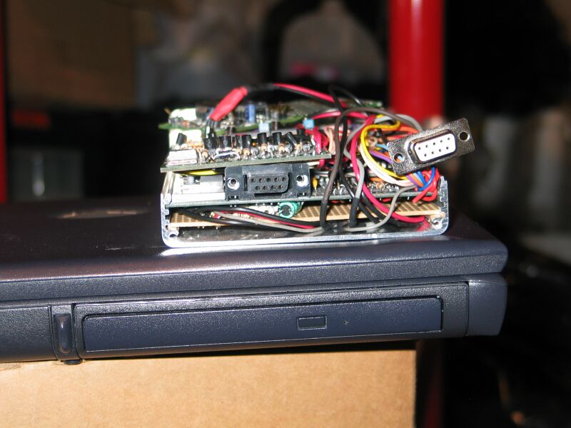
This is a crappy picture but oh well. The green board is the MSNE Daughterboard. The two side by side ICs are the LM1815s for the VR sensors. The output of one of them goes to that brown prototyping board. The circuit closest to the camera on that board is the 4017 divider. That divides the signal, then its output goes to the MS CPU. The ouput of the other LM1815 goes straight to the MS board, since that LM1815 is for the reference sensor that triggers off the TDC stud.
For the curious, on that protoboard is also my barometric correction circuit, and a complex little bugger of a circuit that handles my table switching. Its a push on push off circuit, so that I can use a central locking switch to switch between fuel/spark/boost tables on the MS. When its activated it lights the red light inside the switch... Its the Make-Car-Go-Faster Switch
And the price of the 4017? 35 cents each. But you get a price break at 100, down to 31 cents each!!
http://www.mouser.com/search/Product...ualkey51120000
I will post the circuit diagram when I get home tonight, but I have it memorized. Pins 8, 13, and 15 are grounded. Pin 16 goes to 5 volt (can be 12 or 9 or whatever, but I hooked it to the regulated 5 volts). Pin 10 and 7 are jumpered together (this makes the 4017 count to three then repeat, since pin 7 is the 4th output). Signal in goes to pin 14. Signal out goes to pin 4. And thats all it is.
I havent run the car with it yet, but testing indicates the LM1815 and the divider all should work fine. Its the triggering and returns I have to figure out for the MS, since I have decided to go wasted spark with TEC3 coilpacks. I might still give the stock ignition system a try, maybe dyno both back to back to see if there is a difference just for ****s and giggles.
I did a test between two variations of the divide by three circuits that I got last night. I tested beab951's (I think I got the forum name right...) and a simple one that uses a cheap little 4017B Decade Divider. For what I need them to do with MegaSquirt, both seem to work identically and equally well, all the way up to 35,000RPM. I went with the 4017 chip, since its circuit is much simpler, it only needs a few wires.
This is the test layout. The chip on the right is the 74HCT109E chip that Beab951 suggested. The middle one is the 4017. The line in between is the output from the MS Stim.
The red signal is the input from the stim. Once the VR signal goes through the LM1815 filter chips, it looks identical to that as well, a 5 volt sqaurewave. The blue is the divided signal.
This is the results of the first image. Both are running off the same signal. I did this test to see if one was significantly faster/different than the other, but that doesnt seem to be the case.
This is a crappy picture but oh well. The green board is the MSNE Daughterboard. The two side by side ICs are the LM1815s for the VR sensors. The output of one of them goes to that brown prototyping board. The circuit closest to the camera on that board is the 4017 divider. That divides the signal, then its output goes to the MS CPU. The ouput of the other LM1815 goes straight to the MS board, since that LM1815 is for the reference sensor that triggers off the TDC stud.
For the curious, on that protoboard is also my barometric correction circuit, and a complex little bugger of a circuit that handles my table switching. Its a push on push off circuit, so that I can use a central locking switch to switch between fuel/spark/boost tables on the MS. When its activated it lights the red light inside the switch... Its the Make-Car-Go-Faster Switch
And the price of the 4017? 35 cents each. But you get a price break at 100, down to 31 cents each!!
http://www.mouser.com/search/Product...ualkey51120000
I will post the circuit diagram when I get home tonight, but I have it memorized. Pins 8, 13, and 15 are grounded. Pin 16 goes to 5 volt (can be 12 or 9 or whatever, but I hooked it to the regulated 5 volts). Pin 10 and 7 are jumpered together (this makes the 4017 count to three then repeat, since pin 7 is the 4th output). Signal in goes to pin 14. Signal out goes to pin 4. And thats all it is.
I havent run the car with it yet, but testing indicates the LM1815 and the divider all should work fine. Its the triggering and returns I have to figure out for the MS, since I have decided to go wasted spark with TEC3 coilpacks. I might still give the stock ignition system a try, maybe dyno both back to back to see if there is a difference just for ****s and giggles.
07-28-2006, 01:19 PM
#250
Addict
Rennlist Member
Rennlist Member
Thread Starter
And a few more pics...
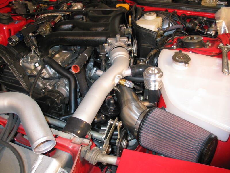
This is the GM IAT sensor mounted in my intercooler pipe.
This is a bit of an older pic, but not much has changed.
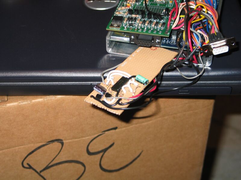
Thats the table switching circuit I mentioned.
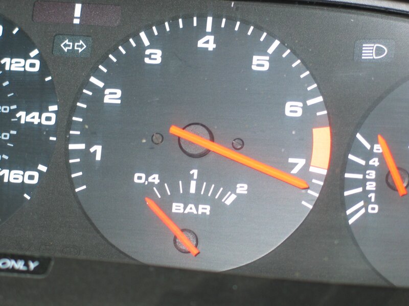
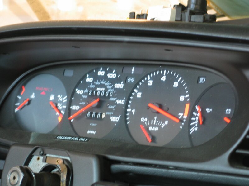
Testing the tach output (I dont think ive posted these yet...). Contrary to popular belief, the tach itself seems pretty accurate. Its slightly off around 3000RPM (maybe off by 1-200 RPM) but its bang on higher than that, all the way up to 7400RPM here.
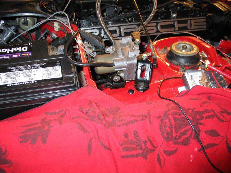
GM boost control solenoid in its new home.
This is the GM IAT sensor mounted in my intercooler pipe.
This is a bit of an older pic, but not much has changed.
Thats the table switching circuit I mentioned.
Testing the tach output (I dont think ive posted these yet...). Contrary to popular belief, the tach itself seems pretty accurate. Its slightly off around 3000RPM (maybe off by 1-200 RPM) but its bang on higher than that, all the way up to 7400RPM here.
GM boost control solenoid in its new home.
07-28-2006, 02:14 PM
#251
Burning Brakes
Join Date: Nov 2003
Location: Baltimore MD
Posts: 962
Likes: 0
Received 0 Likes
on
0 Posts
Dude, I think you've got a serious vacuum leak there...and you're going to blow your engine running it that high!!
Seriously though, awsome project! I'd be interested in seeing how it all turns out. Those things seem to have a ton of functionality built into them.
Seriously though, awsome project! I'd be interested in seeing how it all turns out. Those things seem to have a ton of functionality built into them.
07-28-2006, 04:56 PM
#252
Three Wheelin'
Originally Posted by theedge
GM boost control solenoid in its new home.
07-28-2006, 05:43 PM
#253
Banned
Join Date: Aug 2004
Location: seattle, washington - usa
Posts: 1,822
Likes: 0
Received 0 Likes
on
0 Posts
i'm curious, how does the megasquirt compare to the wolf3d ems ? i'm wondering if it's cheaper time-wise to just go with the plug-and-play solution;
http://www.lindseyracing.com/Merchan...ry_Code=WOLF3D
http://www.lindseyracing.com/Merchan...ry_Code=WOLF3D
07-28-2006, 06:11 PM
#254
Instructor
Join Date: Jul 2005
Location: Pasadena, CA
Posts: 227
Likes: 0
Received 0 Likes
on
0 Posts
I'm glad the 4017 by itself works.
Have you seen the development of the new high-res MSnSE code? It should give you significantly more stable idle AFRs, especially if you're running big injectors.
Have you seen the development of the new high-res MSnSE code? It should give you significantly more stable idle AFRs, especially if you're running big injectors.
07-28-2006, 06:17 PM
#255
Addict
Rennlist Member
Rennlist Member
Thread Starter
Originally Posted by IanS
I'm glad the 4017 by itself works.
Have you seen the development of the new high-res MSnSE code? It should give you significantly more stable idle AFRs, especially if you're running big injectors.
Have you seen the development of the new high-res MSnSE code? It should give you significantly more stable idle AFRs, especially if you're running big injectors.
 ) so I think ill be ok for now. I might try it at some point anyway just for ****s and giggles.