When you click on links to various merchants on this site and make a purchase, this can result in this site earning a commission. Affiliate programs and affiliations include, but are not limited to, the eBay Partner Network.
Thanks! I am changing my system now to remove the thinner line from oil tank back to ITB intake (I figured the vacuum on one of the intake feet (cyl5) would help remove any pressure in tank (which is does) but going to just take that line to main bigger (rear right wheel well) catch can now. So 2 lines as you have it to catch can and nothing to Intake.
I did have an oil/air separator (like a water trap on a compressor line) in line between the tank and ITB and it was catching oil .. but nothing was getting to the bigger less hard to drain catch can behind wheel - it was all just in the smaller oil air sep.
Engine is 11.5 comp 3.8 running flex fuel (motec) 340hp w 993 evo cams (should change those to 993 super sport or rsr I think).
haha .. cursed myself there (when I said last question) - I promptly did the tank to intake (suction) delete and ... straight back to my old problem, being ...
on idle (even on start up) oil immediately surges up the oil filler neck (if the cap is off).
1. only does it because cap is off? dont think so but could make it worse - I used to top up with engine running (dont most of us?) .. so this is wierd
2. I have too much oil in car - nope, checked twice and consistently compare dip stick (when warm, idling, flat etc..) to gauge and they agree - i run at 3 oclock (50%) oil level when hot (85% when track hot)
3. blocked pressure release valve on top of tank - replaced and checked
stumped .. again .. might be time to remove the damn tank again and work it out - but hoping it's something simpler (prayer of the late night wrencher)
4. I dont have the check valve on crankcase breather exit as gus has - could that be the reason ??
Anyways .. wow has this thread been around a few bends and back again .. feel like I'm lost in the forest and just saw a footprint and then after a minute realising ...it's mine!
Send help quick
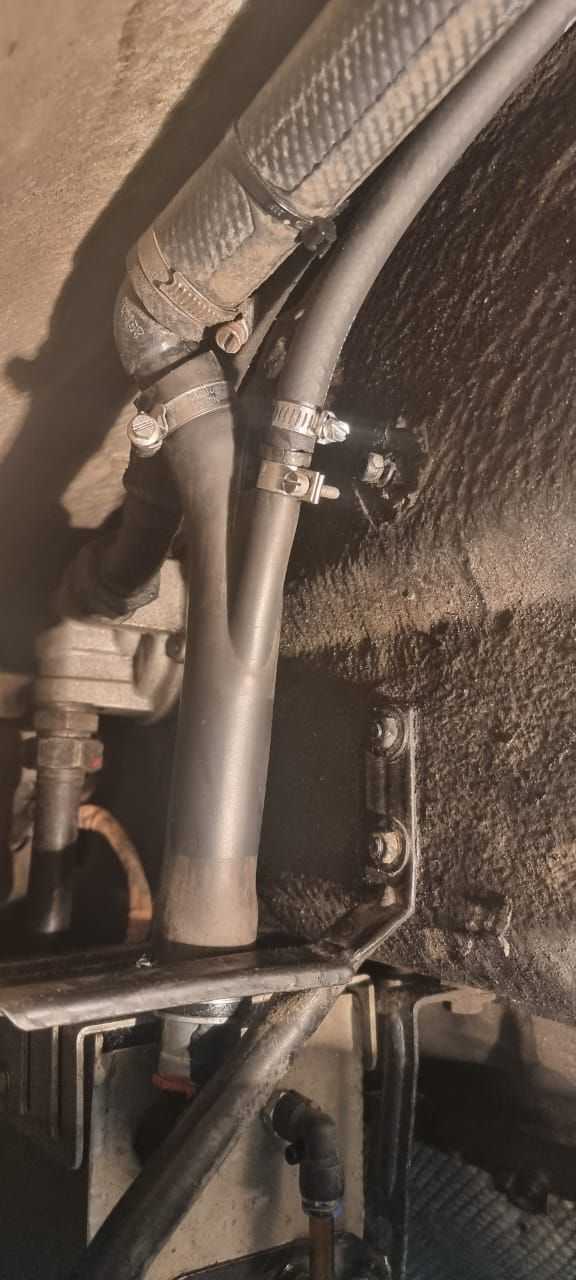
(was so proud of the pipe I found to add the suction line (that became the 2nd vent line) to the orig vent line
this is the way it was until this line became the thinner line Y'd into the pipe above
Last edited by HiWind; 08-11-2022 at 03:11 PM.
Reason: added pic
HiWinds- really baffled by your getting oil in filler neck on start up. Just does not make sense unless - too much oil in tank, breather lines are not right, or you have a really bad blow by issue. Add a 1way check valve will not help this issue as it keeps the engine from drawing oil back into the crank case, does not stop crankcase pressure from going to oil tank.
what is increasing the volume of oil in the oil tank to make it flow up the filler neck. My gut is telling me that you need to really verify the amount of oil in tank. I would pull oil out until it just reads on gauge/dip stick when cold. Then see what issues are.
Does this occur after oil has hit normal operating temps- should be worse as oil level is now higher.
keep me posted / I�ll be thinking on this.
sorry I explained badly - on startup BUT once warm (not on initial cold start) - I have verified oil in (in rad line drain etc..
I am thinking of running the crankcase line straight to the catch can and blocking the big crankcase intake on oil tank.
But I am thinking my top vent must be blocked (and yes there is blow by but engine is solid 340hp on dyno).
Thanks Gus et al - will report back
Thanks for all the valuable information.
I am in the same situation as well to minimize the oil from tank to intake.
I am currently on an ITB setup.
Pipe after butterfly wasnt connected neither blocked just zip tied as side.
Pipe before the butterfly remain the same connected to intake after filter.
Crank case pipe as stock setting to the tank.
I found Hastech Engineering has a vent vale added to stock crank case valve. https://lnengineering.com/hastech-en...separator.html
Wondering if any one has any experience on it?
I am thinking to install this vented valve and assume the oil will be kept in the crank case and only air come can escape.
Then add a filter just only on the top of the crank case outlet and block 3 pipe from the tank.
@Gus this thread has been such a great source of Information for a topic that seems like engine-voodoo - thanks so much! I�m current DIYing a TPC Supercharger install on my 993 and frustrated by the lack of documentation re: the oil breather / vacuum hoses and how they should be connected for the supercharger setup.
I totally get how the whole system works when it�s stock. What I don�t understand is your �two hoses to the catch can� setup. Why do you need two hoses if they are both going to the same catch can + vent to atmosphere? If you don�t have the manifold vacuum line, then why not just plug the 1/2� hose and have only the 1� hose going to the catch can? I.e. what�s the difference between the two hoses?
@CosMoon- I agree with you 2 vent hoses are over kill. I block the prebutterfly off as well as adding the one way valve to the main crank vent and have not had any oil issues with blow back into the intake manifold. I really think the one way valve in the main crank vent line is the trick. I use to have a small oil leak on the rear seal (pulley side), but now have no leaks and think this is due to the internal negative pressure within the crank case.
Ref the vacuum lines for the supercharge manifold. You are going to need a good check valve to be able to hold a vacuum. Since you are basically stock (except boost) you won�t need any vacuum except an assist for the brake line. This is assuming that you are not running any vacuum operated solenoids.
@CosMoon- I agree with you 2 vent hoses are over kill. I block the prebutterfly off as well as adding the one way valve to the main crank vent and have not had any oil issues with blow back into the intake manifold.
I really think the one way valve in the main crank vent line is the trick. I use to have a small oil leak on the rear seal (pulley side), but now have no leaks and think this is due to the internal negative pressure within the crank case.
Ref the vacuum lines for the supercharge manifold. You are going to need a good check valve to be able to hold a vacuum. Since you are basically stock (except boost) you won�t need any vacuum except an assist for the brake line. This is assuming that you are not running any vacuum operated solenoids.
Ahhh, I see! So in the past you had both the pre/post butterfly hoses going to the catch can, and now you only have the smaller one connected and the larger one is blocked - Correct? So having both was really just for redundancy?
As for my vacuum setup, I don't even need the brake line because it's a 993 C4 with the electric pump for the brake vacuum in the frunk. So I have the small vacuum barb -> check valve -> climate flaps in front of car
For the large vacuum barb on the intake, I'll either:
1. block it off
2. connect it back to the carbon canister by way the electrically actuated valve (as it is in a stock 993 engine)
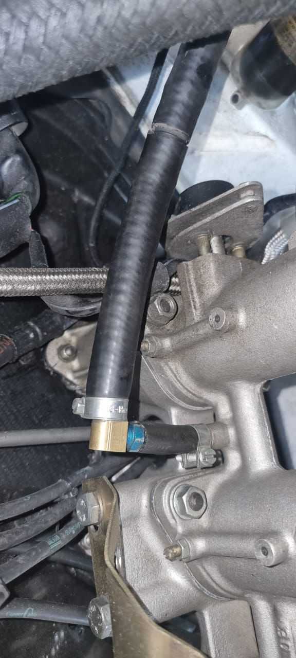
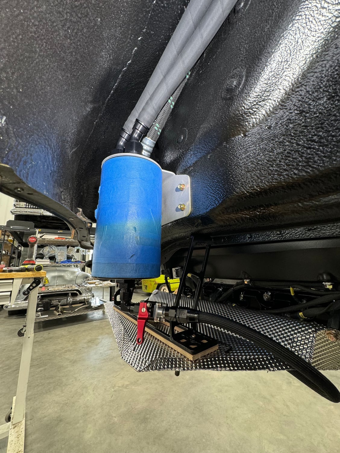
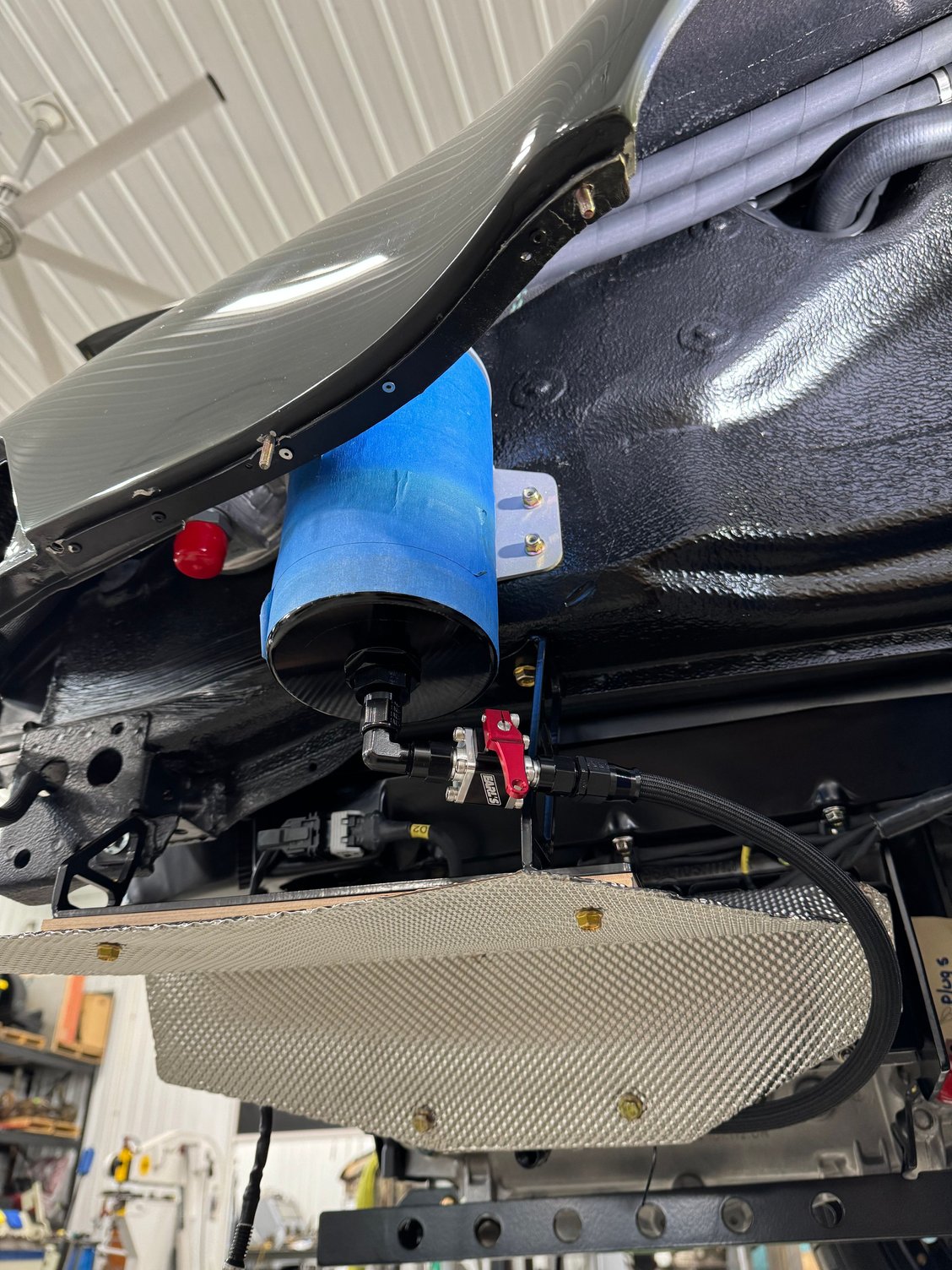
I�ve been lurking in this thread for awhile and developed a nice catch can setup for a backdated 964 project at my shop. Used a Vibrant bullet catch can, -12 hoses adapted to the factory rubber hoses coming off the oil tank, plus a ball valve with a drain line that passes thru my custom engine under tray. Awaiting exhaust to arrive back from Jet Hot to start the engine up and test out.
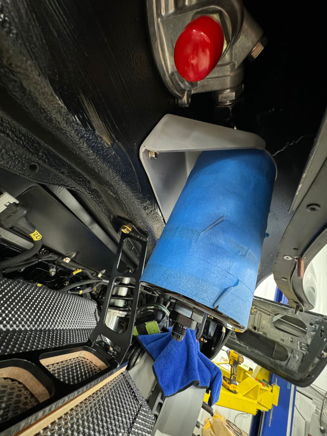
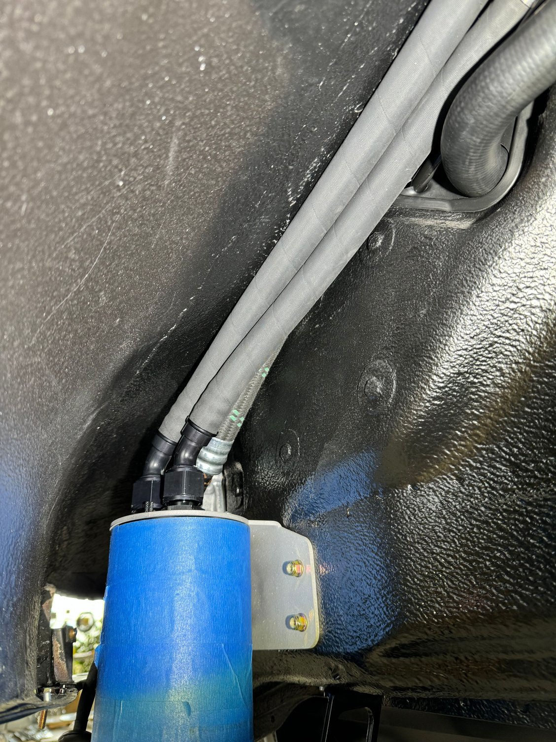
Custom mount to hold a Vibrant Gen 3 catch can. Mounts on existing fender support bracket studs set in the inner fender. Riv nuts added for the rear mounting hardware. Added a ball valve and drain line. Drains thru the engine under tray via a pass thru AN fitting. Hoses terminating at the catch can. Vent lines routing along the oil console line. Utilized stainless hose barb adapters to connect the -12 hose to the factory rubber hoses. Hoses terminating at the oil tank.
I never thought about mounting it that low. Seems like a good spot and makes sense. Advanced/Autozone carries a nice black billet can with bracket that looks like it would fit perfect in the engine bay. My Japanese 964 came with a catch can made from an old paint thinner can bungied to the engine carrier. I kind of like the old school hot rod look of it and haven't been keen to change it.
very nice work, but I�m still left with questions on the function of each of the hoses.
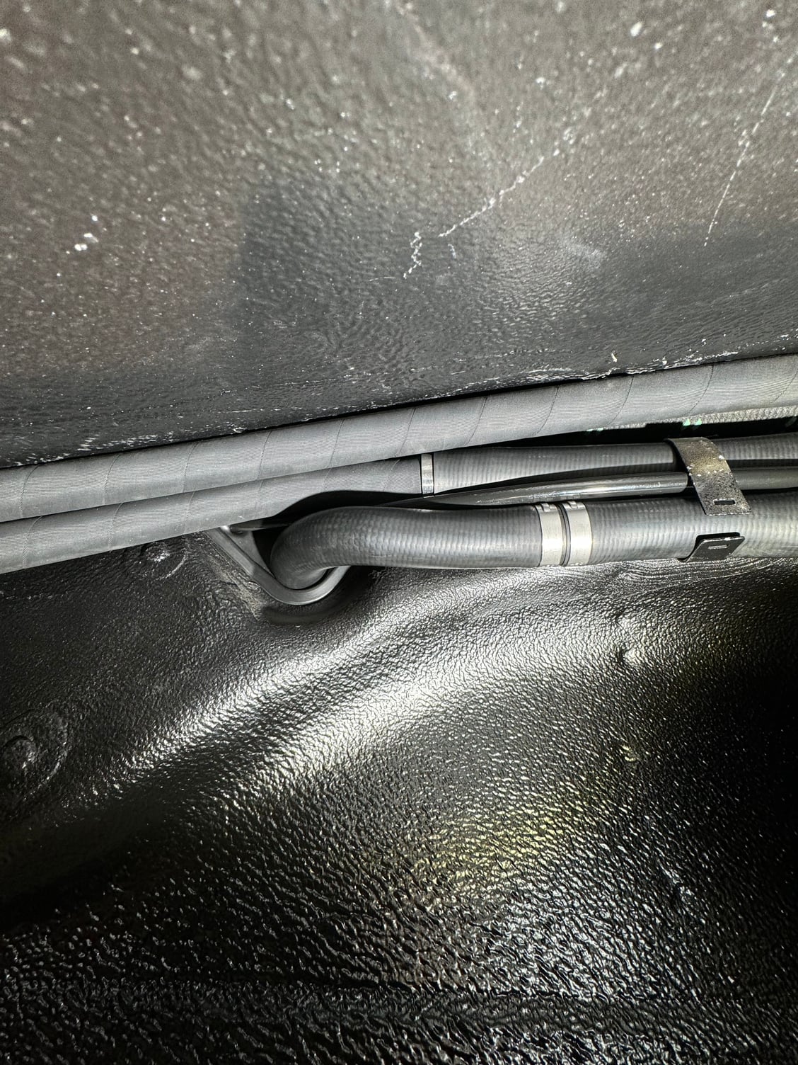
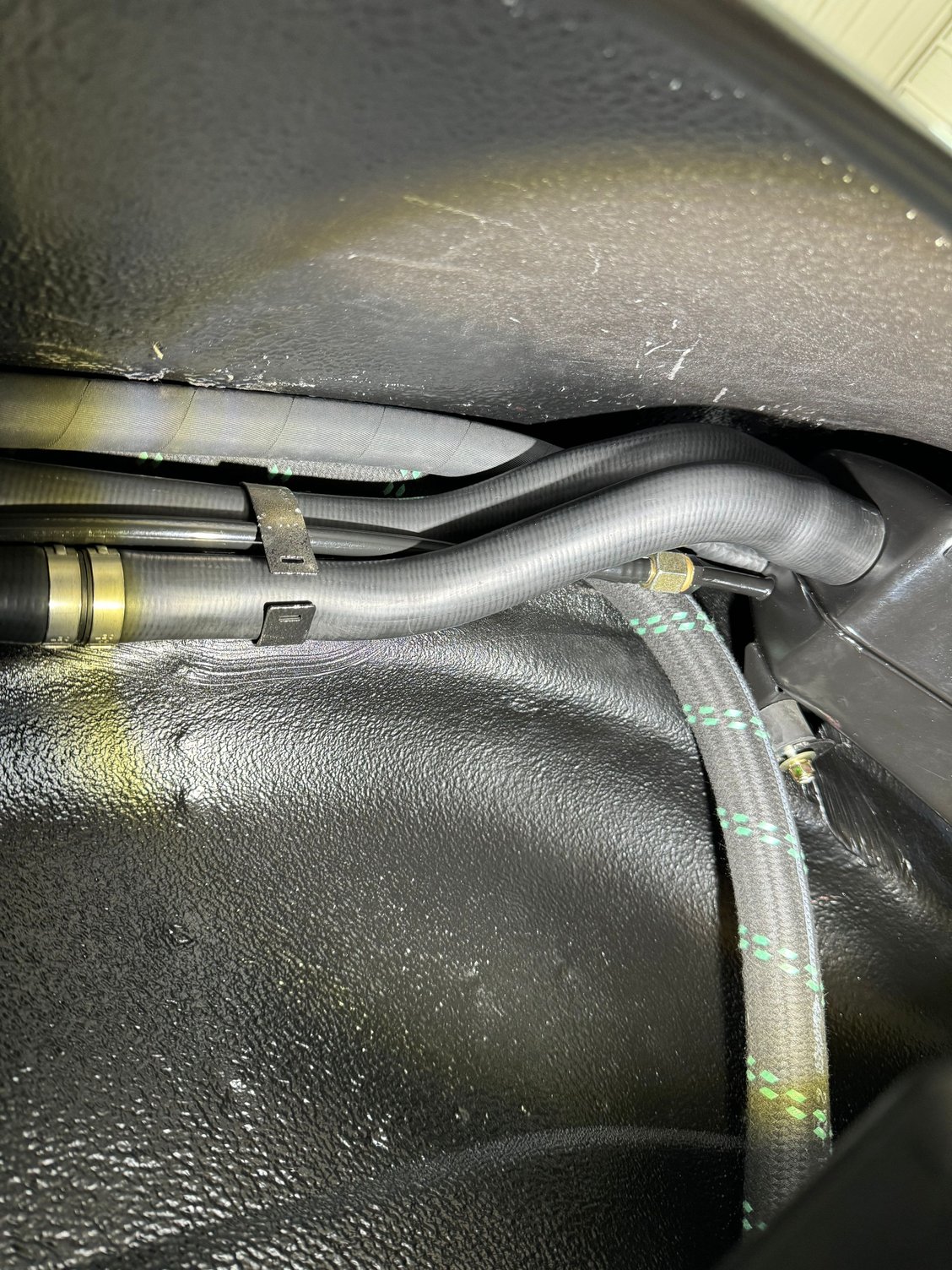
Why 3 hoses to the catch can instead of two? Do two go to the oil tank and one to fresh air?
the two hoses from the oil tank are redundant - correct?
Did you fabricate that engine tray as a one-off part?
It looks stamped!
Hand made. Traced the original plastic transmission section then made my own design to wrap around the heat exchangers and cover the engine cases. Formed from 3003 Aluminum sheet with a bead roller, then some hammer formed indentations.
Originally Posted by CosmosMoon
very nice work, but I�m still left with questions on the function of each of the hoses.
Why 3 hoses to the catch can instead of two? Do two go to the oil tank and one to fresh air?
the two hoses from the oil tank are redundant - correct?
There are only 2; the photo is misleading. You're seeing the oil line that goes from the oil console to the oil thermostat in the back ground. The 2nd line is over kill since one is obviously on the small restricted vent hole but I figured 1 more can't hurt. The Vibrant Gen 3 tanks can be assembled in two units, one tank that is sealed, with 2-3 lines inputting into the tank, then a crossover line into a vented catch can. This canister I'm using is a 1.5 liter vented unit, which I believe is more than enough if this motor ever gets worn out and starts spitting oil.

 08-09-2022, 03:28 AM