When you click on links to various merchants on this site and make a purchase, this can result in this site earning a commission. Affiliate programs and affiliations include, but are not limited to, the eBay Partner Network.
Cosmos - question - why not lose the complex Unichip device and 7+8 injector and go a custom ECU from Protomotive and upgrade fuel injectors?
In my experience this vastly simplified things and no cutting of wires required.
Sorry if this has been discussed before.
Good question!
Short answer;
1. cooling effect of the extra injectors
2. ease of tuning / live mapping to get dialed in 100% - by many tuners not just a Todd and a couple of others. This also gives more control and less of a feeling of �trusting black box�.
3. It�s really not very complicated (IMO). It�s tapping 2 wires, and splicing into 4 others. It�s one wire and a vacuum line between the ECU and the engine bay.
4. It�s how the system was designed and how it�s evolved over the past 20 years.
long answer:
What you describe was my original plan, and Todd has already done a tune on my chip so it�s socketed and I have the burner for the chip so I don�t even have to send my ECU back and forth to Todd, I can send him logs and he can just send me .bin files over email. We�ve talked about it.
That was my plan until this summer when I spoke to the main engine guy (Steve Scott!) at Auto Associates who has done 30+ TPC installs with no problems, including track cars running w/o intercoolers, and who has worked closely with the guys at TPC to make improvements to the system over the years. He pushed hard for sticking with the system �as designed�. To elaborate on the advantages I listed:
1. The extra injectors act like a meth injection - the atomized gas gets in early enough that it�s able to have a cooling effect on the compressed air (the regular injectors are closer to the pistons so can�t do this)
2. adjusting the timing/injectors off of MAP pressure is better than interpolating the MAF reading to determine boost (I don�t have any proof of this - just what I�ve heard)
3. the Unichip comes with an amazing (and massive!) manual. The whole first half of the manual goes into tons of detail on engine mechanics and theory. Chemistry of fossils fuels. Pros and cons of various methods of AFR measurement. So much stuff, it�s clear they are passionate about engine tuning and it�s all written for shop guys - most of their end-users probably never read it. They�ve been working with all kinds cars/engines. I felt much more comfortable with the hardware and software after reading the manual.
4. ease of tuning. There�s countless threads about the debate between using the stock Motronic or a piggyback system, or Motec/Emu/etc replacement ECU for a modded engine (I was just reading a great one from the 964 forum from 2006 with Geoffrey Ring, Colin Belton, LorenFB, Adrian Streather, et al. Having a very �spirited debate� of 200+ posts on the topic https://rennlist.com/forums/964-foru...upgrade-6.html)
The upshot of all of these discussions is that while the Motronic should be able to do it all, it�s a real hassle to tune, and there�s very few people who know how to do it. Certainly the opportunity to �live-tune� while it�s actually running on a dyno is not there. With the Unichip it is, and its way easier to find a tuner who can do it. This means there�s no compromise at any point in the tuning. No saying; ��this could be better but I�m sick of going back and forth with Todd to get it perfect�.
The TPC extra injector/piggyback system was worse when there was just one injector and used the SplitSecond box, but, by the accounts I�ve heard it�s very solid now.
I�ve done a lot of electronics as a hobby and I�m very confident that I can soldier, shrink-wrap and cloth-harness tape my work to the point that it will be both electrically rock-solid and visually clean. Especially in the rather tame environment that exists under the drivers seat where all the wiring work gets done!
given the benefits listed above, I think the couple of hours of wiring work I�ll have to do will be worth it.
i was 100% in the �no extra injectors� camp, but changed my mind, and may yet change it back! I�m trying to be objective about it and not get too attached to one strategy vs another.
Last edited by CosmosMoon; 12-22-2023 at 12:00 PM.
I have completed the wiring to the ECU!
I plugged the Unichip harness into the "bypass header", double checked all of the continuity with that header in place, connected the battery, started her up, took her out, and it's all running normally! ...as it should since with the bypass header in place the wiring is essentially in it's original state, unless I f'ed something up
I was super careful and double and triple checked everything as I went. With the right tools and a little patience it's not difficult.
Some notes:
1. Because there are a lot of wires with the same colors, you really need to be able to trace the wire all the way from the connector back to where you want to cut it. Therefore, I removed the screw on the back of the ECU harness connector hood and used a small flat-head screwdriver to pry the connector out of the hood. Then wiggled/slid the hood down the wiring loom about 6 - 8" and removed a bunch of the (non-adhesive) cloth tape. The way the tape goes on is with over-lapping short pieces running one way, and big long piece running from the non-ECU side overlapping everything. Removal is very easy, and it will be easy to put it back the same way. I traced the wires back to where I planned to make the cuts / connections, and marked them with a paint pen or some wire wrapped around them (or tape) and then put the hood back up by the connector so I had room to work. (Sadly no pic of the hood pulled down away from the connector, but you can kind of see what it looks like with the MY95 connector in this thread: https://forums.pelicanparts.com/pors...move-them.html).
2. The crank sensor +/- wires are inside of a shielded housing. I sliced the housing length-wise to keep the shielding continuous - I'm not totally sure where the shielding connects to ground, but there's a black wire inside the shielding that carries a ground for the shielding - you leave that intact.
3. In all my time doing hobby electronics, I never had one of those flexible-neck wire holder things, but I bought one for this project, and so glad I did! They hold the wires very steady and in perfect position to get a nice clean solid soldier joint. Makes it so easy. One of the best $20 tools I've bought - don't know what took me so long.
4. My post above was incorrect on the number of connections - it's actually less. Only 5 wires from the ECU get touched (3 get split, 2 get "tee-ed" off). I have chosen to also tee-off of the Tach signal wire for data logging with the LM-2. For the "tee" connections, I chose to shave away the insulation on the sides of a small section and leave the wire intact, soldier to the exposed wire then wrap the joint. The downside to this method is you can't use heat-shrink, and I'm not a fan of electrical tape for stuff like this. I found this stuff called "Shrink-n-repair" that's kind of like a heat-shrinkable electrical tape. you peel off an adhesive backing, wrap it around the wire, then heat-shrink it. This was my first time using it... It's more bulky than heat-shrink, and a bit of hassle to use in the tight space of the wiring loom, but the end result feels nice and solid.
5. It's good to have a mini/micro heat gun for the heat-shrink, and some foil or flexible metal to use as a heat shield for the rest of the loom.
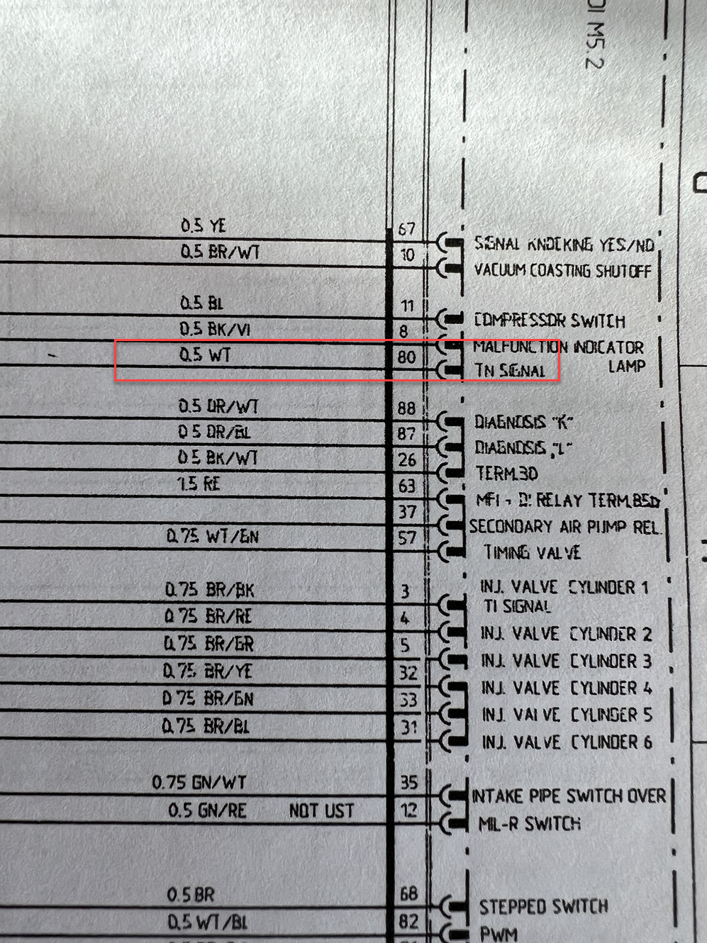
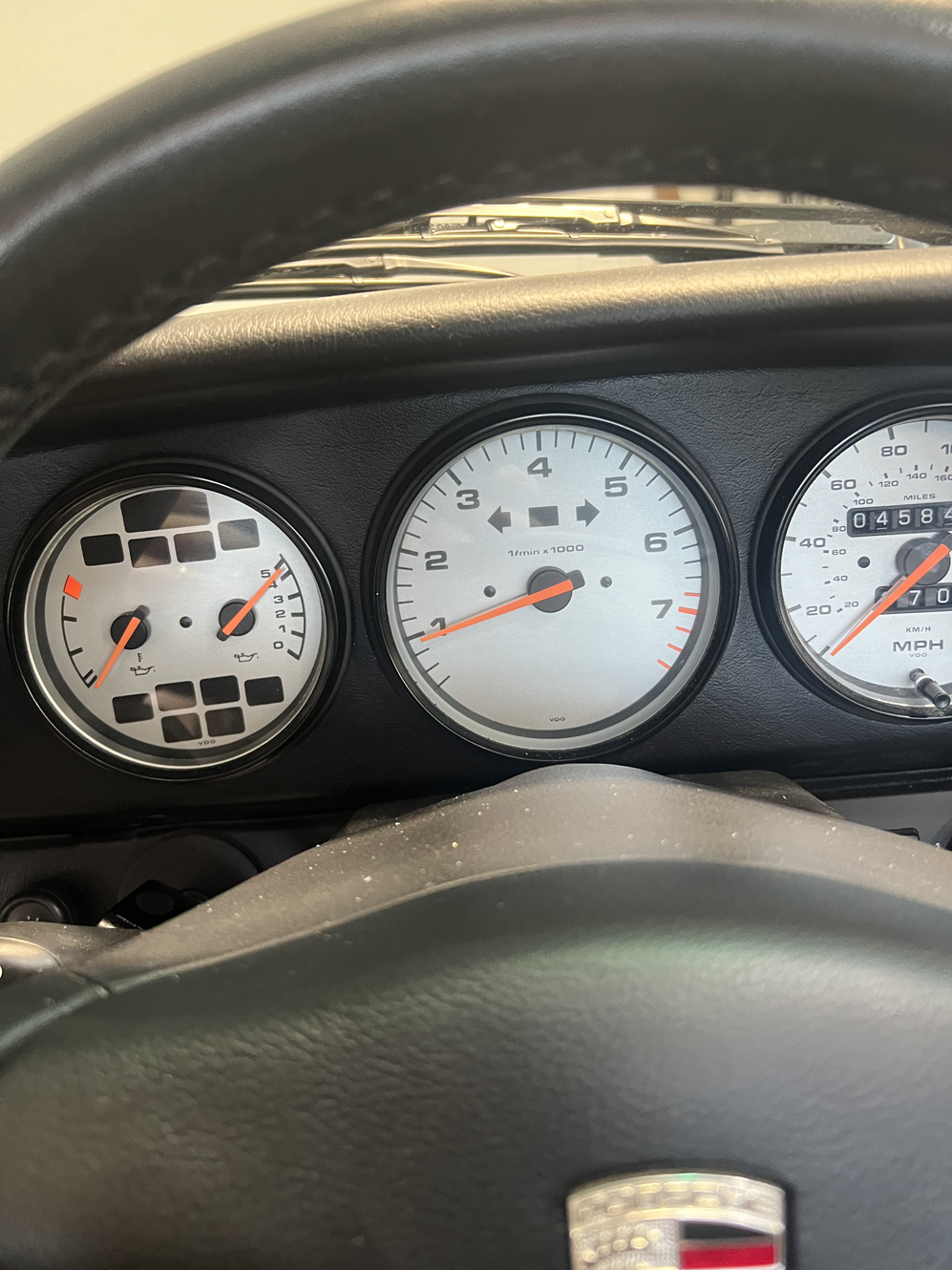
6. For some weird reason some of the color-codes on the wires are incorrect on the 96+ USA 5.2 wiring diagram! Thankfully none of the wires that I was working with were wrong but some of those around them are. E.g. The tachometer cable - listed as BK/VI (black /violet) for MY95, and listed the same way at the tachometer end of the wire for all models, is shown as White in the 96+ wiring diagram. Similarly, the O2 sensor wires are listed as Green in the 96+ wiring diagram, but if you look at the ECU harness for pins 76 / 77, and look at the connectors in the engine bay, you see the wires are actually White. This slowed me up a bit checking and re-checking and cross-referencing sources until I finally accepted that the diagram in the service manual is incorrect. Here a pic that shows what I'm talking about re: the tachometer wire:
Pin 80 on the connector is definitely not White! It's BK/VI
This is the TPC wiring diagram with a few notes. Important to note that the pinout is looking at the ECU, so if you are looking at the disconnected harness on the socket side, it will be reversed. Another way to remember is that the big bundle of wires exits the hood on the 28/55/88 pin side. E.g. the Red/White power wire at pin 54 is totally buried under all the other wires!
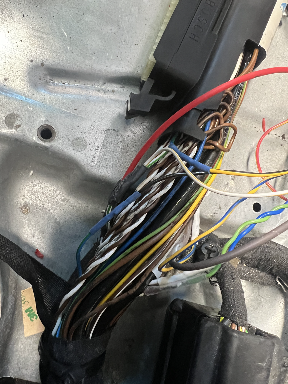
Here's some pics of the process. The first cut - the crank sensor. There's at least 3 of these shielded wires in the loom, so be sure you get the right one before cutting! You can't see the shielding, but it's in there - hidden behind that black wire.
The "helping hands" make for nice connections - solid, shiny joints!
Having these "acupuncture needle" style probes is great for doing a final check that you've got the right wire before cutting. This is the Green/Blue MAF signal wire from pin 17. With these probes, you can press the needle into the insulation just a tiny bit and get a continuity signal. When you pull the needle out, the hole is so tiny it seals itself.
(because I checked so many times, I never actually probed the wrong wire, but it's important to be sure!) The orange wires were just scrap pieces I used to tag the wires that needed to be cut, and got removed after I made the connections.
Almost done. All connections made, and heat-shrink has been shrunk. You can see that "Shrink-n-repair stuff on the Green/White TPS wire on the left side of the wire bundle.
This is the Unichip bypass header. Note that it has connection between the pins including the odd connection between the ground at pin12 and the crank- at pin 8!
All wiring checks complete - I put back the ECU to do a test drive. When the whole project is done and everything is working, I'll re-tape and clean up the wiring loom, put back the missing end-cap from hood and the zip-tie that holds it on, and clean up / wrap the branch for the Unichip.
Sadly because my Unichip is used, the wires on the harness are very short! I made a pigtail for the "boost" signal, so I can connect it to a gauge later. The connector for the Turbo module is out of frame to the right, but it's all wired up.
All systems normal. Starts and runs same as ever and no CEL
Next step is to run the fuel injector wire and vacuum line to the engine bay. I may also try running it with the Unichip connected and my laptop connect to the Unichip. The software lets you monitor the various input in real time, and since there would be no boost, the car should run normally.
After that it'll be time for the Supercharger! Sadly I won't have time for this until after the New Year.
Cheers, and Happy Holidays to everyone!
Chris
Last edited by CosmosMoon; 12-22-2023 at 06:47 PM.
Hey all - quick question on wiring�
I was thinking of running the intercooler water pump on the same power as the fuel pump. Thoughts?
Ignore this dumb-*** question. I totally forgot the fuel pump was up front and thought the fuel filter was the fuel pump
I have come up with a much better solution for the wiring of both the extra injectors and the fuel pump... more on that in a post coming soon!
Last edited by CosmosMoon; 03-09-2024 at 07:55 PM.
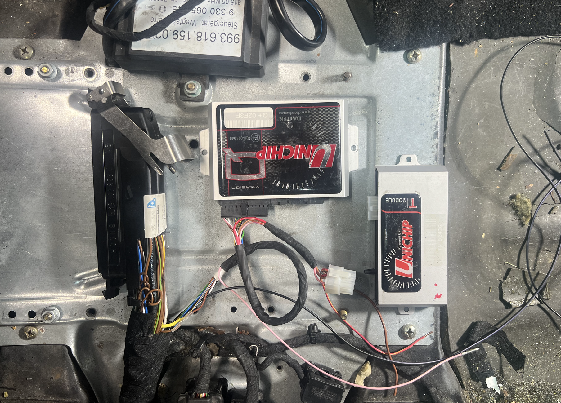
Incidentally, the big Unichip manual says repeatedly to installers; "always be proud of your work". I wasn't at all proud of the wiring due to the fact that the used Unichip had very short wires coming off of the connector. New connectors + wires were only $15 from Unichip, so I bought one and re-wired it. Much happier with how it looks now, and, again, everything is running smoothly with the bypass connector on the end.
Note that the loose pink wire is tapped into the MAP signal (boost), and the purple/black is tapped off the tachometer signal. These are for connecting loggers / monitors when the time comes. The loose brown wire goes to body ground, and the loose red/yellow gets extended back to the engine bay and connects to the ground side of the extra injectors.
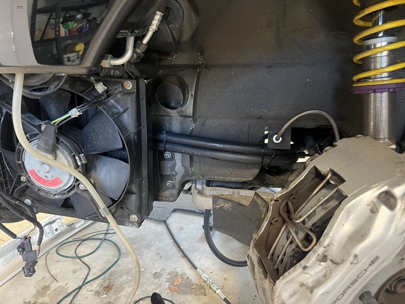
I spent a bunch of time over the weekend on the install, especially the radiator and running hoses. The fit for the hoses is tight in some places due to the AWD on my C4. With 2WD it would surely be easier, but as it is I'm happy with how it's coming out. Much like the pictures from TPC above. Their pics and the instructions gloss over some things though.
E.g.
1. I didn't realize the bolt they suggest attaching the radiator to near the bumper by the oil radiator is the one for the ceramic ballast resistor for the oil cooler fan! I (naturally) overtightened it and cracked the resistor. Not terrible, I figure it'd be best to always run the fan on full to help with the intercooler temps, so I will simply bypass the ballast resistor and have it run on high even when it's calling for low. I can always grab the wire from the hole by the headlight lever and put a new resistor on in the frunk if I decide I want it back...
2. The picture also doesn't show the diagonal metal tube/strut that my car has going from the tub to the radiator casing, but that's not a huge deal and actually locks it in better. I also put a small bracket on the back-side of the radiator for extra support - it's rock solid.
Intake manifold:
I removed my intake manifold without having to drop the engine at all. One thing I was super proud of was that I was able to disconnect the throttle linkage and the cruise-control linkage from the throttle body using only the fingers of my left hand - squirreled in behind the christmas tree. There's no way to get a second hand in there. This was a incredible feat and I think it was easily worth 500 XP ... maybe even 1000. If I had not previously dropped the engine and seen first-hand how those black plastic clip things sit on the throttle and how they come off of the cables after flipping them over and un-clipping, there's no way in hell I would have been able to figure this out. I was even even trying to look at it with a borescope while doing it, and that doesn't even work because there's so much other stuff packed around the throttle - you can't get a good view. It took about 15 minutes of cursing and fiddling but I got them!
I also had a complete brand new wire harness for the engine bay that I had (impulsively) bought back in the spring when I was having some low-voltage issues and I installed that. Also had brand new ignition coils that came with the TPC kit and installed those.
The wiring
I had read horror stories of guys struggling to get the wiring set up correctly with the extra injector(s) in the engine bay. In my case, with a varioram engine, the solution seems very simple. The flap-control wires for the varioram have a red/white (+) side that branches off of the same wire that gives power to the 6 "real" fuel injectors (the flaps, like the FIs are triggered from the ground side). I have cut the ground side on one of these now-unused varioram connectors, and connected the fuel-injector trigger (from the Unichip) to that, and then I'm using a male EV-1 connector at the end of the wire for the extra injectors and ... that's it! So simple, and the extra injectors will be using the same red/white power as the ECU, the Unichip and the "real" injectors.
For the power for the water pump, I can take advantage of the fact that I removed my SAI system. I can again connect an EV-1 connector to my unused SAI valve connector - which is currently wired for 40A(!) and gets power via relay from the main alternator power - so no problems with voltage drops on the fuel injectors or anything else. The trick here is to cut the ground trigger wire on the SAI relay in the engine-bay fuse panel, and permanently ground it. Then the water pump will run whenever the engine is on. (I'm going to swap out the 40A SAI fuse with something smaller - probably 10A). I'd love to be able to get the terminal out of the relay block for this and not cut the wire, but I've read about how to get those out and it sounds like a massive PITA involving a special fork-sort tool you put in from the back and hair pin from the front and pulling the wire at the same time... I'll just cut the very-easy-to-access and easy-to-repair-if-I-ever-need-to wire behind the relay ... thank you very much!
Last things I need to sort out are:
1. the vacuum hoses since I've learned all about what all of them do and how they all work, and I'm still not totally sure the best way to connect them ... might have more questions on that later today / this week.
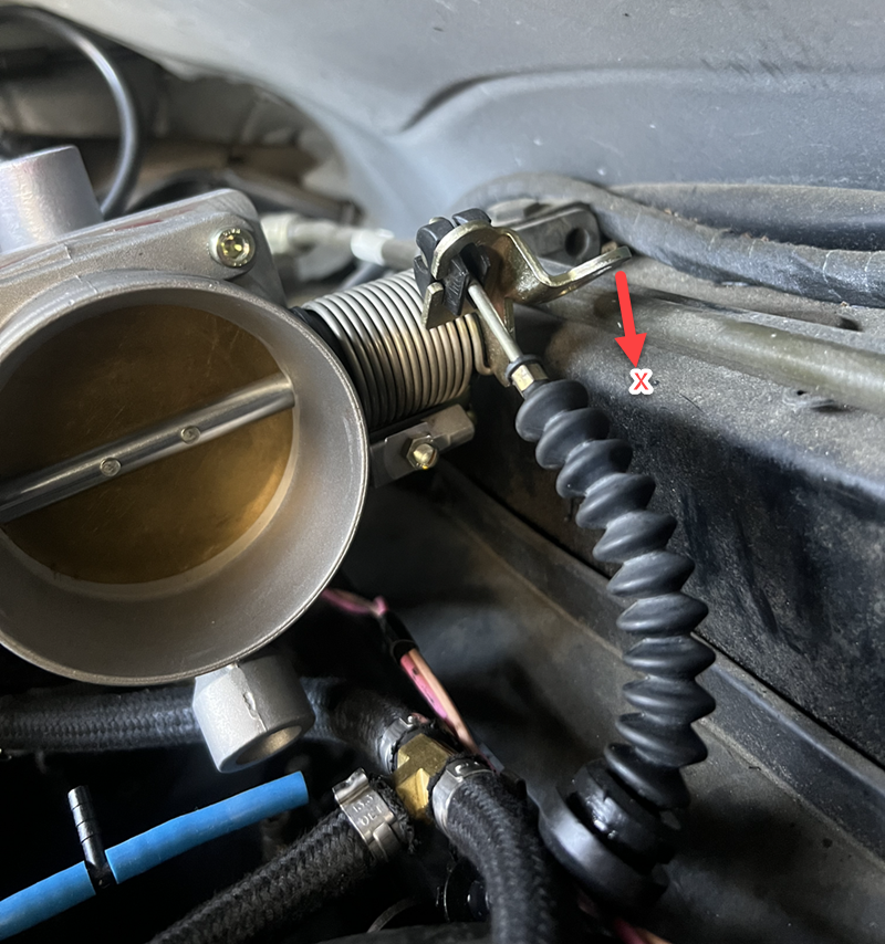
2. the throttle cable. Ah yes... the throttle cable. The first thing I've discovered from test-fitting is that the the cruise-control bit of the throttle itself hits the back of the engine bay when the throttle is about 50% open!
I don't know if this is only due to the new bigger version of the Eaton SC or if those with the older version have the same problem (the TPS, as others have mentioned, cannot be connected with the new version of the kit due to the larger SC - you need to unscrew the TPS and rotate it to get the wire clipped on, then rotate it back and screw it down). I can't imagine I've got any set up wrong here, the new manifold is solidly in place and the SC is solidly on the manifold.
Can anyone (with the newer black SC) confirm that their throttle linkage has been cut or bent to allow it to clear the back of the engine bay?
� ignore the cable in this pic, I was just playing around, it�s not really attached!
Last edited by CosmosMoon; 03-12-2024 at 05:01 PM.
Here's my attempt at further marking up the excellent diagram posted by Bill Verburg...
I wanted to understand how the air actually flows - especially as relates to the Oil Tank and the parts coming off the x-mas tree. One thing I never really "grokked" (and so I imagine a lot of folks don't either) is that vacuum breather lines before the throttle simply act as a SUPPLY for filtered air - they might suck air in, but not really, they are more used to supply air. These are yellow in the diagram, and the yellow box is the big rubber intake "snorkle" after the filter and before the manifold.
The running engine + closed throttle is what creates the most vacuum, so the the real "sucking" vacuum lines must connect to the intake manifold after the throttle. These are red in the diagram, and the red boxes represent point on the intake manifold.
Questions:
1. One thing I'm not totally clear on though is that is seems like the intake manifold can just constantly pull air in by way of the oil tank (hoses 1 & 2) - even when the throttle is fully closed. Does this make sense?
2. ...and if that's the case then what happens in the TPC setup where the oil tank is simply connected to a little air filter via the small tube (1) and not to the post-throttle manifold?
3. ...and why would you even need that hose (1) to have the little air filter on it when the filtered air can get in/out of the oil tank by way of the larger hose (2) connected to the snorkle? I.e. what purpose does hose #1 serve if it's not connected to the intake manifold.
Hose #3 is only used to source air for the venturi effect of the "sucking jet pump" ... still might be useful if you have a C2 for the brakes, but probably not needed for the C4. More info on how these work can be found here: https://www.bimmerfest.com/threads/h...t-fail.578766/
Last edited by CosmosMoon; 03-13-2024 at 10:38 AM.
Cut the cruise control tab off.
No other way.
Also - if you are using the stock engine lid / spoiler - you will need to cut some sheet metal from that as well.
And most probably drop the engine a few mm with some large washers under the engine mounts.
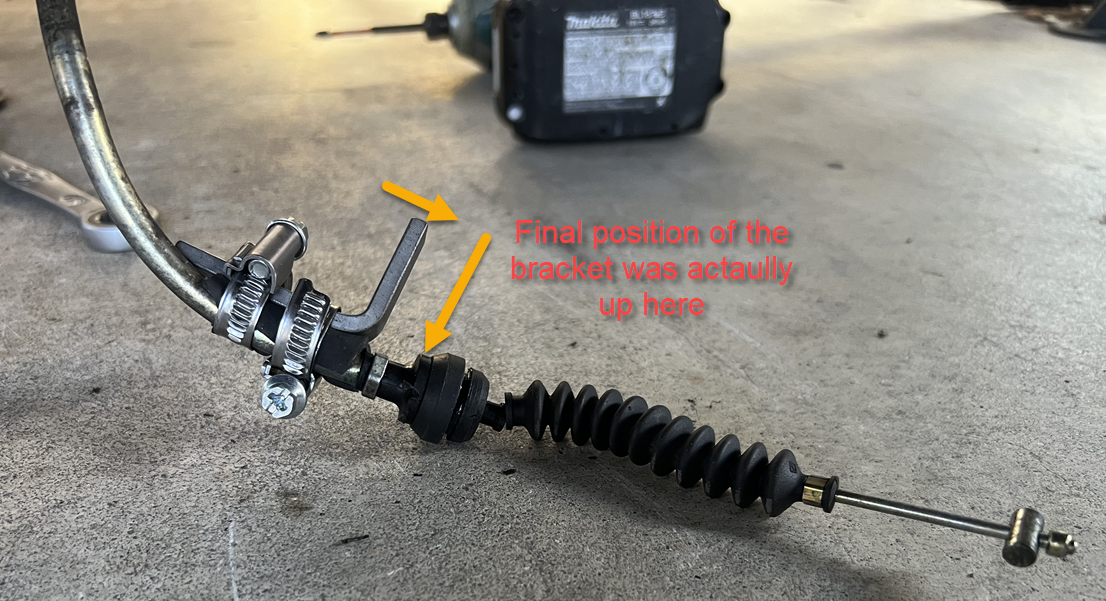
You need to adjust the position of the L bracket on the throttle cable until it correctly tensions the cable. Will take a few times to get this right. leave the intake manifold off while you do this.
Recommend you smoke test for any vacuum leaks as well.
Cut the cruise control tab off.
No other way.
Also - if you are using the stock engine lid / spoiler - you will need to cut some sheet metal from that as well.
And most probably drop the engine a few mm with some large washers under the engine mounts.
You need to adjust the position of the L bracket on the throttle cable until it correctly tensions the cable. Will take a few times to get this right. leave the intake manifold off while you do this.
Recommend you smoke test for any vacuum leaks as well.
Thanks haygee! good to know!
I have the duck tail, so I think I will have plenty of room, but I'll put the intercooler on today and check fit.
I know what you mean about getting the cable tension correct - I can see how that would be a hassle. I'm thinking of trying to fabricate a bracket with a 17mm hole to hold the cable end - like in the stock engine bracket. I've figured out where it needs to go, and should be pretty easy with a piece of bar-stock if I can get the bend-angle right, and then bolt it down with one of the (now unused) cruise-control bolts - I've seen other installs where this was done, and it seems like it help prevent a bend in the cable where it comes out of the metal tube - but the L-bracket clamped to the tube might just be a lot faster!
As for the vacuum lines, there's so few coming out of the manifold that I can't really foresee there being any problems. You'd have to make a pretty big mistake to accidentally hook up anything the wrong way or leave anything disconnected. I know how they want the oil tank lines connected, but I just want to understand why it's OK to do it that way vs the stock way (i.e. not connecting hose "1" in my diagram to the intake manifold). At the x-mas tree side, I have the same question as @kylejohnston1 in this thread: https://rennlist.com/forums/964-foru...r-install.html
...which is what to do with the vacuum for the carbon canister, and it's electronic valve? He draws a modified version of the TPC diagram that I think makes sense.
I don't have a smog pump, but I do have the vacuum control going to the Eaton bypass that's not shown in that (very old) TPC diagram, and should basically be a branch in between the check valve and the manifold... @Juha G - do you have anything to add? I saw your post here where you have a pic of exactly what I'm describing: https://rennlist.com/forums/993-foru...l#post11655766 ... but I'm curious about your experience with the carbon-canister hose and the fuel tank hose (see posts above).
Ok - this is my setup for the pipes and hoses.
My car is a 1994 model. I have a non varioram engine. I am using the Eaton Gen IV SC setup from TPC.
Single barb from the TPC intake manifold - vacuum hose to a few splitters and to these end points - Fuel press regulator, SC bypass valve, boost senor (I have my sensor in the engine bay. Using Zeitronix for telemetry - boost, EGT, air temp, and AFR).
On the elbow connected to the supercharger - I have the 3 port/barb version. The picture you have above is the 2 barb older version.
The largest barb goes to break booster.
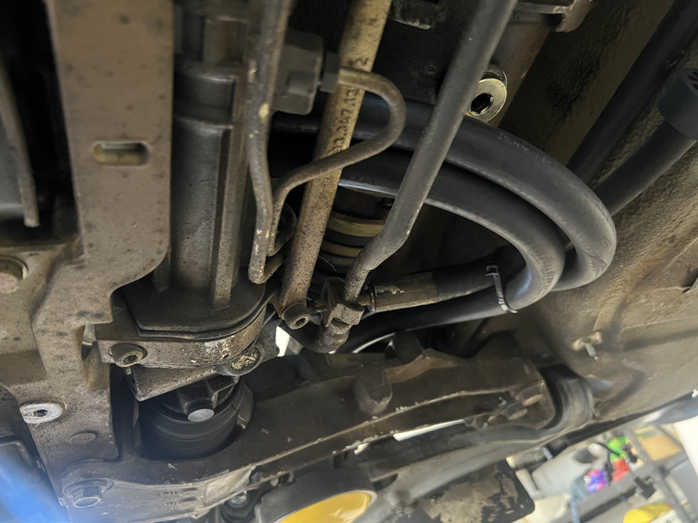
The middle medium barb - I have connected to the oil return line. Smaller oil pipe that runs from the right side of the engine bay.
Right smallest barb - I have this going to the bleeder valve - you refer to this above as the carbon canister.
I am thinking you can use a "V" connector to achieve this as well.
Just thought I would add to the discussion that Ive had my 1st gen TPC kit on my 993 for 23years (90k miles), installed by Colin Belton. It has methanol and a non-engine bay intake which has helped with too much motronic ignition retard when hot sitting in traffic. Still going strong, it just loves cold dry days :-)
Single barb from the TPC intake manifold - vacuum hose to a few splitters and to these end points - Fuel press regulator, SC bypass valve, boost sensor
Hm, you have the same type of black bypass valve on the side of your SC like the one in Juha’s photo? With the hose connected to the upper part of the bypass valve? And that’s connected to lower (boosted) port on the intakes? That seems rather odd since that bypass valve will only move when there’s a strong vacuum on that hose. The way you have it, the boost is controlling the boost. My understanding is that it should be a closed throttle creating a vacuum at the intake to the SC that opens the bypass valve and reduces the boost. That’s why Juha has his tubing set up that way. The hand-drawn TPC diagram doesn’t show this because it’s old and the older SC’s didn’t have a vacuum-controlled bypass.(afaik from the pictures I’ve seen)
Ignore that! Apparently this is the correct way to do it!
Originally Posted by haygeebaby
On the elbow connected to the supercharger - I have the 3 port/barb version. The picture you have above is the 2 barb older version.
Mine is the two barb one as well and has a ship date from TPC of 2019.
Originally Posted by haygeebaby
The largest barb goes to break booster.
The middle medium barb - I have connected to the oil return line. Smaller oil pipe that runs from the right side of the engine bay.
Right smallest barb - I have this going to the bleeder valve - you refer to this above as the carbon canister.
I am thinking you can use a "V" connector to achieve this as well.
hm, not sure what you mean by “bleeder valve” - the carbon canister itself is outside of the engine bay at the fuel tank. Maybe you mean the electronic valve for controlling it? The ‘98 stock engine basically has the carbon can vacuum line connected to the same vacuum as the brake boost - but there’s an electronically actuated valve to turn it off and on - the is “J” in the hand-drawing above - and it can be seen as the top black thing attached to the x-mas tree bracket in my photo of my intake manifold.
i wonder how many of the differences are based on MY of kit and MY of car. My friend Todd will be getting his SC’ed car back from the detailers in a day or two and I’ll be able to check out his install first-hand. (unfortunately I think he has an older kit w/o the bypass valve!)
I may just try calling the guys at Auto Associates today, or TPC and get their take!
Last edited by CosmosMoon; 03-14-2024 at 03:46 PM.
Hm, you have the same type of black bypass valve on the side of your SC like the one in Juha’s photo? With the hose connected to the upper part of the bypass valve? And that’s connected to lower (boosted) port on the intakes? That seems rather odd since that bypass valve will only move when there’s a strong vacuum on that hose. The way you have it, the boost is controlling the boost. My understanding is that it should be a closed throttle creating a vacuum at the intake to the SC that opens the bypass valve and reduces the boost. That’s why Juha has his tubing set up that way. The hand-drawn TPC diagram doesn’t show this because it’s old and the older SC’s didn’t have a vacuum-controlled bypass.(afaik from the pictures I’ve seen)
Sorry for doubting you Haygee! Called TPC, and while I didn't speak to Mike, the guy I spoke to said that the way you have it is indeed the way it should be connected, and that when the throttle is closed both the intake and the output side of the blower are under vacuum (makes sense I guess - there's really no place for the SC to get it's air from if the throttle is closed and the engine is running). It might actually work either way to be honest.. I'd be curious to see some other installs.In fact if the that bypass is completely disconnected, the car should drive fine it just stresses out the SC and uses more fuel, but best to do it the way TPC says to do it! They also seems to not care much about the carbon canister hose - i.e. just plug it, or hook up to the brake boost line, or not...
...and they said the small hose from the oil tank that you have going to your manifold should just go to one of those little air filters (you can see in the some of posted install pics above) and be left open to breathe.
That last one still has me a little confused - like why does the stock engine connect it to the intake?
Anyway, I think I'm all set now - last big hurdle is getting that throttle bracket figured out! I'm excited!
Cheers,
Chris
Last edited by CosmosMoon; 03-14-2024 at 03:48 PM.
A good way to get the throttle cable configured correctly is to take your cell phone and film the throttle body butterfly while you step on accelerator in the drivers seat.
Then adjust and repeat the process so you can see if the cable needs more adjustment.
Otherwise grab someone and have them step on the accelerator for you.
This process is a pita - and you might need to repeat about 3 or 4 times to get it perfect.
Make sure the L bracket is firmly attached - otherwise it can come loose and your accelerator pedal will bottom out.
Cell phone is a good idea! I have a couple of kids who'd probably help out as well
There's also that adjuster-barrel under the car where the throttle cable goes into the body, but IIRC, it doesn't give a huge amount of adjustment.
Thanks!
Slowly making progress...
Everything is bit more work than they make it out to be in the instructions. Even getting the hose onto the pump and getting the air filter onto the MAF intake tube takes some strong hands.
Fitting everything into the engine bay when you have the intercooler is like 4-dimensional tetris!
I am assuming those of you with the intercooler - like DocTock above - have cut the ISV valve mounting rubber off of the intake "snorkle" (aka "airbox") other wise it can't fit under the intercooler ...
and, if this is the case (and since it looks like most installs from the previous pics in the thread have the ISV mounted right next to the throttle body as opposed to hanging off the snorkle) I'm guessing that it's not really supported by anything other than the elbow-hose.
Also the instructions tell you that later model engine owners need an early model throttle body and airbox, but they don't mention that you also need to spend $130 for that little elbow hose for the ISV which is early-model specific (insane!) ... still waiting for that to arrive.
Another pro-tip not mentioned in the instructions; the SC pulley support bracket has to go flat against fan shroud. To get this to happen, you need to dremel off some bits of the plastic engine shroud near the left and right holes - once that's done though it fits beautifully.
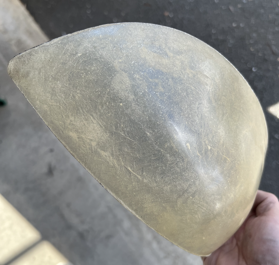
Next up in my litany of setbacks is this random piece of fiberglass they send to use as a block off for the engine shroud after removing the airduct.
How is this supposed to be attached to the engine shroud when you can't use the SC pulley bracket to hold it down against the fan shroud and when there's nothing to attach it to on the big engine cowling/shroud/air-duct? We are only left to wonder! If anyone has a pic of the piece installed behind the engine fan, I'd love to see it! I was thinking of simply drilling some small holes through this piece of **** fiberglass and the engine shroud, putting some speed-nuts on the shroud and screwing it down as a temporary solution until I can get a 3D scanner, scan the whole area, and then 3d-print something with a U-shaped lip to go around the engine-shroud side with little blocks on the engine side for tapping and putting in screws ... or something that actually makes sense! I may also see if I can do anything with the stock airduct in that location - haven't tried that, just thought of it now.
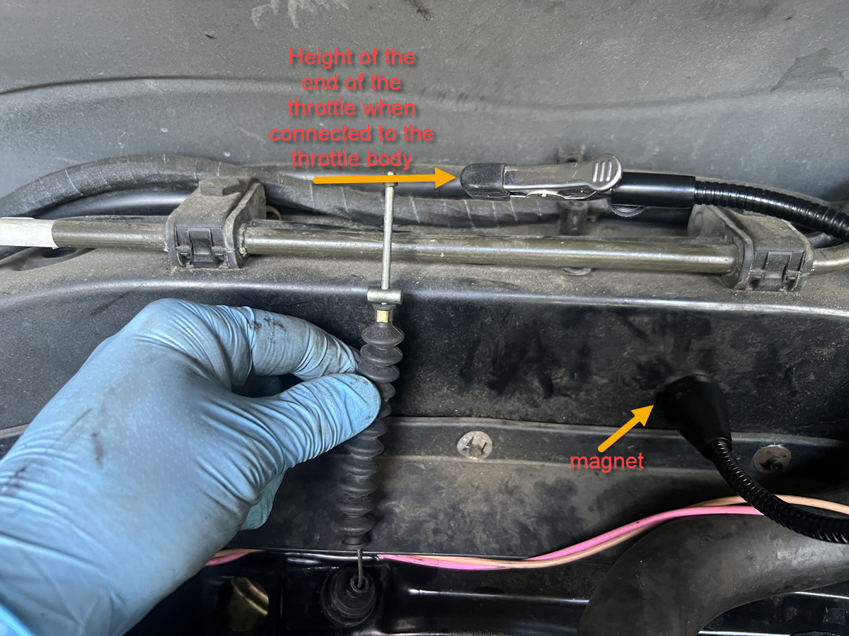
I did get the throttle positioned nicely. I used one of those "third hand" things I use for doing soldering and positioned it so that it aligned with the position of the end of the throttle cable when it's on the throttle body. Then I could pull the SC out and play with it, and still know where I needed the cable to be when done.
And lastly, my idea about using the SAI relay for powering the water pump worked great. I did the classic "bucket test" on the radiator and hoses to make sure it was all good and the pump runs when the ignition is on (and turns off when it's off!) That relay signal is actually kind of cool because it runs for a few seconds after the engine shuts off.. which is a reassuring reminder that the pump is running. My final wiring for this pump will be much nicer - this was just for testing! Those long wires went to the terminals for the SAI pump.
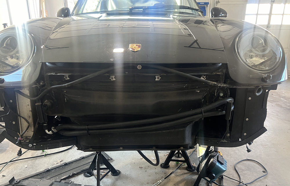
Now that the radiator checks out, I've put the front bumper back together - yeah! Looking like a real car again!
Just waiting on that little hose for the ISV to arrive from Rose Passion, some vacuum line splitters, and an adapter hose for the oil line hose to the mini-air-filter, and then I hope to be able to do final assembly and test it out! It's tough to get a sense of the positioning of the rear intake tube and ISV and cone filter without having that ISV tube due to the funny way it curves.
Last edited by CosmosMoon; 03-18-2024 at 02:42 PM.

 12-16-2023, 01:08 PM