When you click on links to various merchants on this site and make a purchase, this can result in this site earning a commission. Affiliate programs and affiliations include, but are not limited to, the eBay Partner Network.
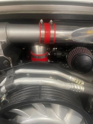
BTW, I was thinking that if you wanted extra cooling, it'd be cool (and easy?) to have something like this in place of one or both of those straight hose sections behind the bumper...
Cosmo - just some thoughts from my experience with the TPC kit.
- my kit doesn't need to have the ISV round mount cut from the intake elbow. If you source a longer intake pipe to move the elbow further to the right of the engine bay you might be able to avoid cutting this.
- isv should be mounted on the original location on the rubber elbow. There should be two pipes that support the structure. A smaller pipe for the ISV and the large pipe connected to the rubber elbow.
- you can use any generic silicone hose for the isv air duct. 20-30 bucks. Just find the right size right angle piece and cut to length.
- didn't have to cut any part of the stock engine / fan shroud to fit the SC snout support bracket. Did you adjust the angle of the bracket on the snout and try to get things to fit? Cutting definitely not required on my version.
- that plastic fan shroud that goes over the heater pipe cavity - paint it black - and you need to drill 3 holes that match the 3 screw holes on top of the engine fan. Then the SC snout support bracket goes over the lip of the plastic shroud. Then you put 3 screws through the holes.
- recommend you get the correct throttle cable distance with the intake manifold+sc+throttle body installed in the engine bay. The cable will be curved in an odd way. Helping hands won't help you here.
Other recommendations:
Inspect the two rotors in your SC unit. Ensure they are smooth and if they are Teflon coated - that they are not peeling. If peeling - you need to fix this before using the SC unit.
Change the oil on your SC unit before final install
Consider porting your SC unit
Recommend upgrading to a Clewett Engineering serpentine belt setup with the pulley mounted to the engine body- this gives perfect belt alignment and is an optimal configuration in my opinion
Do a smoke test if possible to help you identify vacuum leaks - save you a lot of headaches when trouble shooting problems
Upgrade your water pump to flow a greater capacity of water through the charge cooler - optimize cooling
Use a larger water hose pipe size for your charge cooler configuration - optimize cooling
For exceptional cooling covert to a interchiller configuration - user windydog has done this.
Hope this helps.
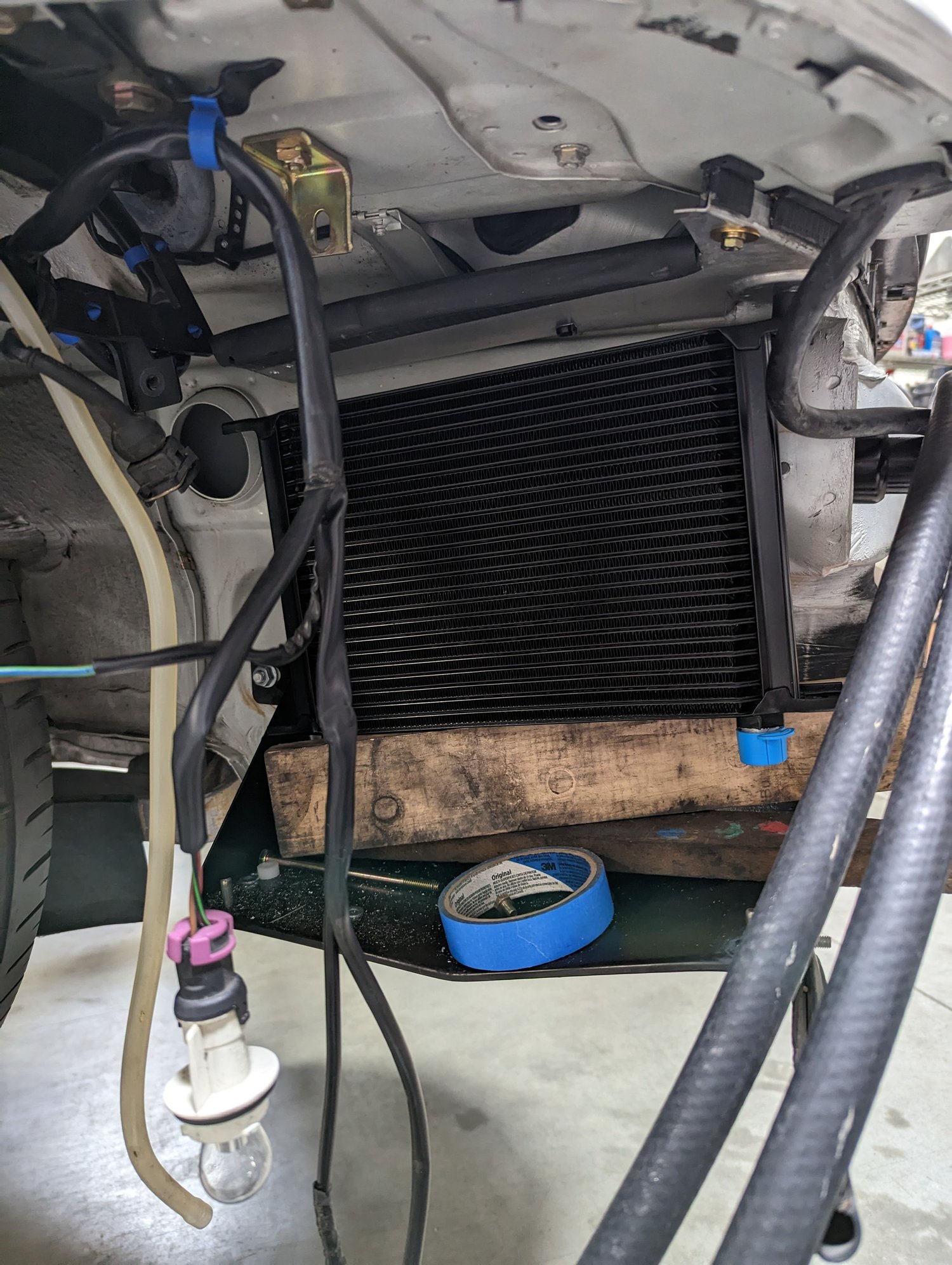
Also - why not mount your chargecooler heat exchange in the area where the AC heat exchange is?
Did you consider putting it in the location where the secondary oil cooler would go for better front on air cooling?
If I had the duck tail or RS spoiler I would consider mounting the heat exchange there and reduce the complexity.
Last edited by haygeebaby; 03-17-2024 at 01:27 PM.
Cosmo - just some thoughts from my experience with the TPC kit.
Hey man, I really appreciate all the time / effort to respond ... here 's my thoughts...
Originally Posted by haygeebaby
- my kit doesn't need to have the ISV round mount cut from the intake elbow. If you source a longer intake pipe to move the elbow further to the right of the engine bay you might be able to avoid cutting this.
- isv should be mounted on the original location on the rubber elbow. There should be two pipes that support the structure. A smaller pipe for the ISV and the large pipe connected to the rubber elbow.
- you can use any generic silicone hose for the isv air duct. 20-30 bucks. Just find the right size right angle piece and cut to length.
- didn't have to cut any part of the stock engine / fan shroud to fit the SC snout support bracket. Did you adjust the angle of the bracket on the snout and try to get things to fit? Cutting definitely not required on my version.
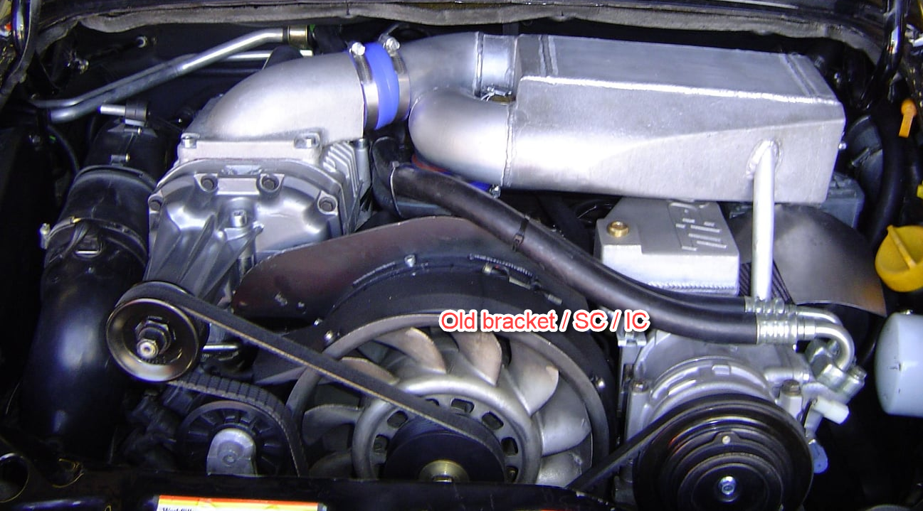
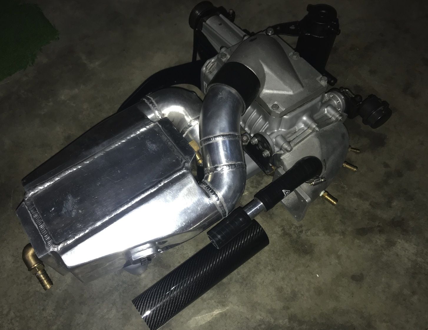
If the pic you posted way up at the top of the thread is your IC:
...that is very different from the current state of the SC or IC included in the kit these days.
The SC and IC in my kit looks like the ones posted by Newbian and DocTock (above) and you can see they both routed the air filter under the SC as it seems to be the best way to fit things given the size of the IC.
You will also notice they are using a different bracket design in the latest kits. The SC snout has a polished ring at the end and the bracket has an extra arm that extends out to the end of the SC and holds it at that polished ring-point. I bring this up only because of the new design could be the cause of a difference in fit on the fan housing (see below).
Originally Posted by haygeebaby
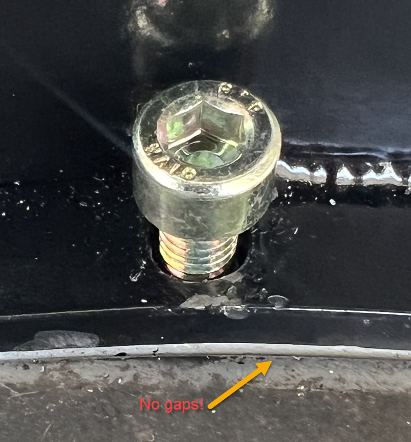
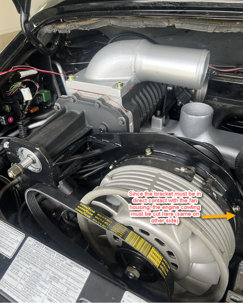
- that plastic fan shroud that goes over the heater pipe cavity - paint it black - and you need to drill 3 holes that match the 3 screw holes on top of the engine fan. Then the SC snout support bracket goes over the lip of the plastic shroud. Then you put 3 screws through the holes.
This is EXACTLY what I expected to have to do from the instructions. Unfortunately, this won't work because the bracket is a very high-tolerance fit to the fan shroud. I mean there is one and only one place where it can sit to get all three bolts in it, and that place is resting perfectly flat against the fan shroud.... and I mean flat! Here's a pick of the bracket mounted with only the outer two bolts, and the bolts are backed out about 2mm, and the fan shroud will not budge in any direction because of the angle of the holes around the circle. You certainly cannot lift it away from the fan shroud to fit anything under it. I mean, I'm happy with how exact the fit is, but you definitely can't put that fiberglass piece under it without making the holes on the bracket bigger for these two outer bolts. I've also included a close-up of the center bolt (with the washer removed) showing how tight the tolerance is for bolt vs hole (and how it's exactly centered). You can also see the same tight fit (nothing between bracket and fan shroud) on Newbian's pic above.
Originally Posted by haygeebaby
- recommend you get the correct throttle cable distance with the intake manifold+sc+throttle body installed in the engine bay. The cable will be curved in an odd way. Helping hands won't help you here.
I'd love to see a pic in the documentation of the throttle cable coming through the sheetmetal and connected to the throttle body! That would save folks a lot of time.
Mine is indeed at an odd angle, and it's basically nothing but that rubber / plastic end piece on the end of the throttle housing-pipe that sticks out of the hole. I'll post a pic. I did the basic fitting w/o the SC + throttle in the engine bay, then was able to use the adjuster barrel under the car to get it nice and tight once I actually hooked it up. It does seem like the cable runs very tight to the back of the engine pan, and at an odd angle, but I doesn't seem to be straining or rubbing anywhere. I'll try to remember to take/post a pic. The only pic of this I've seen in any thread, is this grainy one from WindyDog that uses his nicely-made custom bracket. Given that I feel like he and I ended up with the same positioning, I think I'm OK.
Hmm... studying his throttle cabel in this pic, it looks like his is rubber cable all the way to the end - mine is not. Mine has about 6" or so of metal pipe at the end bent in a kind of odd way. Checking AutoAtlanta site, I see they changed it for MY '96 and later.
Originally Posted by haygeebaby
Other recommendations:
Inspect the two rotors in your SC unit. Ensure they are smooth and if they are Teflon coated - that they are not peeling. If peeling - you need to fix this before using the SC unit.
Did that when I got it and it looked brand new and clean.
Originally Posted by haygeebaby
Change the oil on your SC unit before final install
Even on a brand-new one?
Originally Posted by haygeebaby
Consider porting your SC unit
Recommend upgrading to a Clewett Engineering serpentine belt setup with the pulley mounted to the engine body- this gives perfect belt alignment and is an optimal configuration in my opinion
Do a smoke test if possible to help you identify vacuum leaks - save you a lot of headaches when trouble shooting problems
Upgrade your water pump to flow a greater capacity of water through the charge cooler - optimize cooling
Use a larger water hose pipe size for your charge cooler configuration - optimize cooling
For exceptional cooling covert to a interchiller configuration - user windydog has done this.
Hope this helps.
I've been running the Clewitt for the past year. I'd really be cursing if I had to swap crank pulleys as part of this install now - LOL!
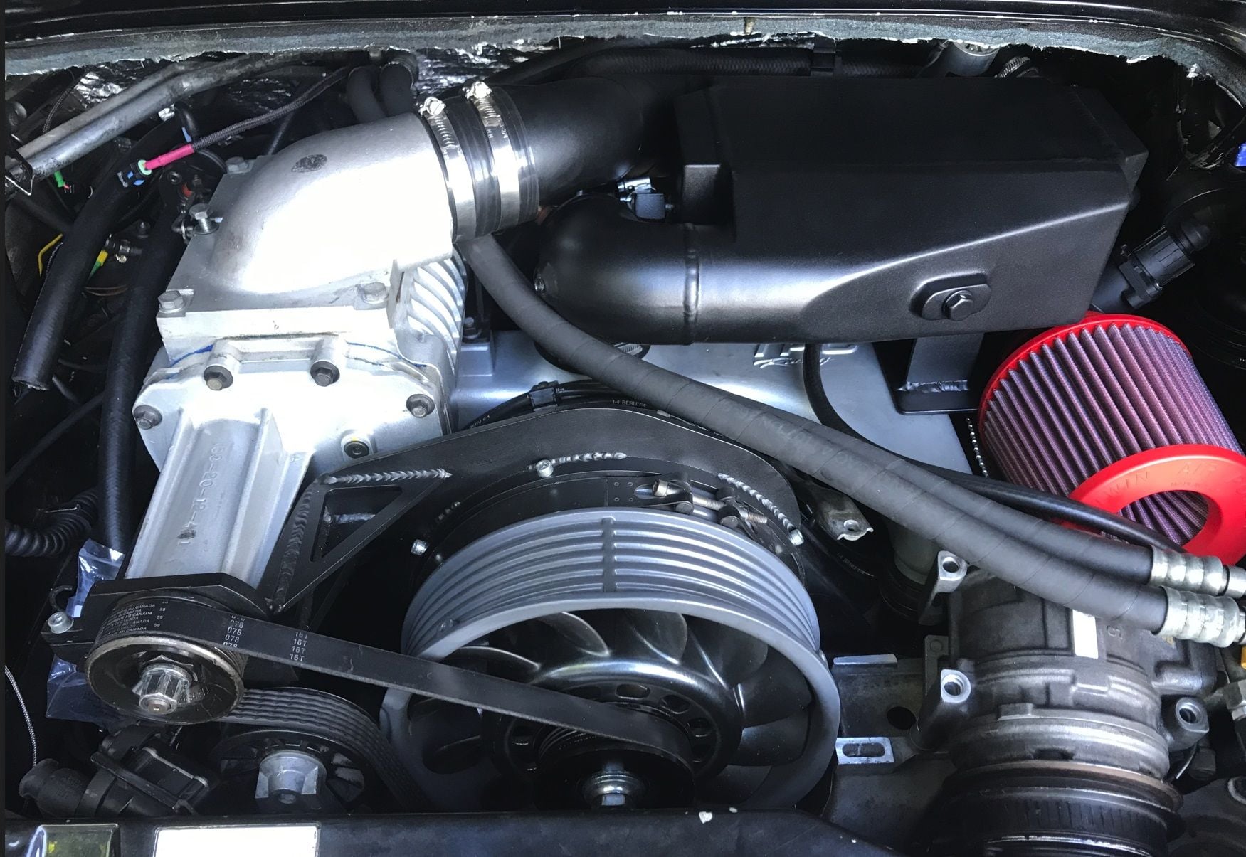
One thing to note is that with the new bracket you cannot mount the SC to the engine with the pulley on the SC - the pulley won't fit through the ring on the end of the mounting bracket. See Newbian's pic again the bolt to the left of the pulley on the end of the bracket is just to tighten it - you can't open up that ring. You have to put the SC onto the engine by sliding it into the ring from behind and down onto the studs on the intake at the same time, and then put the pulley on the end. Seemed tricky at first, but I'm used to now and it's not bad. I put the pulley on with the nut and then test-fit the larger belt I got for the Clewitt + SC. The fit looks amazing - perfectly centered / straight, but it's always hard to tell w/o the engine running, and the tensioner with the larger belt sits in the same place as it did with the small belt on just the alternator. I'm surprised I didn't take a pic - I'll post one ASAP.
Given the number of happy customers I've seen here and in-person with no intercooler at all, I'm not going to get super into the whole cooling thing right away
Originally Posted by haygeebaby
Also - why not mount your chargecooler heat exchange in the area where the AC heat exchange is?
Did you consider putting it in the location where the secondary oil cooler would go for better front on air cooling?
I just followed the instructions and the pictures posted above - they have it on the oil cooler side, so I did the same.
Originally Posted by haygeebaby
If I had the duck tail or RS spoiler I would consider mounting the heat exchange there and reduce the complexity.
I actually plan on investigating having AutoAssociates fabricate an air-to-air IC for me to fit under the ducktail - that will REALLY simplify things! I just wanted to get it up and running first with the standard configuration.
TPC, AutoAssociates, and that thread all say the smallest breather should be connected to the K&N air filter and open to air. But... based on this long discussion of the oil tank breathers: https://rennlist.com/forums/964-foru...-breather.html
... I have to wonder why it's not going to the intake (the way yours is!) and/or why more folks aren't using a catch-can or separator with the air filter. Obviously I'm being very patient and deliberate about this - just want to do everything right (and I keep having to order little bits and pieces which takes forever - LOL!)
Last edited by CosmosMoon; 03-18-2024 at 04:58 AM.
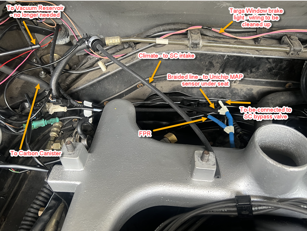
My vacuum diagram
I think since I don't need the brake booster connected that I will hook up the carbon can and it's control valve to that unused barb on the intake. I also think I might switch out more of those blue silicone hoses for the braided rubber. The braided ones are stiffer (less likely to kink) and they don't stretch as much so the seal is REALLY tight.
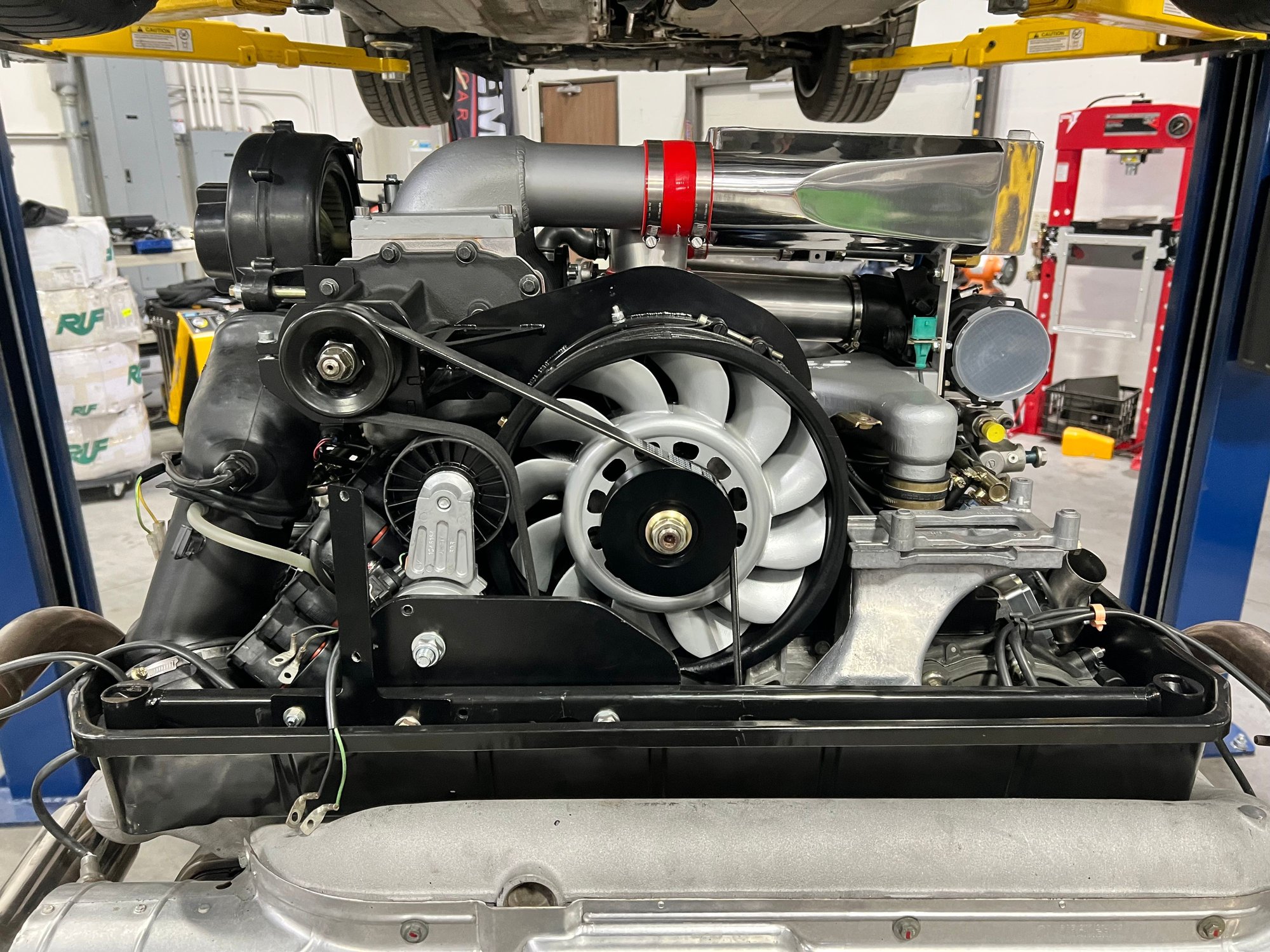
The bracket with the SC in place
...just to give a clear picture of how it all goes together
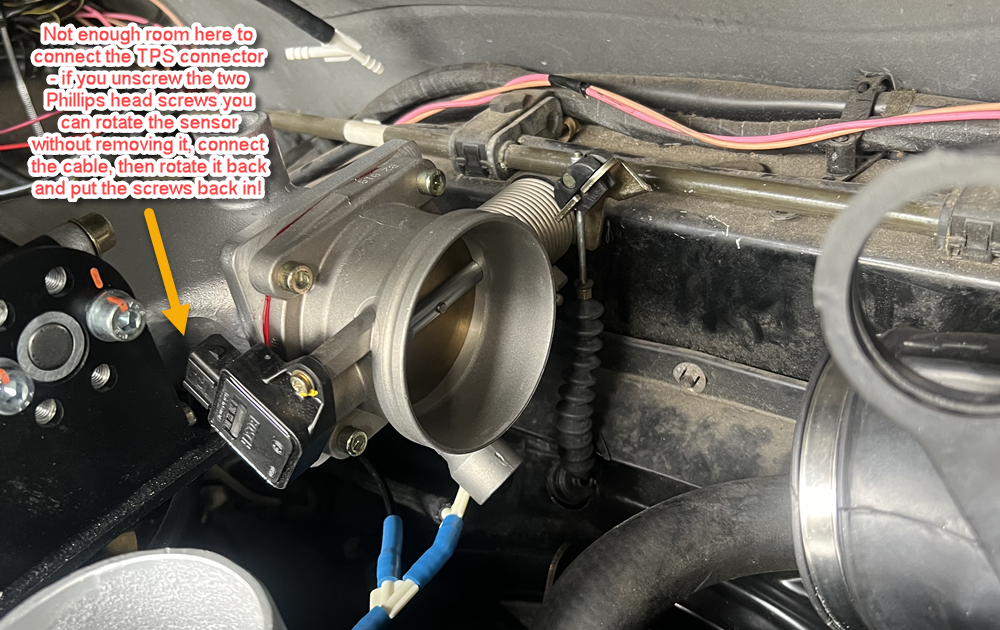
My throttle cable
It looks like the cable is bent, but that's just a trick caused by the wavy rubber cover on it. Similarly, the throttle cable doesn't touch rubber flap around the engine pan, only that rubber cover touches it.
One more annoying thing about the newer kit that you'll notice in Newbian and DocTock's pics above; you cannot access the filler hole on the top of the IC reservoir when the IC is all the way in place! It's hidden under the heat pad at the top of the bay.
You need to loosen the silicone clamps, tip the IC forward, fill the IC, run the pump, fill the IC, run the pump, etc until it's completely bled, then close it up and shift it back into position.
@CosmosMoon Let me know what images you would like from my install that may be of assistance.
That would be great Russ! See my requests below...
Originally Posted by DocTock993
Of significant note: All my engine work was done with the engine dropped and the car on a lift.
That's always easier, but the hardest parts are the crank pulley / serpentine belt - which I did last year when I had my engine out, and getting all the fitting right and the interface between the engine and car that, either has to be done with the engine in, and/or is not that hard to do with the engine in. You need to be able to disassemble the whole intake with the engine in the car for service reasons, so you need to know that you'll be able to get the parts in and out. I suspect they took the SC and IC off when they put the engine back, and then put them back on after - yu'd have to atleast have the IC off to hook up the throttle.
Originally Posted by DocTock993
Of extremely minor note: Your engine pad looks like it needs a "Pad Keeper" from David Etter
Ha ha - yeah, I know! Or a whole new pad!
OK, 3, maybe 4 pics would be good, though I'm not sure how much you'll be able to see with the air filter, blower fan, and IC on there, but let's see...
... EDITED ...
I went back over this whole thread more carefully and realized that the Newbian had posted pics of the latest version of the kit from TPC and that answers a bunch of my questions!
You can see here that TPC does it with the intake all the way to right (not under the SC), and in my test fitting, that does seem to work. You can also see where they've got the ISV - up close and tight by the throttle, and not on the snorkle mount.
You can also see here that they did indeed cut the ring off the snorkle!
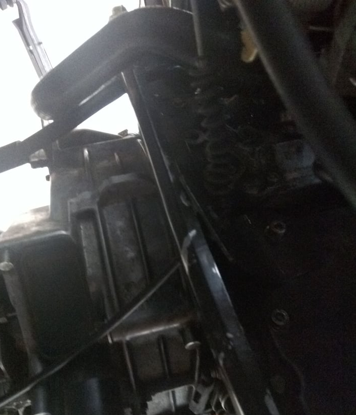
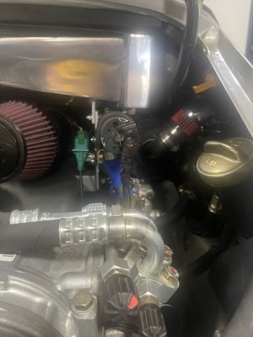
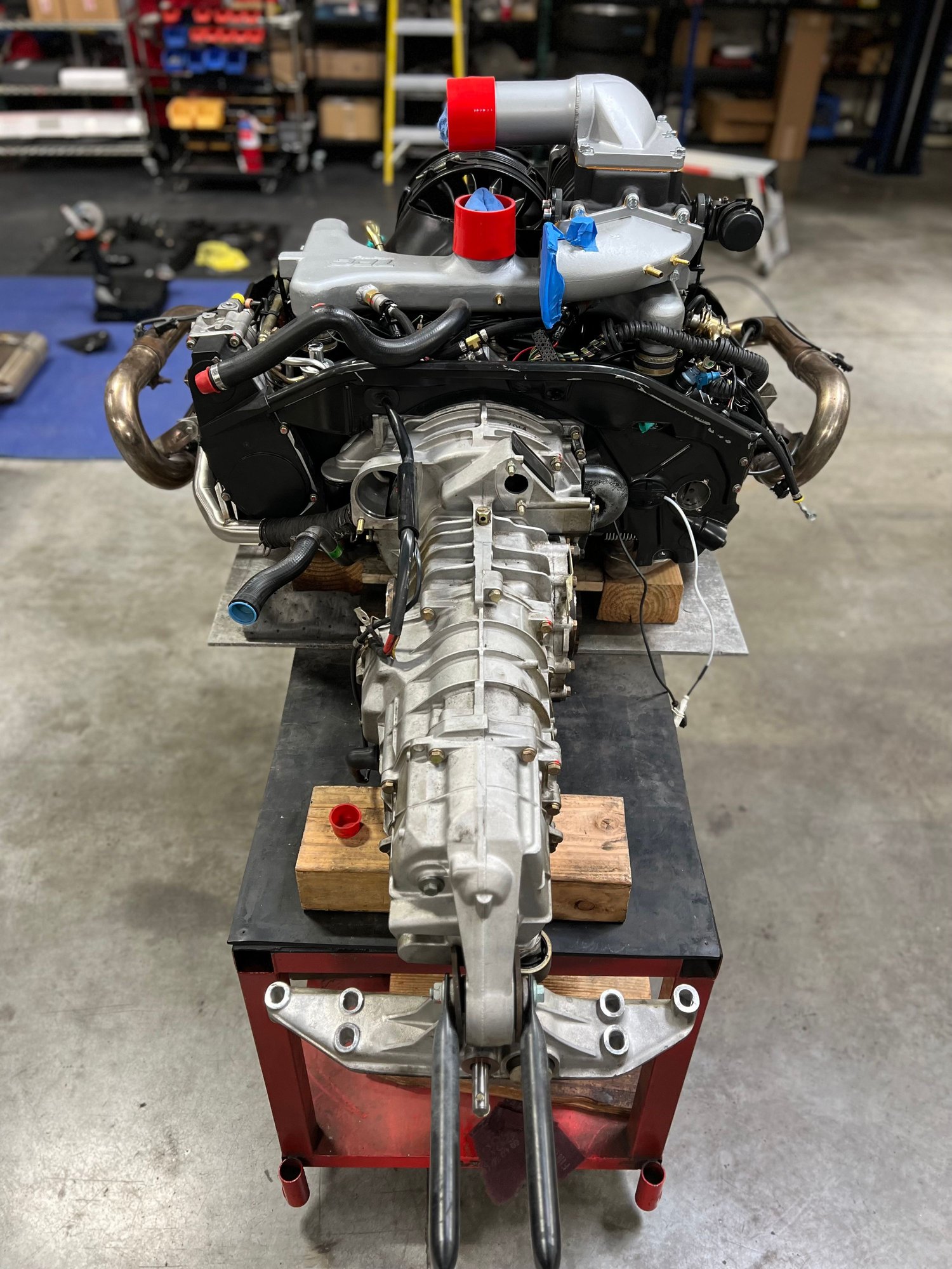
So Russ, what I'd still be curious to see is:
1. Straight down into engine to see the shroud behind the supercharger bracket... like this (I don't have my AC compressor in place obviously, but I think you can get a sense of where the camera is):
2. Whatever info you can get on where the two oil breather hoses on the back right of the engine bay terminate. I suspect (#2) goes to the rubber intake "snorkel," where it bends, and (#1) goes to the small air filter tucked to the right that I see in one of your pics.
Note that in your case the air filter might be connected to the SAI pump (which I don't have, so in that case, I'd DEFINITELY like to know where the two hoses go!
Thanks again, Russ, whatever you can do would be much appreciated! - Chris
Last edited by CosmosMoon; 03-20-2024 at 02:59 PM.
@CosmosMoon
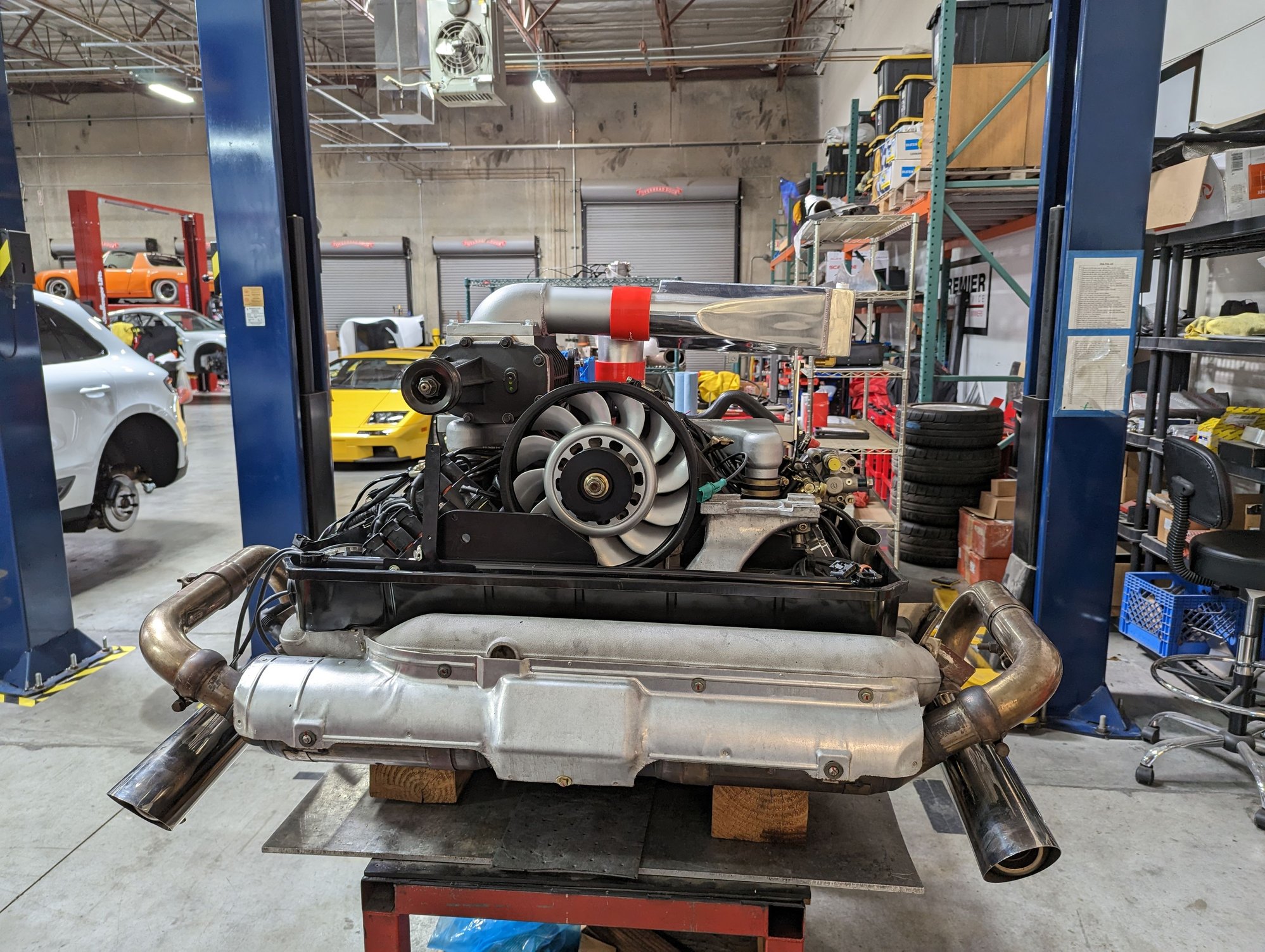
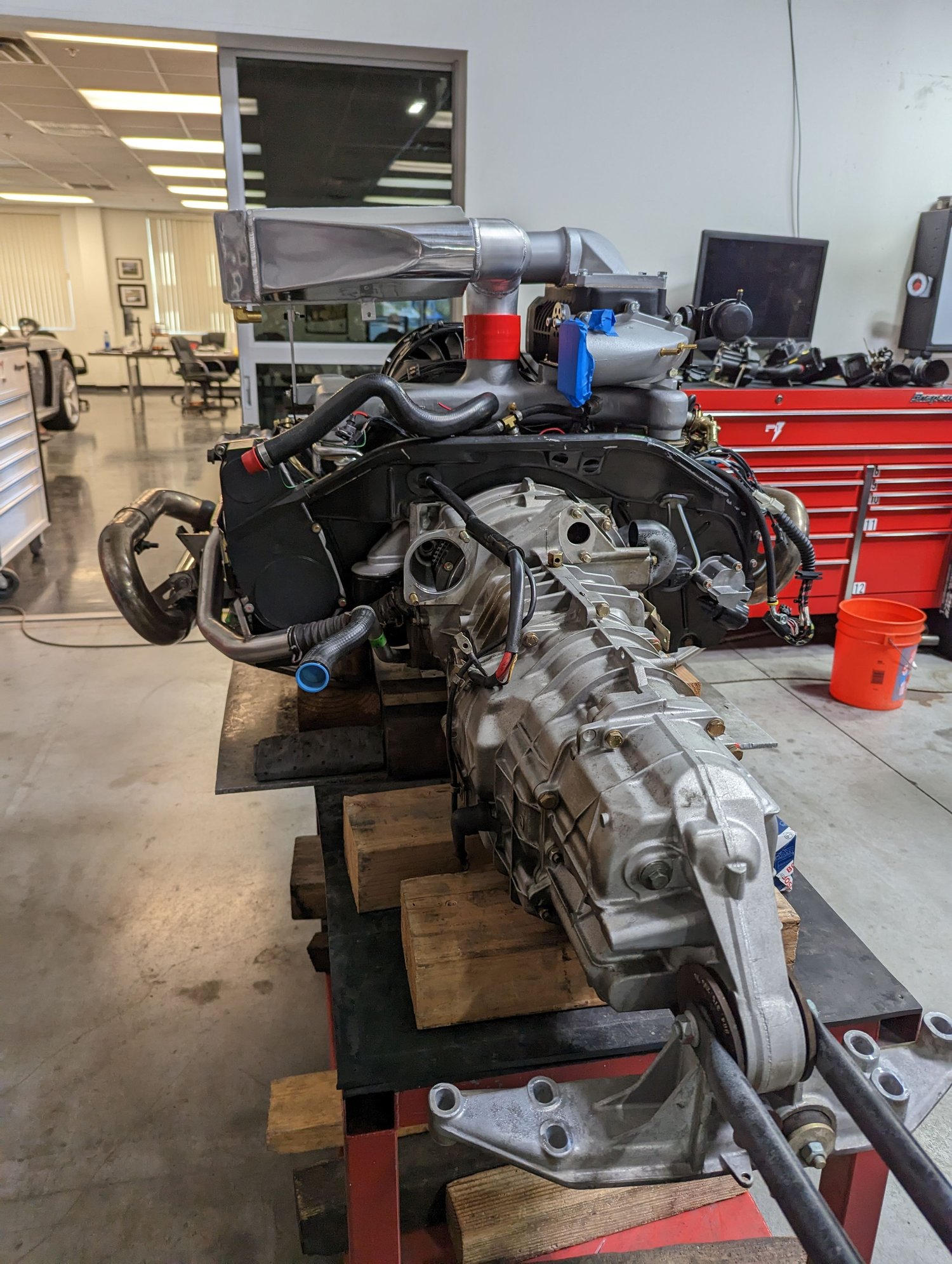
Here are some shots from when installation and engine work was ongoing.
Most have been posted at some point either here on Rennlist or the FB air-cooled group.
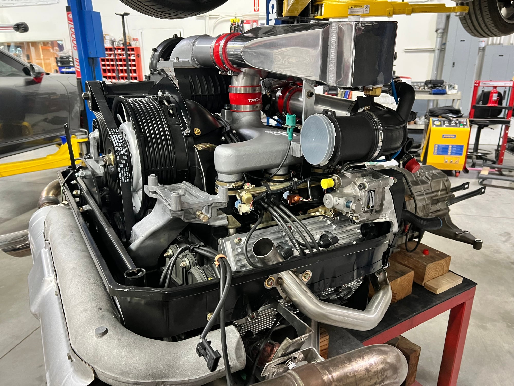
Ok - I can see what's happened. They have pushed the charge-cooler further back into the engine cavity. Thus leaving very little room. So now the ISV needs to be located near the throttle body.
And instead of one long pipe they need to use two short pipes and another connector piece.
And also - you can't extend your large air pipe to the far right because the water pump is in the way - and now the air filter needs to thread under the charge-cooler.
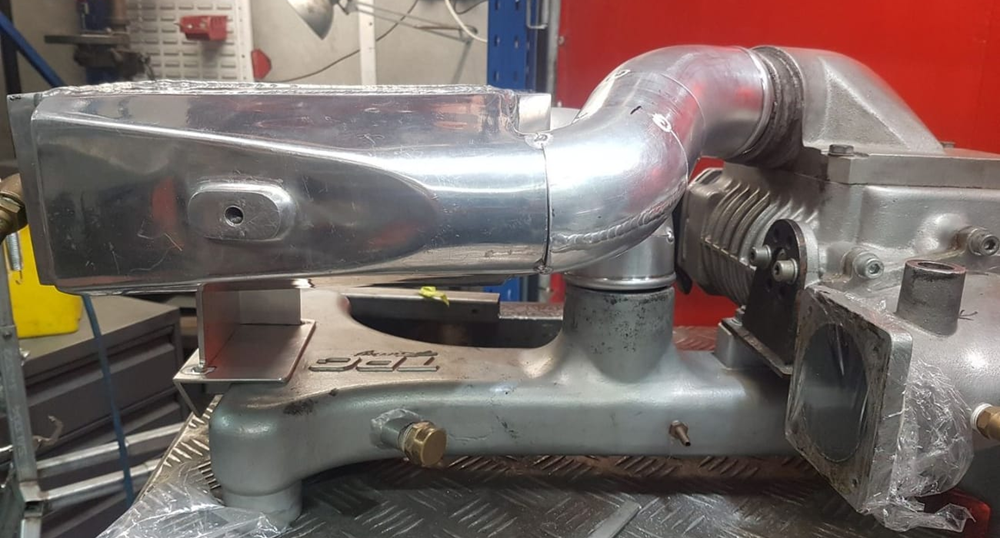
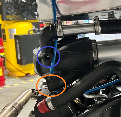
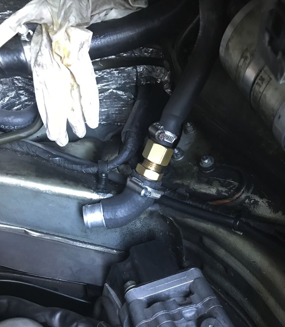
Ok so you can connect the large oil pipe to the orange circle on the intake elbow. You will have to fabricate a custom pipe and use the existing joiner. Large pic below shows the connector I fabricated.
The smaller oil return pipe can go into the blue circle. If not - plug this hole up with a bung - and put a small filter on the end of the pipe. You will need to find the correct sizes to make it join the small air filter.
There will be oil coming out of this pipe (but very little) and you will find that the air filter will slip off easily. So secure it tight or check it from time to time.
Last edited by haygeebaby; 03-21-2024 at 06:48 AM.
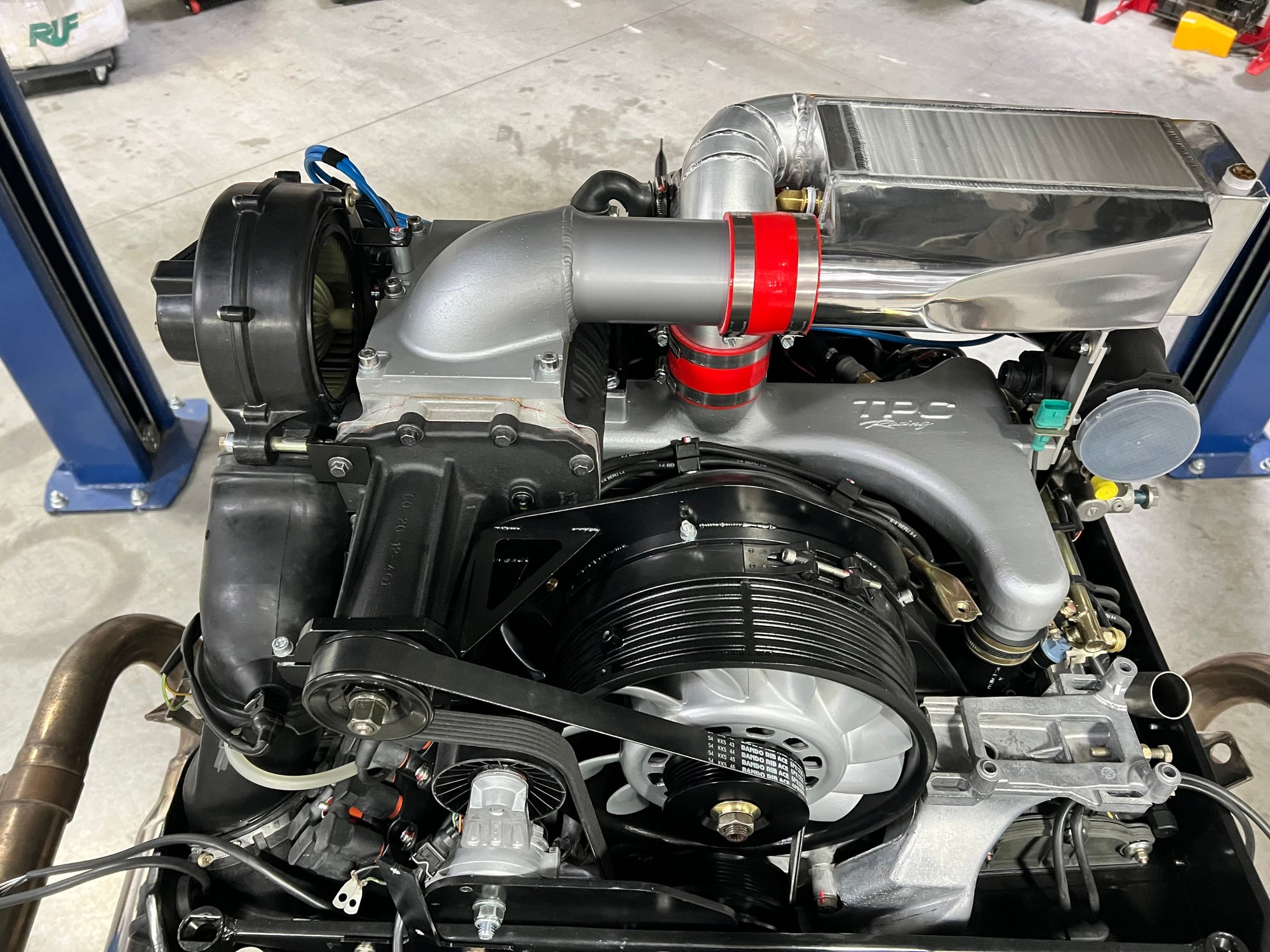
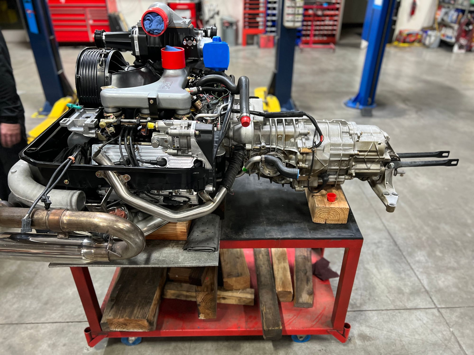
This is my configuration. But using carbon fiber intake pipe to keep the intake air cooler as metal will just keep absorbing heat.
Now is the time to weld in some bungs for sensors if you are planning to do so. I have two on the charge cooler pipe work. One for air coming out of the SC and one for air coming out of the charge cooler.
There was a configuration that I used small air filters on the oil return pipes.
But on the most recent build I plumbed both pipes back into the air intake passage to avoid any vac leaks.
When I did a smoke test to find vac leaks - I noticed smoke coming out of these pipes - so there is some sort of leakage here I think.
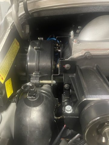
You will notice that I have a custom water reservoir of the left side of the super charger. And I have located the larger Bosch water pump in this area.
I have removed the heater blower motor.
These are older configuration pics - pre Clewitt pulley config.
With Clewitt pulley config the ignition coils stay located in the stock location. Much better than the TPC method which makes it difficult to attached and disconnect the lower coil plug.
And if you use the pulley and belt config recommended by "Windydog" you will have slightly higher boost - around 7.5psi.
With stock TPC you will have under 6psi.
I can't remember the smallest pulley you can use before the Gen4 goes out of its efficiency curve. But when I used it the boost level was very good. Worth changing in my opinion.
I recommend powder coating the charge cooler in black.
I have found it helps with heat. Even if I don't have water being pumped I always see a constant 25 degree Celsius delta with ambient air. Even on hot days.
And the charge cooler is never super hot when I touch it.
If you don't connect back to the carbon canister via the bleeder valve (which has electrical wires going to it) your ECU will pick this up and report an error on the engine error logs.
But this doesn't affect how the SC / engine runs - as I have run my unit connected and not connected.
Last edited by haygeebaby; 03-21-2024 at 07:22 AM.
First off let me say; I love this community - you guys are awesome!
Next up I want to say that this thread has gotten very long with a lot of blind alleys and back-and-forth, but when it's all done I plan on distilling it all down in a definitive manual, something along the lines of; "The Missing TPC Supercharger Installation Guide"!
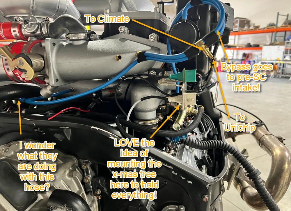
Next up I want to highlight how much conflicting information there is, and how difficult it is to get good answers over the phone. Take, for example, the connection for the SC blower bypass valve. Haygeebaby and TPC (possibly on a phone-call miss-communication) are saying it should be connected on the supercharger outlet side, JuhaG and DocTock993's installer have it connected to the same place as the climate vacuum line - on the SC intake side (which, frankly, makes more sense to me). To be fair, I'm not really sure it matters but it does show that there's a lack of consensus among installers and a lack of clarity in the instructions.
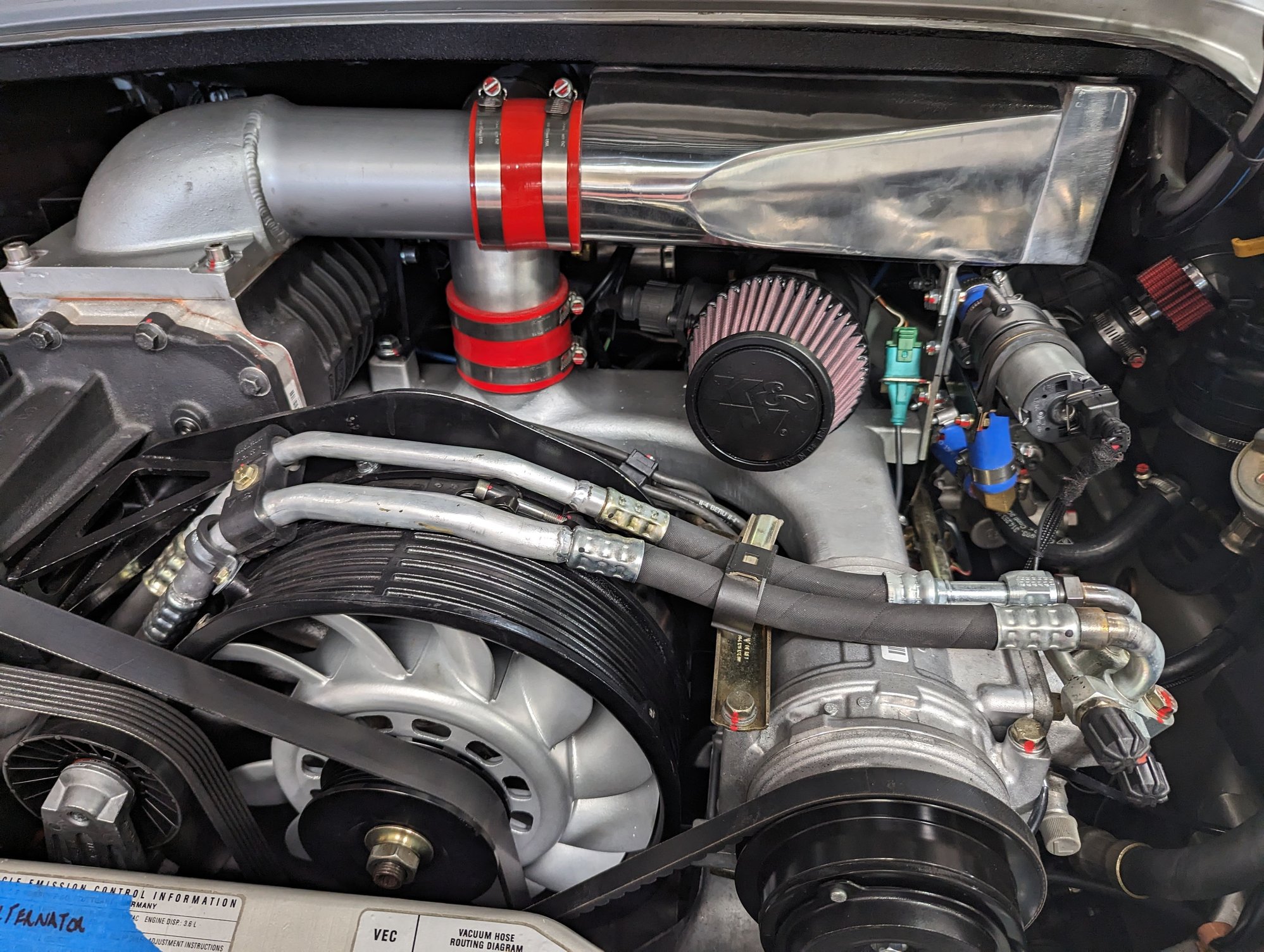
Now let's talk pictures:
Super-helpful! We can see here that:
1. They attached the cover for the opening behind the fan by screwing to the engine cover - which is what I was talking about doing myself, and pretty much the only way it will work
2. I like the way they did the mount for the knock sensor
3. We can see the cut ISV mount from the snorkle
4. This shows why I was saying that doing full the build outside the engine perhaps doesn't work as they later switched from this setup, with the snorkle outside of the bracket for the cooler to one where the snorkle is under the cooler and the intake pipe is shorter
Notes are pretty self-explanatory. The hose leading off to the left, that you see disconnected in several pics has me stumped. It's not needed for anything in any standard setup. Perhaps for some 3rd party sensor?
Also, I'd love to know where they found the squiggly connector hose between the ISV and the intake - it was probably a lot cheaper than the $130 one I got from the 94-95 993 catalog, though it doesn't look as stiff/supportive.
Lovely work over-all!
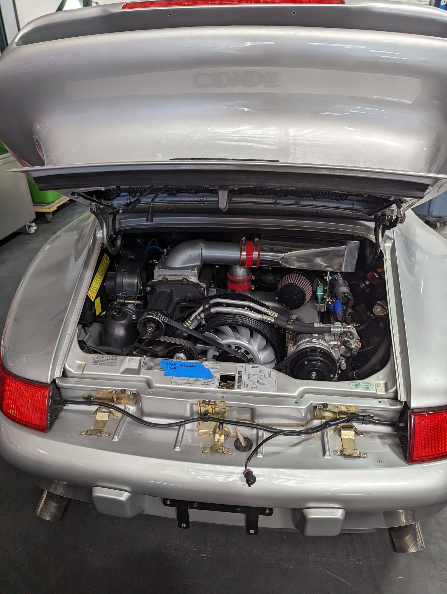
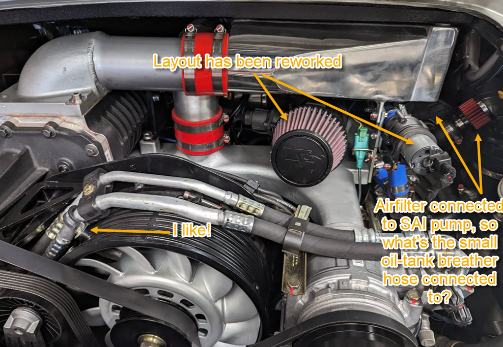
The air filter is definitely connected to the SAI pump and not the ail-tank hoses, so where does the small oil tank hose go?? (agree with Haygeebaby below that the medium sized one goes to the snorkle - it's a natural fit and matches the stock engine)
Here we don't see that extra vacuum hose anywhere, did they abandon it?
Looks just like mine - but I didn't bother removing the oil radiator, and so had a much more difficult time of it - LOL!
I suspect they cut the small metal tube for the ISV here because the tube + red TPC hose is not long enough, and you need the metal tube to go into the both the rubber snorkle and the silicone hose. I'll be using the tube as is and a longer silicone hose and ditching the short TPC hose.
...and there's that orphaned vacuum line again!
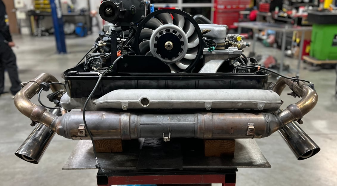
As my 11yo son would say... "Damn! dem pipes bruh!" seriously, your car must sound wicked!
Originally Posted by haygeebaby
Ok so you can connect the large oil pipe to the orange circle on the intake elbow. You will have to fabricate a custom pipe and use the existing joiner. Large pic below shows the connector I fabricated.
The smaller oil return pipe can go into the blue circle. If not - plug this hole up with a bung - and put a small filter on the end of the pipe. You will need to find the correct sizes to make it join the small air filter.
There will be oil coming out of this pipe (but very little) and you will find that the air filter will slip off easily. So secure it tight or check it from time to time.
OK, thanks so much! The larger hose to Orange I pretty much assumed to be the right way - as that's how the stock engines are connected. It's a great way to get oil in your intake if you over-fill at all, which is not cool, but who over-fills their oil right? LOL!
For the smaller one. It comes from TPC with a plug in it, but I noticed in DocTock's pics that the plug is removed, so perhaps they connected it to the smaller tube. The stock engines parts diagram for 94/95 model year shows the plug in that spot, so I assume the stock engine has the hose going to the intake somewhere else (there seems to be a lack of documentation on those car's hose connections and mine is MY '98). The oil-tank to engine bay hose part number is different for pre/post MY 95, but the piece of hose from the plastic coupling to the intake is the same. I have an adapter / reducer in the mail for the air filter (your "plug the hole and use an air-filter explanation), but I'm seriously considering a catch-can as the small pipe, for whatever reason seems to get more over flow than the large one - but maybe that's just because it's under vacuum on the varioram cars.
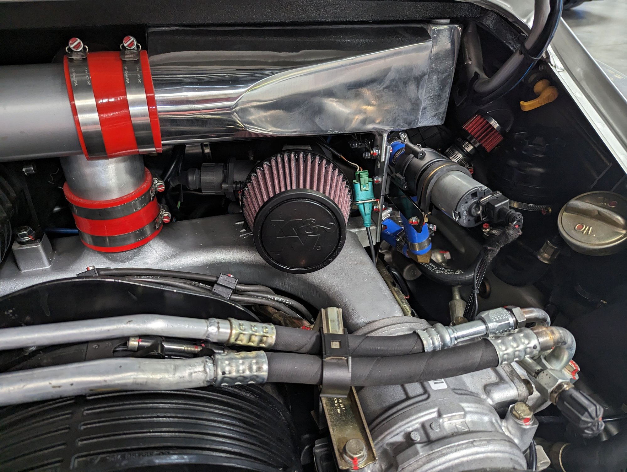
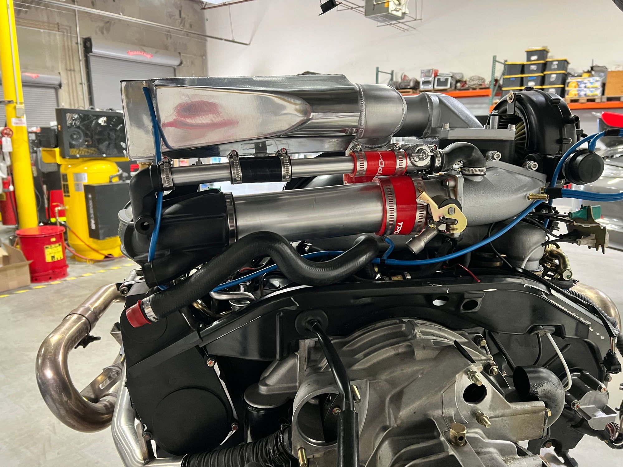
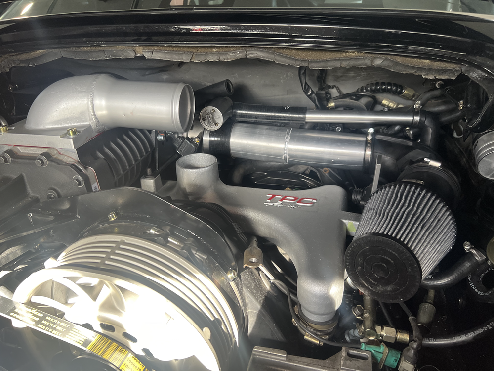
Here you can see my current layout, and the one I'm hoping to stick with. I'm about to finalize and connect everything up - I have already cut down to the special ISV tube.
I'm not sure why some installer chose to put the air intake under the IC and the pump on the outside, and it would require some modding of the pipe exiting the IC and things... but perhaps it's nice to be able to disconnect it w/o getting water all over the top of the engine or something else - we will see as I get to the final steps! (I was actually thinking of putting a coupling in the right front wheel-well where the hose is visible to allow for draining it from there). I want to keep the heater blower, so no room on the left side.
Here's my wire harness for the extra injectors that will connect to the EV-1 connector for the longer of the two unused varioram vacuum lines. The ground side of that connector will be modded to connect to the trigger line from the Unichip (naturally).
I'll respond more to Haygeebaby's last post when I have time later today!
Last edited by CosmosMoon; 03-21-2024 at 08:07 PM.
This is my configuration. But using carbon fiber intake pipe to keep the intake air cooler as metal will just keep absorbing heat.
Now is the time to weld in some bungs for sensors if you are planning to do so. I have two on the charge cooler pipe work. One for air coming out of the SC and one for air coming out of the charge cooler.
There was a configuration that I used small air filters on the oil return pipes.
But on the most recent build I plumbed both pipes back into the air intake passage to avoid any vac leaks.
When I did a smoke test to find vac leaks - I noticed smoke coming out of these pipes - so there is some sort of leakage here I think.
You will notice that I have a custom water reservoir of the left side of the super charger. And I have located the larger Bosch water pump in this area.
I have removed the heater blower motor.
Everything looks super-sweet - lovely work!
Originally Posted by haygeebaby
And if you use the pulley and belt config recommended by "Windydog" you will have slightly higher boost - around 7.5psi.
With stock TPC you will have under 6psi.
I can't remember the smallest pulley you can use before the Gen4 goes out of its efficiency curve. But when I used it the boost level was very good. Worth changing in my opinion.
I used a 2.1" pulley. I got my SC pulley and belt size from a post by Trevor-UK during Meenrod's build https://rennlist.com/forums/993-foru...l#post16299374
... he calculated out a size that would create a similar RPM with the Clewitt setup as the SC sees with the TPC setup.
I can always go bigger later. I think it increased the standard boost by only about 3%
Originally Posted by haygeebaby
I recommend powder coating the charge cooler in black.
I have found it helps with heat. Even if I don't have water being pumped I always see a constant 25 degree Celsius delta with ambient air. Even on hot days.
And the charge cooler is never super hot when I touch it.
Good to know as I was going to do a first, light-throttle-only, test with no water in the system
Originally Posted by haygeebaby
If you don't connect back to the carbon canister via the bleeder valve (which has electrical wires going to it) your ECU will pick this up and report an error on the engine error logs.
But this doesn't affect how the SC / engine runs - as I have run my unit connected and not connected.
I am going to connect the valve and the vacuum to the canister hose.
OK so.... I put it all together and started it up!
Yesterday I went to my friend Todd's house and checked out his car (which has been away getting detailed and cleaned since he's selling it soon). I'd been holding off on check his as I thought he had the older model kit, but it turns out his is the new style. He does NOT have an intercooler, but I was able to see how AutoAssociates did the hoses.
1. The SC bypass is in fact connected to the lower hose barb (SC output) ...along with the FPR and MAP sensor
2. They connected both the small and large oil tank hoses to the rubber intake snorkle. These two hoses are then effectively redundant, since there's no difference between the hose connections or where they go in the oil tank. The only difference is that the small hose has a VERY small opening to pass through in the oil tank (like 1mm hole!) - supposedly as a means of restricting the rate at which the vacuum level in the top of the oil tank can change in the stock engine setup. In the supercharger config however - where both hoses go to the same place and there is no vacuum - they effectively both do the exact same thing. Since I had already found a cute little 90-degree bit of breather hose that was the perfect large / small size to go between the hose and the small K/N filter , I left my small hose just connected to that filter... at least for the time-being.
3. I connected the brake vacuum hose to the carbon canister hose and solenoid - seems to be fine.
4. Squeezing the Intercooler in is brutal. It's so tight against the foam engine bay pad. Outside of that, it's all pretty easy (once you know where to hook the hoses and vacuum lines) I have not yet connected the pump, and have not yet connected the last bit of hose to the pump or intercooler. After I do some more tests and logging with the bypass valve set to max out at around 90% boost, I will tear it down and re-build with the hoses and the water.
5. My first start-up was with the bypass connector on the Unichip - so it was basically running with the stock ECU. Started up and ran well!
6. Next I hooked up the Unichip and Unichip "turbo module" (MAP + injector trigger) again, started up and ran well!
7. Next I tested the injector signal (per the TPC instructions) by using a "noid" light on the extra injector connector and .... it works! Light is off except when first reving the engine - which kicks in the boost and the light goes on.
8. I hooked up my LM-2 and wide-band lambda O2 sensor to keep an eye on the AFR. Seems fine so far. Right at the 14.3 - 14.7 range at idle and dropping when I hit gas.
9. No CEL! (Yet)
10. Next step for tomorrow is to hook the computer up to the LM-2 and go for a gentle drive with logging on � watching the number while driving isn�t practical and they bounce around too much. I�m hoping to sort out how to get the RPM and boost signals going into the LM2 (should be pretty easy) to get a good graph of all three. I also plan on switching to the Unichip software and seeing what that shows for TPS and MAP/boost number in real time and make sure everything is making sense. After that I need to find a local tuner with a dyno and who�s familiar with the Unichip.
Here's a short video of the idle and some goosing of the throttle. Some things to note:
- You can see the bypass valve is working exactly as it should - vacuum is all good!
- the belt is positioned beautifully in the center of the pullies.
- I had forgotten to fully tighten the bolt at the end of the SC nozzle before this video, and I think that's why it's flexing so much
Nice well done.
Check that AFR when you accelerate.
Make sure you are getting enough fuel.
You don't want to grenade your engine.
I'm getting high 11's / low 12's for AFR
Around 14/15 when cruising.
Also - at some point - fabricate a heat shield for the air filter. That area gets super hot.
I'm not sure how efficient the duck tail is at channeling air into the engine bay.
But when my stock spoiler is down - its warm - but when I raise the spoiler and monitor temps - temps go down way faster.
For me - perfect setup would be an RS or CS spoiler - or something fixed that always gets more into the engine bay.
Last edited by haygeebaby; 03-25-2024 at 09:09 AM.
Nice well done.
Check that AFR when you accelerate.
Make sure you are getting enough fuel.
You don't want to grenade your engine.
I'm getting high 11's / low 12's for AFR
Around 14/15 when cruising.
should be able to do road testing this week. I did get the LM-2 connected to the tach and boost signal and the computer in the garage so can start logging.
Originally Posted by haygeebaby
Also - at some point - fabricate a heat shield for the air filter. That area gets super hot.
I'm not sure how efficient the duck tail is at channeling air into the engine bay.
But when my stock spoiler is down - its warm - but when I raise the spoiler and monitor temps - temps go down way faster.
For me - perfect setup would be an RS or CS spoiler - or something fixed that always gets more into the engine bay.
so obviously cooler temps = more horsepower (hence the intercooler) but is there any danger of engine damage from higher temps? I thought the system was sort of self regulating since when the intake temps rise, the air takes up more space and so the SC simply can�t pump any more air in - so the higher the temps, the less air it can add and the so it just sort of stabilizes out.
what temps do you think are too high?
Last edited by CosmosMoon; 03-25-2024 at 07:16 PM.
Sorry Cosmo - I'm probably throwing too much information at you all at once.
I think its best to get the basic kit setup and then enjoy it for a while.
The basic kit does work well. SC whine will put a nice grin on your face.
Look at minor improvements later on.
The climate in Connecticut doesn't look too hot - so you might not need to worry about this.
Run the kit for a while and enjoy it.

 03-16-2024, 05:18 PM