When you click on links to various merchants on this site and make a purchase, this can result in this site earning a commission. Affiliate programs and affiliations include, but are not limited to, the eBay Partner Network.
Sorry Cosmo - I'm probably throwing too much information at you all at once.
I think its best to get the basic kit setup and then enjoy it for a while.
The basic kit does work well. SC whine will put a nice grin on your face.
Look at minor improvements later on.
The climate in Connecticut doesn't look too hot - so you might not need to worry about this.
Run the kit for a while and enjoy it.
ha ha! All good!
yeah, it won't be getting above 15C here for a while, and even in the summer it’s not terribly hot most days.
I took the car out today. My boost signal on the LM-2 seemed a bit wonky so I checked it with a voltmeter and by running the Unichip software w the Unichip connected to the laptop, and it's registering properly, so I must have the LM-2 misconfugured … not a big deal, I’ll sort it out at some point. Doesn't affect the O2 readings. In my little test runs - with relatively low boost and watching the LM-2, I was getting 14.5 ish numbers for cruising going down to 11.2 or so on short accelerations.
Running the car w the Unichip software is really a blast since it shows all the relevant in/out voltages at all times, and when you go to the map grids you see a little red box jump around the grid based on RPM and either TPS or MAP (boost) value. It’s cool to watch and gives a real feeling that everything is working as it should! … but not the best for tuning since it doesn't connect to a wide band sensor for AFR.
so yeah… I'm feeling good, but I am going to find a local tuner who has a dyno and knows Unichip and have them check it with a real exhaust meter for the AFR.
I think it’s time to break it down and tidy up some things, then put it back with the water hoses, pump, and coolant. Thankfully my car is not much fun to drive right now as the interior is a mess with all the carpet stripped out, and it's a bit cold and rainy so I'm not in a hurry!
couple of thing to know about install pics people have posted.
1. there’s only about 4.5” between the intake manifold and the IC. This means that if you want the air filter between the IC and the intake, the air filter that TPC sends with the kit (5” diameter at the base) is going to be difficult or impossible to use. You either need a smaller filter (pretty sure that's what DocTock and Newbians installs have - since the filter is red and not blue) or you need an extension between the filter and the MAF.
2. You cannot use the stock rubber boot that connects the the blower fan to the pipe going down to the heat-exchanges as-is. If you try to, the blower-fan will sit too far back in the engine bay, and the bypass valve on the SC will be in the way. You'd have to be very observant to notice in DocTocks pics that the air sensor on his boot is up by the fan in a weird place - that's because they reversed the boot, and possibly cut it. You have to do this if you want to use the stock blower.
Thanks again everyone!
Last edited by CosmosMoon; 03-27-2024 at 11:05 AM.
OK folks, so I'm going to call this project a success - even though I'm still working out the kinks (pun intended!) of my water hose routing and so have yet to fill it with water.
I got the boost signal figured out on the LM-2 - each analog input has a ground wire that has to be grounded - the RPM input also has a ground wire, and that does NOT need to be grounded. Once I grounded the (-) wire for Analog In #1 - it worked great. Map voltage is about 0.8v or so and goes up to 2.8v on heavy boost.
I then drove around with the laptop hooked up the LM-2 and did some datalogging, and the charts look exactly as I would expect - boost and AFR are almost a perfect inverse relationship on the charts. Logs are on the laptop - I'll try to post some screenshots. I think it'd be helpful for accuracy when reading the charts to dial back the display range for the AFR as it's currently set up for like 7 - 20 for the chart scale. According to the display I'm getting the numbers I mentioned above - 14.7 - 15 at idle, and 11.2 or so on WoT. Side note; when you go off-throttle with the car in gear, the engine goes "full lean" as it's basically running on vacuum with no fuel - and the AFR numbers go up to like 20 - 60 ... I bit unnerving, but this apparently totally normal.
I haven't had a chance to do a good long pull yet, and chart it - that will be this week, but I'm feeling really good about the numbers I'm seeing and the way the car is driving now that the ECU has gotten past it's "learning phase". The sound of the lightweight flywheel is a bit aggravating since I have the whole center console out and all the carpets ripped out (I'm replacing them) and the little rubber plug pulled from over the transmission to run the LM-2 sensor cable back to the exhaust - that flywheel can-of-BBs sound is really loud. ...and naturally I'm listening carefully for any odd sounds while driving, so it's extra annoying. I have a funny feeling that with all the extra torque I've got now I will be going back to the stock dual-mass flywheel next winter - LOL! I think that the ease of pulling the SC will make the whole engine-drop process that much easier - might be able to do it w/o pulling the bumper.
I was quite annoyed by the TPS connection and how you can't connect it w/o unscrewing the sensor, so I made a pigtail for it with a male/female pair of 3-pin EV-1 connectors
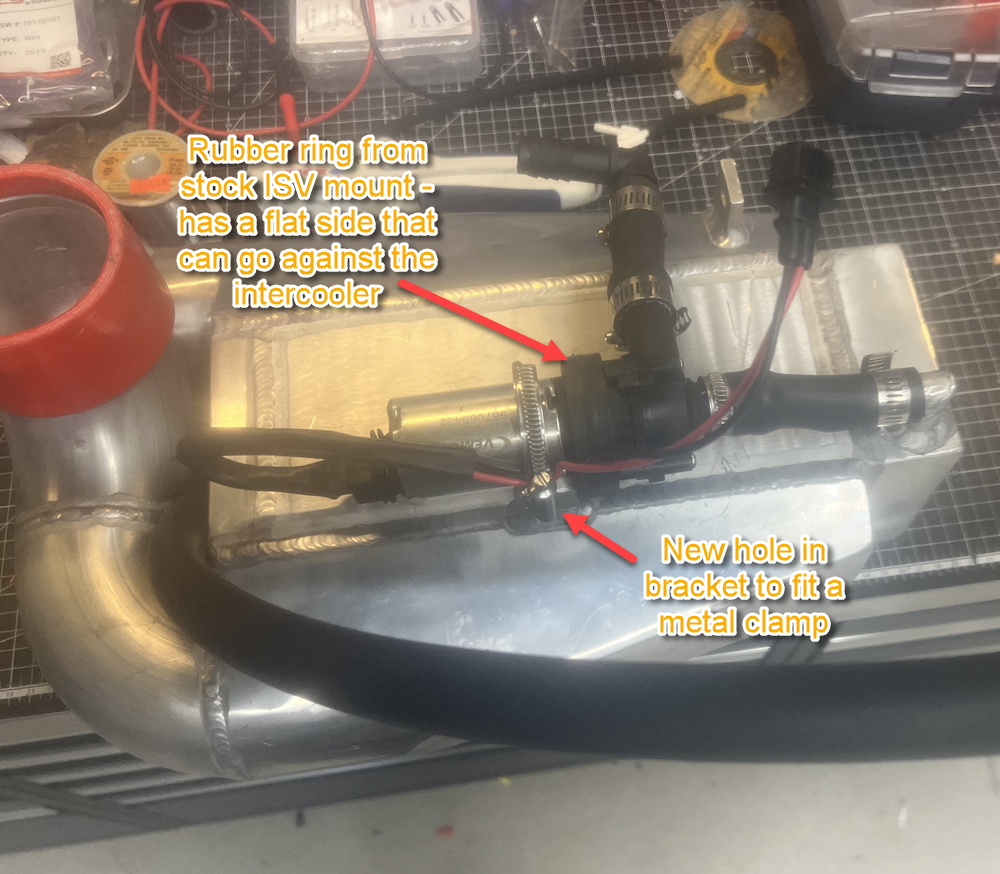
Here's my pump + intercooler setup (sorry for the image quality. WIth a metal clamp holding the pump on, and the flat-sided rubber ring from the ISV fitting perfectly around the pump-body, the pump is locked in rock-solid, no movement what so ever.
Note angle of the pump and the 90-degree connector on it - this hose connection worked out perfectly.
The last thing I need to sort out is the other hose connection... you can see it in DocTock's pic here, and if you think about where it's point, it's pointing straight into the big intake pipe and the smaller ISV pipe
So my original plan of just running that hose straight to the intercooler from near the back of the engine bay doesn't work, those tubes get in the way too much .
It seems like I need a 90degree bend to turn it toward the left side of the engine bay - then the hose will be run probably under the ISV (that will have to be tipped up a bit) ... I can't really think of a better way to do it. I have some quick-disconnects coming from McMaster-Carr in the next day or two and I will sort out the details for that last bit after they arrive, and then I will put the water in, and then I will be done!
Driving the car has been super fun, and it's definitely noticeable. Hopefully I can take it to a tuner with a dyno by the end of the week, I'd like to get some real numbers and have a pro vet the AFRs as I think they may be a bit rich. It's no real rush though - for the kind of driving I'm doing, just tooling around and not tracking it or really even pushing it any where near the limit - I feel it's all safe. I'll post a few more final pics when it's done.
Nice work - thanks for sharing your journey with us.
For the plug to the TPS - I can plug mine on and off without much trouble.
It just has to go on an angle.
What boost numbers are you getting right now with the pulley setup you have?
Nice work - thanks for sharing your journey with us.
For the plug to the TPS - I can plug mine on and off without much trouble.
It just has to go on an angle.
I think this is a failing of the new design - the fit is just too tight. The larger end-bit of the connector just can't make it past the black aluminum mounting plate for the SC. I tried it on the bench quite a bit, but I'll try again next time I take the SC off.
Originally Posted by haygeebaby
What boost numbers are you getting right now with the pulley setup you have?
It's hard to say exactly since I haven't been able to find a chart or formula for the MAP sensor to translate voltage to PSI (or bar). I'm at sea-level, and when it starts up the voltage is about 0.85 - 1v. Since the signal goes up to 5v, and since I think it's a 2.5bar sensor, I would think that means that 0 - 1.5bar of boost is from 1 - 5v on the output. That would mean that
boost (in bar) = ((v - 1) / 4) * 1.5 = (v-1) * 0.375
v = voltage from the MAP sensor
though you can't be sure of the scaling, or what the max voltage is.
The max voltage I've seen when logging is about 2.7v, which - if my theory is correct, would translate to 1.7*0.375 = 0.637bar of boost ... which is over 9 PSI and that seems too high to me based on what I've seen from others and the fact that my boost should be lower than the max, and because I'm not pushing it very hard. It's also the case that the mapping table in Unichip measures the boost signal from min to max of 0.43 (min) to 4.35v (max) ... so who knows? My understanding is that the max reasonable boost from an M90 is about 12PSI?
- I'd love it if anyone had more solid info on this, but, it's really just a numbers game - I feel the power / torque, and it's cool
I'm curious to see what it's like with the intercooler running - I hadn't realized just how hot the intake gas gets under high boost - the pipes are definitely hot after a drive.
Last edited by CosmosMoon; 04-02-2024 at 10:03 PM.
One more thing to add, for those who installed the TPC kit on a varioram engine, I assume you get Durametric fault codes 175 & 209 due to the disconnected wires to the vram actuators? I just hooked up my UDT999 and ran a scan and saw them. Can�t really think of how to avoid it unless perhaps putting a resistor across the terminals in the unused connectors.(no CEL, just the fault codes - they are definitely due to the disconnected vram)
I�m happy to report those were the only faults I had - no knock sensor fault!
I have an early TPC Supercharger, no inter-cooler for many years now. I had TPC do a final tune adjustment shortly after the install by Euroquip near Chicago. They did a very clean install. Where TPC instructions say to use tie wraps where my shop made metal brackets. I suggest replacing the plastic tie wraps as they deteriorate over time and break. My car has many thousands of miles since the install, it runs great, best bang for the bucks...
I have an early TPC Supercharger, no inter-cooler for many years now. I had TPC do a final tune adjustment shortly after the install by Euroquip near Chicago. They did a very clean install. Where TPC instructions say to use tie wraps where my shop made metal brackets. I suggest replacing the plastic tie wraps as they deteriorate over time and break. My car has many thousands of miles since the install, it runs great, best bang for the bucks...
Good Luck to you...
Hey Bock, Yeah, I was thinking I may head down to TPC and have them tune it (especially since I have good friends to visit in both south Jersey and the DC area).
As for the plastic ties, I only used them to hold the water hoses for the intercooler in place, and even for that, for the spots that were harder to reach, I used some super industrial ones from McMaster-Carr that are like a 1/2" wide!
For stuff like the water pump mounting, larger vacuum lines, and breather hoses I used metal clamps. Outside of that, I haven't run into any place where I've needed either tie wraps or custom brackets. The only custom metal bracket I can foresee myself needing is one for the heater blower motor - that will be the last thing I'll be hooking up since I doubt I'll need it until the fall.
Thanks for the encouragement. Even with it running at not-full boost and with no water in the intercooler it's already such a noticeable difference just driving around town - I'm very happy with it.
The installer I used for my TPC was adamantly opposed to the "Zip tie" or metal clamp method of dealing with all the moved parts.
His point was it would all have to be UN-done to do ANY work on the car in the future including something as "simple" as an oil change.
Yes it was more expensive to get custom brackets created at time of install, but now the car can be serviced by almost any air-cooled shop.
I agree with your installer on the brackets *IF* you had to remove the water pump from the intercooler to take it out.
See my pics above... my intercooler with the pump clamped to it go in and out as one complete unit when the pump is mounted below the intercooler, and it's rock-solid - literally like one block of metal. I don't ever plan on separating them again unless I start going down the slippery slope of trying to maximize water flow and get a new pump, and I will probably try to mount that pump the same way! I've done a lot of watercooling of PCs and this is all similar but on a larger scale. It's like having a reservoir, radiator, and pump all in one unit.
I've taken the IC + pump in and out that way about 4 times already and it's no more difficult than taking out the intercooler w/o the pump. I can have the intercooler and the supercharger out of the car in probably 10 minutes. Not exaggerating - I've done it so many times! Putting it back takes a bit more finagling only because that intercooler is such a tight fit, and you have to make sure you've got everything connected and routed properly, and then I'd have to fill the water up again (see below).
Don't get me wrong, your installers did a beautiful job, and everything looks very pro. I'm just saying that some setups need more customization than others. I also agree that ease of maintenance should be a high priority. You'll notice on mine that there's an extra connector on the hose coming off the water pump - that's only there because the 90-degree elbows I used had multiple barbs and are a real hassle to pull the hose off of, so I added an an extra single-barb connector that's easy to separate - just to make it easy to get the hose apart! I'm probably going to replace that whole section with something else - like a sweeping-bend aluminum tube or something.
...note also that even with the water to deal with, taking the SC and IC off is still easier than trying to get the varioram intake off - which is a big PITA - so from a maintenance perspective, I think the TPC-equipped cars are easier to work on than varioram cars, and if you have a TPC kit with no intercooler (or an air-to-air intercooler), it's massively easier to deal with.
Anyway... I finally got my water hoses routed properly, the intercooler filled, and the air burped out. It's all done and all good. Intercooler was a little warm after a "spirited" drive today, but nothing like the too-hot-to-touch temps that I had over the weekend with no water in the IC. While doing this hose-routing work, it occurred to me that the reason why the installer for you and Newbian routed the air filter under the intercooler, instead of outside of it is because you have the SAI pump in the back right corner of the engine bay, and it would be in the way of the big intake tube if you ran the tube all the way to the right side of the engine bay. Since I don't have an SAI pump, I was able to put the tube out to the far right side, and the water pump under the intercooler and still have a bunch of room under the intercooler to work.

 03-26-2024, 06:27 PM