When you click on links to various merchants on this site and make a purchase, this can result in this site earning a commission. Affiliate programs and affiliations include, but are not limited to, the eBay Partner Network.
Anyone with shop manual? Need help “electrical issue” headlamp bridge wiring
Working through an electrical gremlin/s of late. Perhaps I should say another.
My car sat for awhile so suddenly alarm, key ignition immobilizer well now she runs. Right side headlight would not come on. I know zero about electricity.
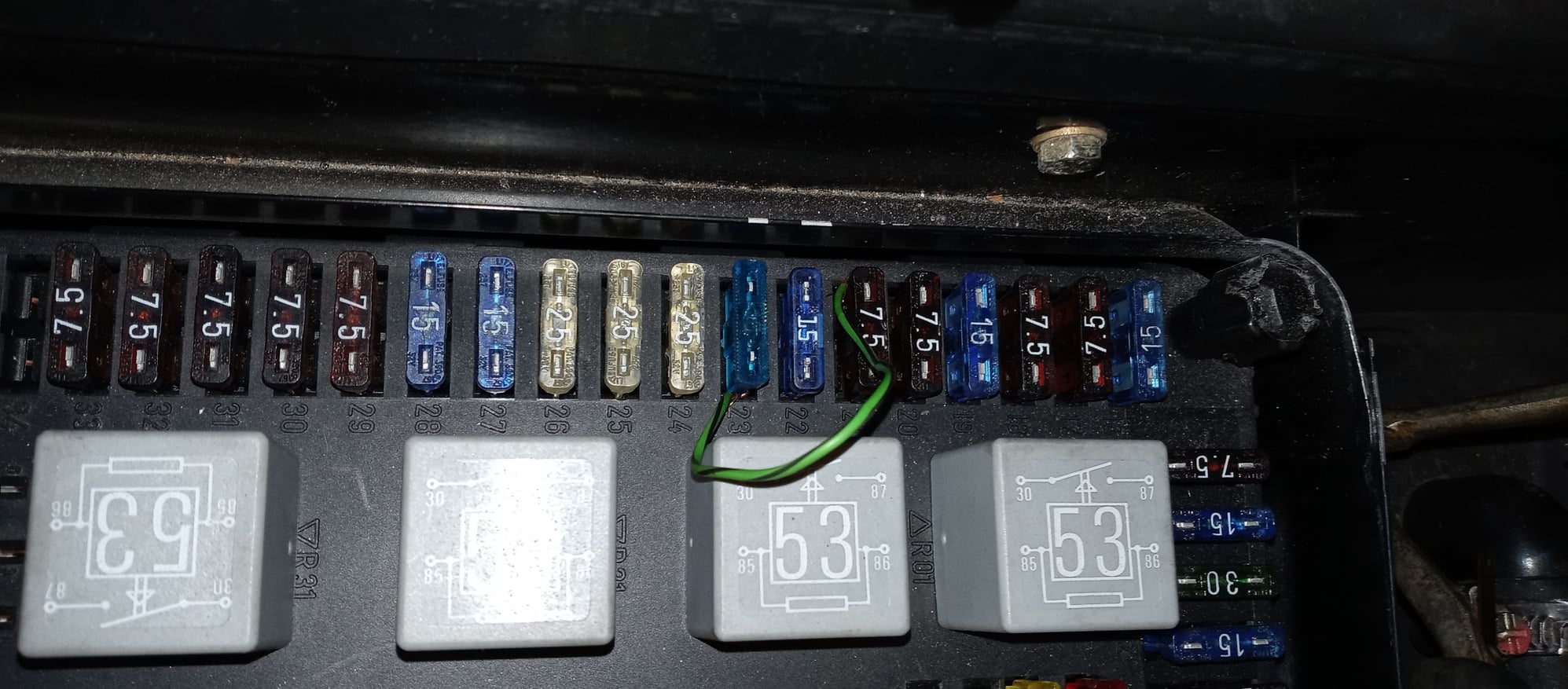
Resolved temporarily by having a friend create a link/bridge by drawing power from Fuse 21 to fuse 23 to power up passenger headlamp atleast for now.
Not one fuse was blown? But 15 amp fuse 23 has no power.
The problem or solution to the problem appears to point to the "bridge."
As per drawing attached.
Copy of linked fuses / bridge attached
NEED a copy of shop manual or portion of “electrical drawing” to do some tracing
Can anyone assist here?
Thanks in advance for your time, TJ Bridged fuse 23 to fuse 21 Headlamp wiring. Fuses tie to bridge
Out of curiosity, where did the above image come from? I ask because the bridge connection seems incomplete.
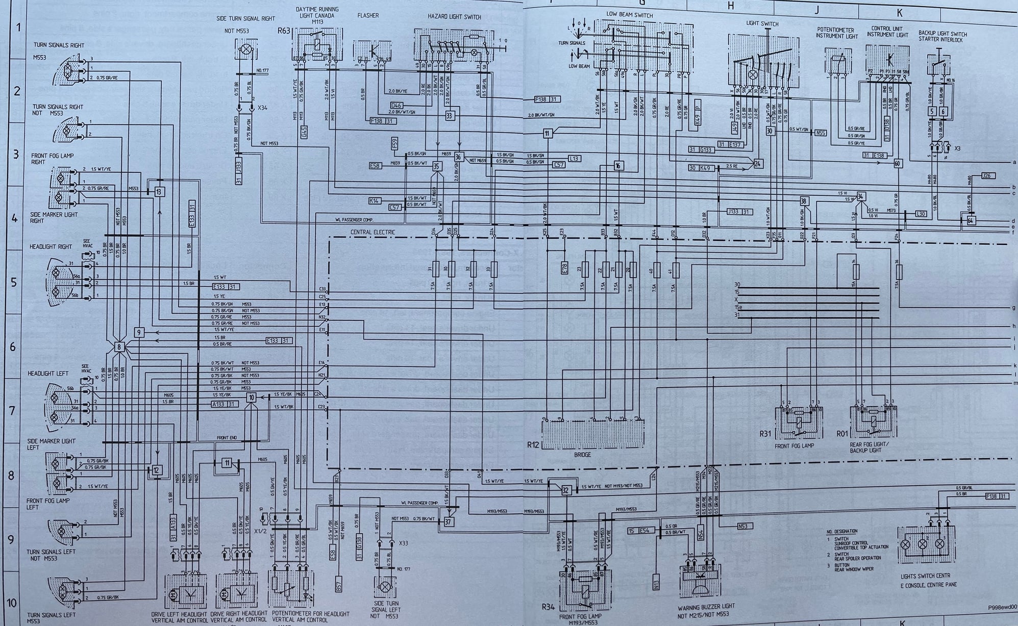
Unfortunately the copies of the factory manual floating around have very poor scans. I also have a copy of the Bentley manual which contains the actual factory diagrams in much better quality. I scanned and combined the two pages you're looking for (see below) so it's easier to follow. See "R12 Bridge" right in the middle. Just above that are the fuses you refer to.
The bridge is the connector on the back side of the fuse panel. There are approximately 10-12 large connectors with various wires that attach to the back of the panel. These connectors span multiple fuses which plug into the front side of the panel. The wire colors are designated and these are the ones that feed into the connector on the back, so I'm not sure you'll get anything more out of this inquiry other than having a copy of the factory diagram. BTW, on the factory version, you need to trace back the lines a bit further to see which wire colors correspond to which pins on the bridge (connector).
Last edited by boomboomthump; 12-05-2021 at 09:51 AM.
Here's the full Wiring Diagram volume from the factory manual. As you can see, most images are blurry. At first glance they seem OK but many of the very small print such as the wiring colors are completely illegible.
The pictures I took and posted above are much better quality.
[QUOTE=boomboomthump;17825428]Out of curiosity, where did the above image come from? I ask because the bridge connection seems incomplete.
Unfortunately the copies of the factory manual floating around have very poor scans. I also have a copy of the Bentley manual which contains the actual factory diagrams in much better quality. I scanned and combined the two pages you're looking for (see below) so it's easier to follow. See "R12 Bridge" right in the middle. Just above that are the fuses you refer to.
The bridge is the connector on the back side of the fuse panel. There are approximately 10-12 large connectors with various wires that attach to the back of the panel. These connectors span multiple fuses which plug into the front side of the panel. The wire colors are designated and these are the ones that feed into the connector on the back, so I'm not sure you'll get anything more out of this inquiry other than having a copy of the factory diagram. BTW, on the factory version, you need to trace back the lines a bit further to see which wire colors correspond to which pins on the bridge (connector).
[/Quote
Thanks to IXLR8 i need a 97 or 98 drawing as my. Car is 11/96 build being a 1997 Carrera.
The drawing is from a parts rep at a dealer.
Cant say sho cuz sharing state secrets is a no-no!
TJ
Out of curiosity, where did the above image come from? I ask because the bridge connection seems incomplete.
Unfortunately the copies of the factory manual floating around have very poor scans. I also have a copy of the Bentley manual which contains the actual factory diagrams in much better quality. I scanned and combined the two pages you're looking for (see below) so it's easier to follow. See "R12 Bridge" right in the middle. Just above that are the fuses you refer to.
The bridge is the connector on the back side of the fuse panel. There are approximately 10-12 large connectors with various wires that attach to the back of the panel. These connectors span multiple fuses which plug into the front side of the panel. The wire colors are designated and these are the ones that feed into the connector on the back, so I'm not sure you'll get anything more out of this inquiry other than having a copy of the factory diagram. BTW, on the factory version, you need to trace back the lines a bit further to see which wire colors correspond to which pins on the bridge (connector).
Awesome! Thank You!
Lets see who can print this?
Thanks TJ
ps..Can not say porsche employees name who "made honest mistake" actually trying to help a 11 year Porsche customer! Said actions are verboden!
Last edited by TJ993; 12-05-2021 at 05:29 PM.
Reason: Addl info
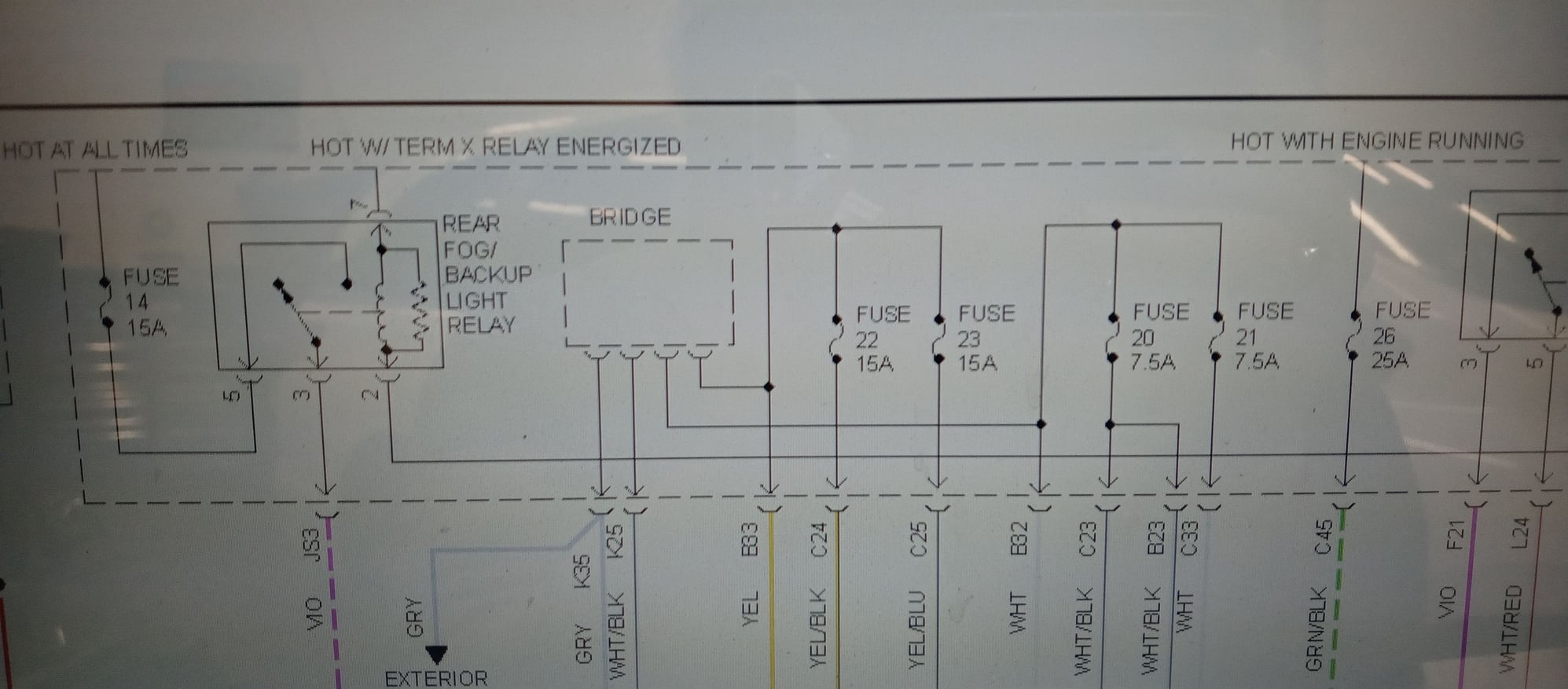
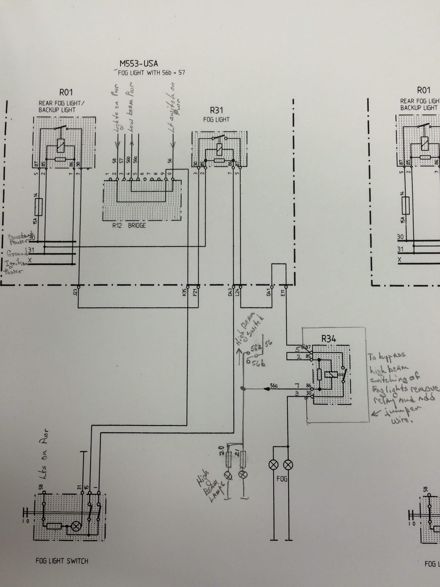
I sold my car and the manuals with it. But here is a markup of the foglights circuit I did a few years ago to help someone else. It has some detail of the R12 Bridge.
The bridge is literally a bridge. The circuit is designed to cut power to the fog lights when high beams are on, that’s it. It looks like a short relay and is slightly different depending if you have a Canadian market model with daytime driving lights, etc.
That’s not your problem Simply, your right side low beam filament is dead. What you have done is bridged the high and low beam circuits. So the right side high beam is lit, and the left side high and low are lit. This is putting double the amps through the left side circuit from what it’s designed.
Pull the jumper before something melts and replace your right side headlight bulb.
I hey Nick
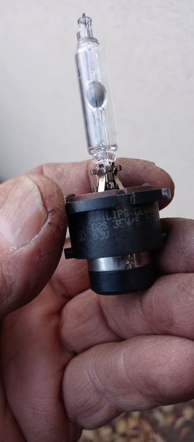
i pulled the bulb.Looked fine except...hav a look. Black spot? Whats this?
Easy approach find another bulb and see what happens next.
Wonder why fuse has no power?
Thanks TJ Is the black cancerous?
Last edited by TJ993; 12-07-2021 at 01:40 PM.
Reason: Pic
Thank You. I have to get my head into this and all of the drawings I received shpould help me find a fix.
I am not used to the headlight bulbs - Osram D2S or Philips 85123.
I posted a Pic - appears normal - no obvious issue to me except the black circular spot? for lack of better word on the bulb >Pic posted
Any thoughts here? Suggestions
Thanks!!
TJ
A black/burnt spot is typically a good indicator of a burnt filament. Stick the left side bulb in and see if it works, if yes, then you've found the problem
Here's the full Wiring Diagram volume from the factory manual. As you can see, most images are blurry. At first glance they seem OK but many of the very small print such as the wiring colors are completely illegible.
The pictures I took and posted above are much better quality.
ELECTRICAL MANUAL VS PICS - PICS FAR SUPERIOR. THANK YOU!!
Just noted a prior thread wherein you posted this: Litronic HID issues???
post # 4: High beam, low beam, or both? If it is both the problem is likely at the ground point VI on the central electric panel (diagram says member right side).
If it is only one of the bulbs out check for power at the respective fuse (when the light is out), 21 for right high beam or 23 for right low beam. No Power
If the light is out and you have power at the fuse then there is probably a bad connection at the headlights or the headlight ground.
If there is no power at the fuse the problem is on the dimmer switch side. If the power or ground to the high beams is intermittent it will be engaging and disengaging the fog light relay R34. That is probably what you heard. That's not likely to be the cause of the problem." https://rennlist.com/forums/993-foru...id-issues.html
OK so I believe u said u sold the car OK But I will try your 2016 fix recomendation
"If it is only one of the bulbs out FUSE 23 for right low beam. No Power> CORRECT
If there is no power at the fuse the problem is on the dimmer switch side."
OBVIOUSLY TIME TO double check I switched BULBS, CANT REMEMBER if I did, they are such a Pain to remove and re-assemble.
I definitely swopped ballasts, bought 2 more recently no luck there!
Interesting thread by NC TRACKRAT - "Odd Running Lights Problem and Solution" what a coincidence, IS IT? https://rennlist.com/forums/993-foru...-solution.html
cars are how old? SWITCH OXIDIZED?
Maybe its time to remove some switches? Electrical contact cleaner or an eraser sand paper?
Whats the fix - time to do some more reading! Thanks again
TJ
Last edited by TJ993; 12-08-2021 at 05:31 PM.
Reason: TYPO I cant type
The bridge is literally a bridge. The circuit is designed to cut power to the fog lights when high beams are on, that’s it. It looks like a short relay and is slightly different depending if you have a Canadian market model with daytime driving lights, etc.
That’s not your problem Simply, your right side low beam filament is dead. What you have done is bridged the high and low beam circuits. So the right side high beam is lit, and the left side high and low are lit. This is putting double the amps through the left side circuit from what it’s designed.
Pull the jumper before something melts and replace your right side headlight bulb.
Hi Nick
I removed the jumper. Installed new bulb Osram D2s 66240CLC in Passenger headlamp = no joy.
I thought I had a good connection when I re-installed headlamp?
NO PASSENGER LIGHT YET
I bought2 new to me ballasts. Then swopped ballasts new and rt side with no luck. A question - can any ballast work?
There is a 2.0 and 2.1 - assuming I have 2.1 in the car.
Bought older pair, installed passenger Side AND NO JOY
Goin 2 remove inner fender now to verify there is a good connection.
After this if no luck will swop Igniters side to side.
After this no idea. The Multi-Switch with signals and headlight hi low & cruise etc is broken? Replace this and..
Thanks TJ New Osram 66240CLC - classic
Last edited by TJ993; 12-14-2021 at 12:46 PM.
Reason: typo
Update - yes Nick is correct, the new bulb did not connect. The issue was a burnt bulb.
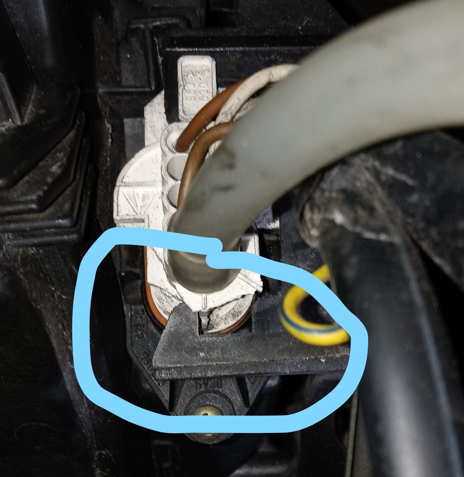
The problem now is the connection - the old plastic end has broken off.
I took the inner wheel well out to discover there was no connection. Thank You everyone for replying!!!
Thanks Nick for nailing it!! Perhaps you are in the biz?
Now I need to replace Part # 999-650-150-40
Glad to hear! No magic, I've just spend a lot of time with the wiring diagrams. The old, "even a blind squirrel..."
I'm not sure about that particular connector, but likely you'll need a round electrical pin extraction tool. They come in all different diameters. I would avoid the cheap 39-piece or whatever sets on amazon- those don't fit anything very well. I can't confirm, but this Lisle key should have one that fits, and it's decent enough quality- https://www.lislecorp.com/specialty-tools/terminal-tool

 12-04-2021, 04:36 PM


 Simply, your right side low beam filament is dead. What you have done is bridged the high and low beam circuits. So the right side high beam is lit, and the left side high and low are lit. This is putting double the amps through the left side circuit from what it’s designed.