DIY Engine Rebuild - Part X (10) - Piston's a pumping....
 03-21-2006, 02:05 AM
#1
Addict
Lifetime Rennlist
Member
Lifetime Rennlist
Member
Thread Starter
Hello All,
Sorry for the big time gap, things have been moving slow and I just got back from spring break in Maui (yeah, someone has to do it).
This episode covers assemblying the pistons/cylinders, heads and cam towers...lots of work and prone to errors.
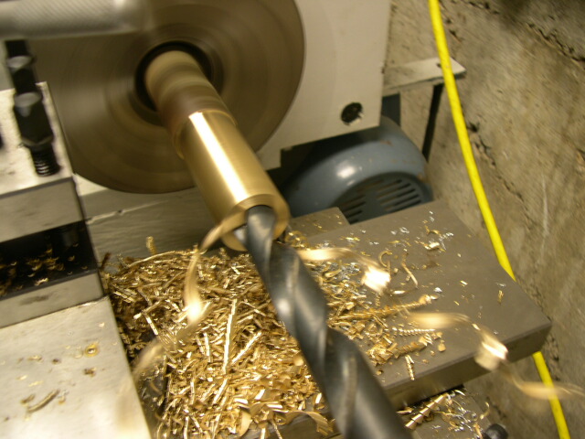
First of all I had to machine a tool to insert the wrist pin clips. They are really stiff and hard to do without the tool...so I fired up the lathe to machine the tool. Of course this means I had to INSTALL and WIRE the lathe since it was not running yet, and then get the right cutting tools, and then machine the piece out. Worked out great in the end though...and the tool works slick. Unfortunately I don't have a lot of shots of it and I have lent it out to another 911 engine DIY'er in town.
Here is a barrel ready for its piston...I liked this shot because of the neat gleam on the surface of the barrel.
The rings come in seperately wrapped packages. I found the most difficult ring to be the oil ring...its fragile and you have to keep the inner spring inside properly. I installed and removed the rings a few times to both get the feel and to see than nothing breaks....all seemed to be OK. The top and second rings (compression) have an orientation that you have to watch for.
Oh, notice in the background the wrist pin tool I made.......

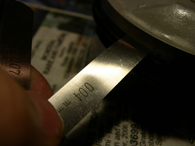
Here I am checking the ring gap. You put the rings at 56mm down into the barrel and then check the gap between the ends of the rings. There is a gap to allow the ring to expand when it gets hot. If the gap is too large you can loose compression and have oil blowby, too tight can jam up the piston. Mine were on the bottom of the spec which I expected since the barrels have very little wear.
Notice the little words "TOP" to indicate the top of the ring...they have an orientation and its not nice to put them in upside down....

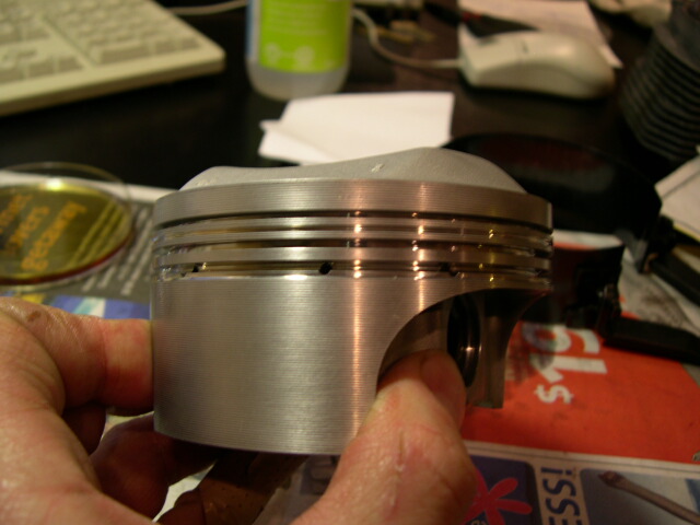
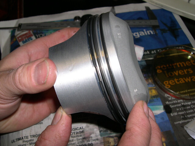
Here is the side shot of a piston. Notice that they put in a fourth groove starting on the 964 between the top and second compression rings.....as well as the nice machining. These pistons are nice very precision examples....
OK, putting the rings on. If you are experienced you can do this with your hands...I found that the top rings are very stiff and hard to do without damaging the piston so I used the tool very carefully.....just expand the ring to just make it over the top of the piston into its groove.
All three rings are in. Notice the bottom oil ring and its inner spring. The gaps are oriented away from each other with the oil ring bring to the top of the piston so no oil seeps past the ring when the engine is shut off.
Here I am checking the ring side clearance. This is the amount of slop the ring has in the groove on the piston. If its too large the piston is shot and you need a new set...at $5000 a set! Mine were at the bottom of the spec...ie. very good shape.
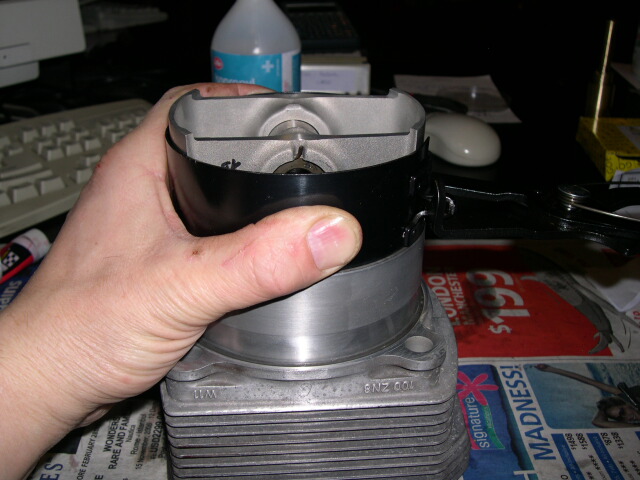
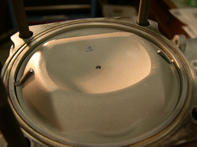
Ok, time to push that piston in. Here I am holding down the ring compressor with the rings compressed into the heads. I then tapped the piston into the barrel with light taps of a nylon hammer. It was tricky since you have to hold the ring compressor tight to the barrel so the rings don't excape....I had some pop out but I went pretty slowly and got them all in fine.
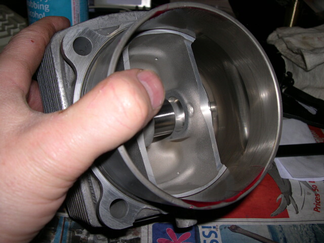
OK, piston is into the barrel. You can also see the wrist pin and the very nice machine work...
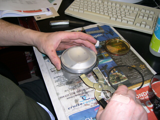
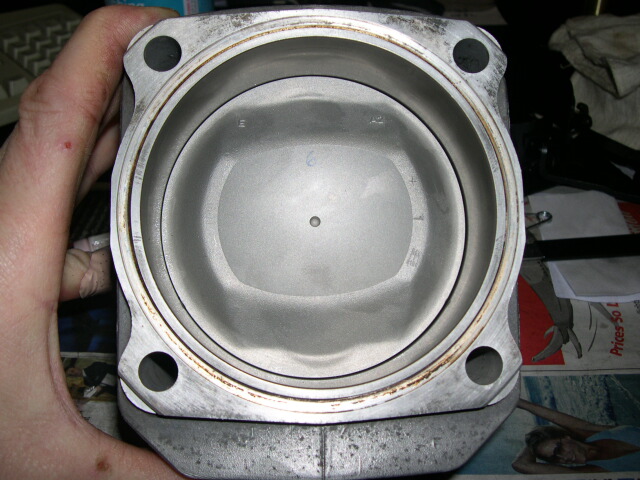
View from the top. The top of the piston is where the "E" is which stands for the intake....(in German of course).
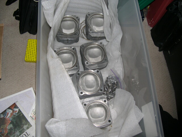
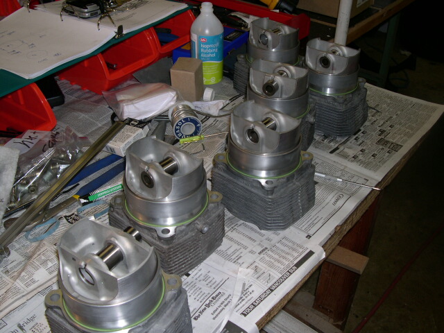
Ok, all pistons in the barrels ready in the box ready to be put onto the engine...I can almost hear the rmmmm rmmmm noise!
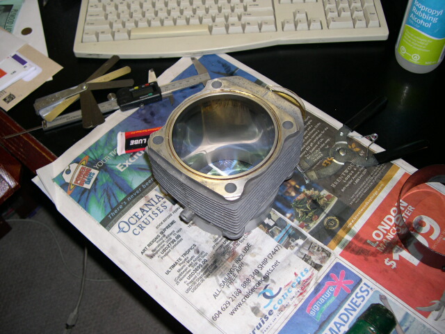
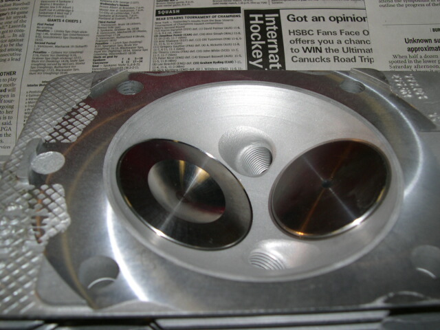
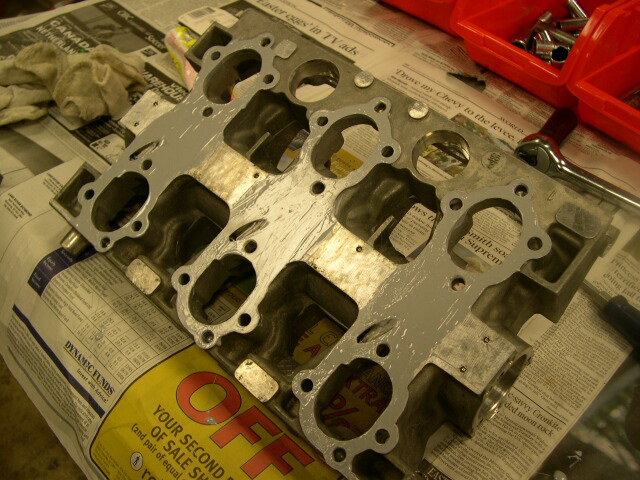
I was asked for some shots of the heads...here are mine before putting them on. Its a shame to hide this stuff. Notice that a few thou were taken off the heads to flatten them. My heads have all new guides and valves.
A side shot of a piece of art....

Next check is for the clearance between the piston and the heads. You do this with solder...yes PLUMBING SOLDER. I took too small pieces on each side of the piston while it was near TDC, put the head on and rotated the piston through TDC. The solder, being soft, squishes down and the thickness of the solder indicates the clearance between the head and the piston...pretty clever eh...not my idea! Anyways I checked both sides, pistons 1 and 4 and both are good.
After the clearance check I put on new viton gaskets and put all the wrist pins in...these pistons/cylinders are all ready for installation.
Here is my fancy tool which holds the clip in a compressed state ready to insert the clip. It worked great and only my palm pressure was needed to have the clip go in...it made it a pleasure to install the pistons.

The wrist pins are lubed up as well as the wrist pins with assembly lube. You also have to install the pistons in the right order so the wrist pin clip tool can clear the case....wrong way and you will have to start all over again!
Notice the lube on the skirts of the pistons...they will rub and need to be lubed. This is the position of the piston for installation....almost out of the barrel in order to have enough clearance to slide the wrist pin in. The piston usually does not run this low in the barrel of course...

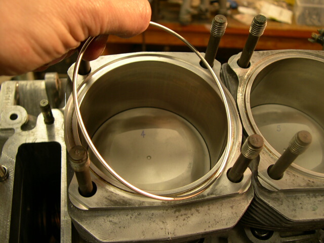
This is the metal sealing ring between the heads and the barrels....just make sure everything is nice and clean and assemble.
OK, heads are on this side. The head nuts are lightly tightened down. The cam towers go on first and are tightened down and then the heads are tightened down. If you don't do it this way you will never get the cam towers on since they have to align with pins with the heads...
The cam towers wich hold the cams and the rockers etc. are sealed with sealer. This is a common leak spot on 911's so its important that its both perfect and the gasket material is good. I used Threebond for this because I like it better than the Titebond products. I tested both and the Threebond gasket sealer (developed for motorcycles) is great...and Porsche used it on their race cars..
Notice the small area of gasket between the cam tower and the SAI vent. This is why I worry about blowing 100+ PSI of air though this heads......damaging this gasket would not be pretty...
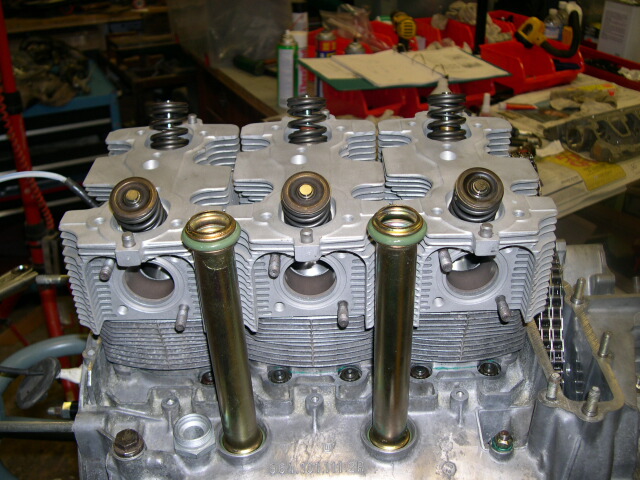
Heads are nice and clean and ready for the cam towers. The oil return tubes are in place......notice the nice clean new Viton seals (and new tubes of course)....oooooo I like a clean engine~! (yes, I am a sick man).
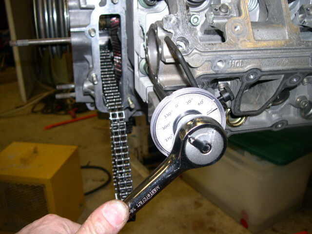
Once the cam towers are bolted down you torque down the heads. On the 993 its a light torque (17 ft-lbs) and then a 90 degree swing of the wrench. This is the tool I used to measure the 90 degrees...you can see that its on 90 now. I zeroed the guage before tightening the heads down..
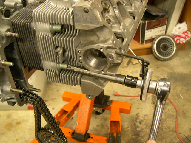
Another shot of tightening down the heads...you can see how the angle gauge holds onto the cam tower so the angle is measured relative to the case.
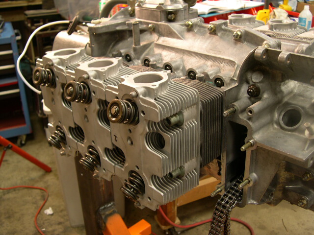
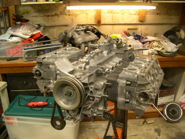
Heh it starting to look like an engine again!!
WOW, that was a lot of work but I am almost on the home stretch. The next installment is installing the cams, installing the older 964 style sprockets and timing the cams....then its the final assembly!
OK and here is the bonus prize. Can you spot where I screwed up terribly and had to redo a lot of work? Braggin' rights to those who spot the mistake!
Cheers,
Mike
Sorry for the big time gap, things have been moving slow and I just got back from spring break in Maui (yeah, someone has to do it).
This episode covers assemblying the pistons/cylinders, heads and cam towers...lots of work and prone to errors.
First of all I had to machine a tool to insert the wrist pin clips. They are really stiff and hard to do without the tool...so I fired up the lathe to machine the tool. Of course this means I had to INSTALL and WIRE the lathe since it was not running yet, and then get the right cutting tools, and then machine the piece out. Worked out great in the end though...and the tool works slick. Unfortunately I don't have a lot of shots of it and I have lent it out to another 911 engine DIY'er in town.
Here is a barrel ready for its piston...I liked this shot because of the neat gleam on the surface of the barrel.
The rings come in seperately wrapped packages. I found the most difficult ring to be the oil ring...its fragile and you have to keep the inner spring inside properly. I installed and removed the rings a few times to both get the feel and to see than nothing breaks....all seemed to be OK. The top and second rings (compression) have an orientation that you have to watch for.
Oh, notice in the background the wrist pin tool I made.......
Here I am checking the ring gap. You put the rings at 56mm down into the barrel and then check the gap between the ends of the rings. There is a gap to allow the ring to expand when it gets hot. If the gap is too large you can loose compression and have oil blowby, too tight can jam up the piston. Mine were on the bottom of the spec which I expected since the barrels have very little wear.
Notice the little words "TOP" to indicate the top of the ring...they have an orientation and its not nice to put them in upside down....
Here is the side shot of a piston. Notice that they put in a fourth groove starting on the 964 between the top and second compression rings.....as well as the nice machining. These pistons are nice very precision examples....
OK, putting the rings on. If you are experienced you can do this with your hands...I found that the top rings are very stiff and hard to do without damaging the piston so I used the tool very carefully.....just expand the ring to just make it over the top of the piston into its groove.
All three rings are in. Notice the bottom oil ring and its inner spring. The gaps are oriented away from each other with the oil ring bring to the top of the piston so no oil seeps past the ring when the engine is shut off.
Here I am checking the ring side clearance. This is the amount of slop the ring has in the groove on the piston. If its too large the piston is shot and you need a new set...at $5000 a set! Mine were at the bottom of the spec...ie. very good shape.
Ok, time to push that piston in. Here I am holding down the ring compressor with the rings compressed into the heads. I then tapped the piston into the barrel with light taps of a nylon hammer. It was tricky since you have to hold the ring compressor tight to the barrel so the rings don't excape....I had some pop out but I went pretty slowly and got them all in fine.
OK, piston is into the barrel. You can also see the wrist pin and the very nice machine work...
View from the top. The top of the piston is where the "E" is which stands for the intake....(in German of course).
Ok, all pistons in the barrels ready in the box ready to be put onto the engine...I can almost hear the rmmmm rmmmm noise!
I was asked for some shots of the heads...here are mine before putting them on. Its a shame to hide this stuff. Notice that a few thou were taken off the heads to flatten them. My heads have all new guides and valves.
A side shot of a piece of art....
Next check is for the clearance between the piston and the heads. You do this with solder...yes PLUMBING SOLDER. I took too small pieces on each side of the piston while it was near TDC, put the head on and rotated the piston through TDC. The solder, being soft, squishes down and the thickness of the solder indicates the clearance between the head and the piston...pretty clever eh...not my idea! Anyways I checked both sides, pistons 1 and 4 and both are good.
After the clearance check I put on new viton gaskets and put all the wrist pins in...these pistons/cylinders are all ready for installation.
Here is my fancy tool which holds the clip in a compressed state ready to insert the clip. It worked great and only my palm pressure was needed to have the clip go in...it made it a pleasure to install the pistons.
The wrist pins are lubed up as well as the wrist pins with assembly lube. You also have to install the pistons in the right order so the wrist pin clip tool can clear the case....wrong way and you will have to start all over again!
Notice the lube on the skirts of the pistons...they will rub and need to be lubed. This is the position of the piston for installation....almost out of the barrel in order to have enough clearance to slide the wrist pin in. The piston usually does not run this low in the barrel of course...
This is the metal sealing ring between the heads and the barrels....just make sure everything is nice and clean and assemble.
OK, heads are on this side. The head nuts are lightly tightened down. The cam towers go on first and are tightened down and then the heads are tightened down. If you don't do it this way you will never get the cam towers on since they have to align with pins with the heads...
The cam towers wich hold the cams and the rockers etc. are sealed with sealer. This is a common leak spot on 911's so its important that its both perfect and the gasket material is good. I used Threebond for this because I like it better than the Titebond products. I tested both and the Threebond gasket sealer (developed for motorcycles) is great...and Porsche used it on their race cars..
Notice the small area of gasket between the cam tower and the SAI vent. This is why I worry about blowing 100+ PSI of air though this heads......damaging this gasket would not be pretty...
Heads are nice and clean and ready for the cam towers. The oil return tubes are in place......notice the nice clean new Viton seals (and new tubes of course)....oooooo I like a clean engine~! (yes, I am a sick man).
Once the cam towers are bolted down you torque down the heads. On the 993 its a light torque (17 ft-lbs) and then a 90 degree swing of the wrench. This is the tool I used to measure the 90 degrees...you can see that its on 90 now. I zeroed the guage before tightening the heads down..
Another shot of tightening down the heads...you can see how the angle gauge holds onto the cam tower so the angle is measured relative to the case.
Heh it starting to look like an engine again!!
WOW, that was a lot of work but I am almost on the home stretch. The next installment is installing the cams, installing the older 964 style sprockets and timing the cams....then its the final assembly!
OK and here is the bonus prize. Can you spot where I screwed up terribly and had to redo a lot of work? Braggin' rights to those who spot the mistake!
Cheers,
Mike


 03-21-2006, 03:15 AM
#3
Instructor
Join Date: Jul 2003
Location: Seattle
Posts: 211
Likes: 0
Received 0 Likes
on
0 Posts
An incdedible journey Mike, you must feel great (and rightfully so) being so close to the end of the line. I'd feel comfortable having you do a rebuild on my engine. Your attention to detail and mechanical creativity is really noteworthy.
Ah, for the bonus question, its just a guess as I am merely a student of Porsche engines, but the cam missing on the right bank would be my bet?
Great work as usual,
Jeff N.
Ah, for the bonus question, its just a guess as I am merely a student of Porsche engines, but the cam missing on the right bank would be my bet?
Great work as usual,
Jeff N.


Trending Topics
03-21-2006, 11:47 AM
#8
Addict
Lifetime Rennlist
Member
Lifetime Rennlist
Member
Thread Starter
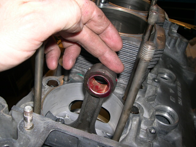
The camshaft missing on the right is not the answer since they just slide in. Hint: There is a fair amount of disassembly to fix the problem. It might be too sublte though since it shows up in only one picture. (another hint...look at picture #23)........ ;-)
Cheers,
Mike
Cheers,
Mike
03-21-2006, 12:22 PM
#10
Addict
Rennlist Member
Rennlist Member
Join Date: Aug 2001
Location: Tucson AZ
Posts: 246
Likes: 0
Received 0 Likes
on
0 Posts
The "air ducts" are missing under the cylinders..... so the cam housings must come back off? My best guess since I can't go crawl under my car; I drove the truck to work today!
Mike, thanks for the whole series of posts.... they will be of monumental help when I go thru my engine (hopefully not for a while).
Cheers, Mark.
Mike, thanks for the whole series of posts.... they will be of monumental help when I go thru my engine (hopefully not for a while).
Cheers, Mark.
03-21-2006, 12:52 PM
#11
Addict
Lifetime Rennlist
Member
Lifetime Rennlist
Member
Thread Starter
Originally Posted by MadMarkie
The "air ducts" are missing under the cylinders..... so the cam housings must come back off? My best guess since I can't go crawl under my car; I drove the truck to work today!
Mike, thanks for the whole series of posts.... they will be of monumental help when I go thru my engine (hopefully not for a while).
Cheers, Mark.
Mike, thanks for the whole series of posts.... they will be of monumental help when I go thru my engine (hopefully not for a while).
Cheers, Mark.
1 - Cut the oil return tubes off and use expandable ones as replacements. This did not appeal to me at all. Too much of a purist I guess...(and I hate to admit mistakes).
2 - Unbolt the head bolts, slide all three cylinders up so the oil return tubes can be removed and then reassemble. This may be the easiest but I did not want to distrurb the new head sealing rings.
3 - Remove the cam towers, cleanup all the sealant, put in the air deflectors and then re-install the cam towers. I also wanted to check how the Threebond sealer worked...turned out it works great and I will post pictures next thread on what it looked like when taken apart. I lost about 4 hours on this one (or unil 2:30AM whichever way you want to look at it!).
Anyways back to work. I have done all the cam timing but will recheck this morning since I was away for the last 10 days. Then I need to check the valve/piston clearances, if that checks out (and it should) I can install all the rockes, button up the cam covers and valve covers and start on the external assembly. That will be the topic of my next post....
Cheers,
Mike
03-21-2006, 01:31 PM
#13
Race Car
Mike:
Nice build. The final check for the sport seats went out today next day air via UPS. You should get on Wednesday. I sent you an email as well. BTW love the sport seats
Mike
Nice build. The final check for the sport seats went out today next day air via UPS. You should get on Wednesday. I sent you an email as well. BTW love the sport seats
Mike
03-21-2006, 02:15 PM
#15
Addict
Rennlist Member
Rennlist Member
Join Date: Aug 2001
Location: Tucson AZ
Posts: 246
Likes: 0
Received 0 Likes
on
0 Posts
EXACTLY RIGHT! Congratulations Mark you win the bragging rights!
 All that time on my back under the engine lately seems to be paying off.... last night I succeeded in flowing air thru all 6 SAI ports, and now this!!!! Saweeet!