When you click on links to various merchants on this site and make a purchase, this can result in this site earning a commission. Affiliate programs and affiliations include, but are not limited to, the eBay Partner Network.
I also have a similar random "phut" sound out of the left exhaust tip. The idle is just barely rough when hot and without A/C on. If cold or with A/C, and it smooths out.
exactly the same symptom. turn on the A/C and it gets smoother.
Like i mentioned, i found a correlation between the "phut" sound and the intake rockers/lifters which are currently on bank 1. The lifters and rocker arms are all new so i am not sure how i will isolate the culprit.
George, I have a couple of ideas on this to run by you.
If I read the first post correctly, the PO had a chipped ECU in the car and
the engine idled smoothly yet pinged when accelerating. You removed the
chipped ECU for a standard ECU and now the car idles rough. My suspicion
is that the chipped ECU enriched the idle mixture and gave a better idle.
The pinging may have actually been the valves rattling because the valve guides
were worn and not actually due to knock (pinging). The standard ECU runs a
very lean fuel mixture at idle in order to meet emissions requirements.
This combined with a high compression ratio can lead to intermittent misfires.
So one idea would be to return the chipped ECU to the car and see how it idles.
With the new valve guides the valves shouldn't rattle.
Did you "blue-print" the cam to the new rockers? In this post by Steve W. he
addresses an issue with the mating surfaces:
In terms of how to test and isolate the problem further, I would look to using
pressure transducers to get a dynamic view of the mechanical integrity of the
engine. Here are some links that provide info on misfire detection using
pressure transducers:
As to who can do this sort of diagnosis locally, you might try Tony Callas
at Callas Rennsport in Torrance. There is a shop in Santa Barbara that
has the equipment, http://www.ayersrepairs.com, but when I spoke to
them by phone they had not tried it on a Porsche 993. There may be
others but I haven't done the research beyond that. Of course you could
also go to Albuquerque, N.M. where Bernie Thompson is located.
do you hear the phut in both banks? What is the idle quality like?
Yes, both banks. It idles fine as long as I don't focus on it.
Aside from the sound, there are no operational issues.
You can feel an occasional light shake when stopped and idling.
The idle improves when the air conditioning is switched on.
The idle also improves when the headlights are switched on.
George, I have a couple of ideas on this to run by you.
If I read the first post correctly, the PO had a chipped ECU in the car and
the engine idled smoothly yet pinged when accelerating. You removed the
chipped ECU for a standard ECU and now the car idles rough. My suspicion
is that the chipped ECU enriched the idle mixture and gave a better idle.
The pinging may have actually been the valves rattling because the valve guides
were worn and not actually due to knock (pinging). The standard ECU runs a
very lean fuel mixture at idle in order to meet emissions requirements.
This combined with a high compression ratio can lead to intermittent misfires.
So one idea would be to return the chipped ECU to the car and see how it idles.
With the new valve guides the valves shouldn't rattle.
Did you "blue-print" the cam to the new rockers? In this post by Steve W. he
addresses an issue with the mating surfaces:
In terms of how to test and isolate the problem further, I would look to using
pressure transducers to get a dynamic view of the mechanical integrity of the
engine. Here are some links that provide info on misfire detection using
pressure transducers:
As to who can do this sort of diagnosis locally, you might try Tony Callas
at Callas Rennsport in Torrance. There is a shop in Santa Barbara that
has the equipment, http://www.ayersrepairs.com, but when I spoke to
them by phone they had not tried it on a Porsche 993. There may be
others but I haven't done the research beyond that. Of course you could
also go to Albuquerque, N.M. where Bernie Thompson is located.
Good luck with the car,
-bruce7
Bruce,
Thanks for the reply. Lots of great interesting information.
I don't have the ECU with the chipped code any longer since I had it reprogrammed instead of replacing it. That is why I reached out to Loren of systems Consulting to do a test with one of his known good working units. As mentioned this confirmed the ECU reprogramming was good.
I am under the impression that nothing can be done to alter the mixture when the o2 sensors are in "closed loop". Would like to hear if that is not the case. Even changing the rich/lean threshold of 0.45v wouldn't do anything since the curve is so steep at the transitions.
I did not blue-print anything. Please keep in mind that prior to installing new rockers I installed new lifters in the original rocker arms and put them back on same location from where they were removed. There was an improvement but still had a "phut" sound as in my first video. Then I installed all new rockers and new lifters which made the biggest improvement, second video. I think steve's post is more about even pad wear rather than deviations in valve timing although that argument can be made.
Great idea to use pressure sensors to locate the misfire cylinder(s). I was thinking of using an oscilloscope to look at fluctuations in rpms at the crank sensor just like the ECU checks for misfires. In fact I found a oscilloscope manufacturer who is willing to do something so that I can stream and save data. This would be an alternative unit to an expensive PICO unit with a large buffer memory.
In the meantime, I am finally enjoying the 993 after 1.5 years of buying and rebuilding it. Even with the few "phuts".
I am under the impression that nothing can be done to alter the mixture when the o2 sensors are in "closed loop". Would like to hear if that is not the case. Even changing the rich/lean threshold of 0.45v wouldn't do anything since the curve is so steep at the transitions.
I did not blue-print anything. Please keep in mind that prior to installing new rockers I installed new lifters in the original rocker arms and put them back on same location from where they were removed. There was an improvement but still had a "phut" sound as in my first video. Then I installed all new rockers and new lifters which made the biggest improvement, second video. I think steve's post is more about even pad wear rather than deviations in valve timing although that argument can be made.
Great idea to use pressure sensors to locate the misfire cylinder(s). I was thinking of using an oscilloscope to look at fluctuations in rpms at the crank sensor just like the ECU checks for misfires. In fact I found a oscilloscope manufacturer who is willing to do something so that I can stream and save data. This would be an alternative unit to an expensive PICO unit with a large buffer memory.
George, Yes with the narrow-band O2 sensors in closed-loop they will try to
keep the AFR to 14.7. I think chip reprogrammers will normally use the factory
idle fuel and ignition maps, but, there may be a way around that. I'll check
into it and see.
Someday I would like to drive a 993 with a wide-band O2 sensor and MoTec
engine management to see what we are missing!
My comment about matching the cam to the rocker was less about the misfire
("phut" sound) than about potential wear and mechanical "goodness". I
understood Steve's comment to mean that accelerated cam lobe wear might
occur with new rockers that don't mate properly to the old cam lobe due to
quality control issues at the factory with the rocker pads. Steve has way to
make sure the angles match.
That's what I referred to as "blue-printing". If you have it apart it might be
worth checking into before putting it back together again.
Checked into the question of whether or not you could modify the fuel
map and make it run richer at idle with a reprogramming shop and they
said basically no. If the car is misfiring at idle it has some issue that
needs to be tracked down. Could be an air leak, ignition related, etc.
Seems to be such a common problem to almost seem normal. This
would make a good diagnostics case study that would be of interest to
many 993 owners.
thanks for looking into this. That is what i suspected. I also agree that something is not correct and needs to be tracked down. I am going to stick my neck out and guess that the root problem is related to inconsistent or out of spec inlet valve timing due to the "finger" type lifters used in our 993's. I plan to dig deeper and will you know if i find anything else.
I have a Actron scan tool (Autoscanner CP 9575) and it can't read Mode 6
data. Checking on the Actron website shows that they do have models
that can read Mode 6. Someday I need to upgrade to a better scan tool,
although I doubt that it will be another Actron. I'd like to get the ATS
EScan Pro. More money but a very powerful tool:
If you can read and decode Mode 6 data then you will be able to see which
cylinders are misfiring but not yet reported by OBDII (by setting the CEL)
because the reporting threshold hasn't been reached. It's like early-warning
data.
I think that the "phut" sound should be marked as a misfire. If so, this
will be a great way to quickly isolate the area where to look for the problem.
-bruce7
Update on scan tool support for Mode 6:
Durametric does not support Mode 6. ($287) (Had to call to verify)
Action Autoscanner CP9670 does support Mode 6. ($177)
ATS EScan Pro supports Mode 6. ($995)
Last edited by bruce7; 06-24-2016 at 06:59 PM.
Reason: revised with 2 more articles and other wording and update on scan tools support for mode 6 and price
From a private message I received, it's believed that the PST2 does support
Mode 6. However, I haven't been able to confirm this since I myself don't
have access to a PST2 scan tool.
The question then is if it is able to decode the hex codes into English. Turns
out this is something that can't be taken for granted.
I did find that in the ATS EScan user manual that when looking at Mode 6 data,
the monitors must be complete for related Mode 6 info to be accurate. Also, if
DTCs have been recently cleared, there will be no Mode 6 data available.
ATS has a new Mode 6 decoder that can be use to translate Mode 6 hex codes
to English:
That's what I referred to as "blue-printing". If you have it apart it might be
worth checking into before putting it back together again.
I suspect Steve has the rockers mounted on their pivot bores and grinds the rocker pads parallel to the centerline of the pivot bore, which is the datum reference of the rocker.
Difficult to imagine how the factory gets this wrong, unles the paraellelism alignment issue resides elsewhere.
I have a Actron scan tool (Autoscanner CP 9575) and it can't read Mode 6
data. Checking on the Actron website shows that they do have models
that can read Mode 6. Someday I need to upgrade to a better scan tool,
although I doubt that it will be another Actron. I'd like to get the ATS
EScan Pro. More money but a very powerful tool:
If you can read and decode Mode 6 data then you will be able to see which
cylinders are misfiring but not yet reported by OBDII (by setting the CEL)
because the reporting threshold hasn't been reached. It's like early-warning
data.
I think that the "phut" sound should be marked as a misfire. If so, this
will be a great way to quickly isolate the area where to look for the problem.
-bruce7
Update on scan tool support for Mode 6:
Durametric does not support Mode 6. ($287) (Had to call to verify)
Action Autoscanner CP9670 does support Mode 6. ($177)
ATS EScan Pro supports Mode 6. ($995)
Good info Bruce. The pst2 has a generic tool mode and I will see if it reads mode 6. If it does, you have a good point about monitoring misfires.
I did buy that pc based oscilloscope and took about 70 seconds of crankshaft sensor data. There are 58 pulses per revolution. The challenge is how to analyze the data using Excel. There are about 300,000 data samples. If i can't manipulate the data easily i plan to get a pressure transducer, like in the ATS video, and try that method. This ought to reduce the number of samples to be analyzed significantly since there will be 1 event per 240 crank degrees, if i did the math correctly, much less than 58 per rev.
thanks
George,
How are you thinking of using Excel? I'm not an Excel user so can't offer
much help there. Can you graph the data using Excel? I'm guessing that
you want to see if there is a glitch in the waveform? Let's say there was a
glitch in the waveform. What would be possible causes? RPM sensor, failing
DMF?
I know that earlier you said you checked the DMF using the 15mm rotation
test and it checked out ok. There is another test for the DMF that I read
about where you put the car on a lift and let it idle in first gear. Then
check the rpm sensor. Supposedly, a failing DMF will show wildly fluctuating
rpm values. They used a scan tool to read the rpm. An oscilloscope could
also be used and should show a glitch in the waveform.
On the transducer idea, I'm all for that approach. There is a training DVD
put out by ATI on the subject that might be worth checking out:
And here is a video of John Thornton diagnosing a engine with rough idle
which ended up being the result of cam timing being off:
One question I have is how useful is the pressure transducer when used
with an oscilloscope without the special purpose analysis software that is
part of the ATS or PicoScope systems?
Another question is how many transducers do you need? I think there is
a demo video of ATS using more than one transducer to diagnose a misfire.
(They can be used in-cylinder, in-manifold, and in-exhaust.) That's where
viewing the training material before purchase could be beneficial.
I will look into the points you raised later but in the meantime let me show you what i have done.
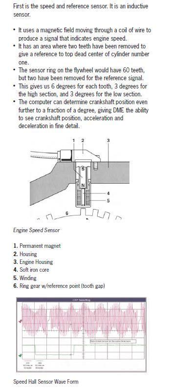
Below is from the manual and shows the pulses from the flywheel reference teeth and hall sensor in the distributor.
So i thought that if i captured the data i could calculate the time between each tdc and the slowest time would indicate a misfire. I believe this is what the DME does.
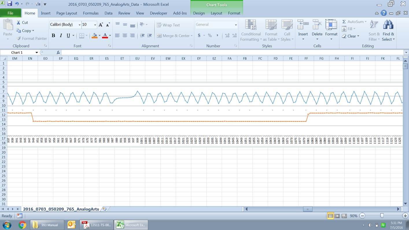
Below is a chart of the data that i captured which as you can see resembles the chart above. The peaks of the blue graph are the teeth on the ring gear passing the sensor and the orange line is the hall sensor. TDC for cylinder 1 is when the orange voltage drops and the gap in the blue line is where the teeth are missing on the ring gear.
If I did the math properly, a TDC in for the firing order occurs every 20 teeth which shows as peaks in the blue line. Cylinder 1, then 6 and so on...
The challenge now is how to analyze 300,000 data points (approx. 70 seconds of data while idling). The data in the chart below is only 50 ms of data. Using Excel to do the math automatically is more difficult than i thought and there is way too much data to scroll through.
I will keep you posted and welcome any suggestions.
So i thought that if i captured the data i could calculate the time between each tdc and the slowest time would indicate a misfire. I believe this is what the DME does.
The challenge now is how to analyze 300,000 data points (approx. 70 seconds of data while idling). The data in the chart below is only 50 ms of data. Using Excel to do the math automatically is more difficult than i thought and there is way too much data to scroll through.
So if I follow you, the idea is to determine which cylinder is misfiring. And your
approach is to try and replicate what the DME does to calculate a misfire.
But is that really what the DME does? I thought what the DME did was to
calculate the angular velocity (rate of speed change) between successive cylinders.
Then it must apply a correction factor for whether the engine is accelerating or decelerating.
I don't have any reference to point to for how the DME does misfire detection
so this is just speculation. I did find though a patent abstract for misfire
detection that is interesting reading and I'm sure that there is a lot more
out there:
Other approaches that would be easier would include: spark line firing
waveforms, O2 sensor waveforms, pressure transducer waveforms,
and Mode 6 diagnostics.
 06-20-2016, 08:19 PM