Engine Rebuild Part 3 (the finale)
 01-16-2012, 09:01 PM
#61
Three Wheelin'
Thread Starter
Preparing to mate the case halves. Cleaning everything is ongoing. In the case of the cylinders it is critical. They have already been scrubbed, cleaned with hot water & dish soap, cleaned some more, more compressed air, more cleaning. For the final cleaning, I take some accuwipes (like them better than kim wipes b/c they are thicker), and denatured alcohol and rub the cylinders until there is absolutely no residue on the wipes when they come out (left wipe residue, right wipe no residue).


The inspection proceeds with a final up close inspection with a flashlight, up close in all of the oil galleries, water passageways, looking for any casting flash or any debris that might cause a problem. The mating surfaces of the case halves are cleaned again with acetone, and the mating surfaces of the bearing carrier and case halves are cleaned. Even though the threads were cleaned prior to shipping to LNE, I chase them again. The water channel gaskets are placed into the 1-3 halves.


Preparing to apply the drei bond. I had to raise the temp to about 65 in order to apply this, it says over 59 degrees. I measured out appx 1.32mm bead.

Before applying any silicone, make sure you are 100% ready to drop the case half on. You need a helper. The pins and sleeves need to be in place. You need to have the new bolts ready to insert. Study where to apply the bead of silicone and have the diagram right next to you during application. There is very little time to work with once you start dispensing the silicone. I put accuwipes between the rods to hold them in a vertical position so they don't get in the way during lowering of the half. The 4-6 chain is carefully folded onto itself so it rests out of the way and can be picked out of the chain box later.

And the next part is magic. There's no time to take pictures. The silicone goes on, and carefully lifting and setting the case half in place set into the align pins and sleeves. Then bolts go on, torqued per the WSM and in a specific sequence. Then a sigh of relief.


Inspecting the oil scraper gaskets from the sump to make sure they are correctly seated after mating the halves.

Tomorrow, the REAL fun begins!

The inspection proceeds with a final up close inspection with a flashlight, up close in all of the oil galleries, water passageways, looking for any casting flash or any debris that might cause a problem. The mating surfaces of the case halves are cleaned again with acetone, and the mating surfaces of the bearing carrier and case halves are cleaned. Even though the threads were cleaned prior to shipping to LNE, I chase them again. The water channel gaskets are placed into the 1-3 halves.
Preparing to apply the drei bond. I had to raise the temp to about 65 in order to apply this, it says over 59 degrees. I measured out appx 1.32mm bead.
Before applying any silicone, make sure you are 100% ready to drop the case half on. You need a helper. The pins and sleeves need to be in place. You need to have the new bolts ready to insert. Study where to apply the bead of silicone and have the diagram right next to you during application. There is very little time to work with once you start dispensing the silicone. I put accuwipes between the rods to hold them in a vertical position so they don't get in the way during lowering of the half. The 4-6 chain is carefully folded onto itself so it rests out of the way and can be picked out of the chain box later.
And the next part is magic. There's no time to take pictures. The silicone goes on, and carefully lifting and setting the case half in place set into the align pins and sleeves. Then bolts go on, torqued per the WSM and in a specific sequence. Then a sigh of relief.
Inspecting the oil scraper gaskets from the sump to make sure they are correctly seated after mating the halves.
Tomorrow, the REAL fun begins!
Last edited by logray; 01-17-2012 at 12:10 PM.


 01-20-2012, 12:50 AM
#67
Three Wheelin'
Thread Starter
Hah, thanks guys. I'm starting a "waiting list" for rebuilds. (kidding) First things first is to get my car back on the road and out of the driveway. 
Had some time today for the car !!! Can't wait... getting very close. Big update.
First things first, from where I left off, with the alignment tool in the #6 rod. Before getting that far ahead of myself, some careful "indexing" preformed beforehand.
If you think you can just waltz in and complete the 4-6 cylinder wrist pin clips without doing any math or measurements or careful thought you are foolish and fool-hearty. BEFORE even thinking about attempting this, you need a.) practice (as Jake lays out on his engine build site), b.) guts, c.) skills, d.) brains, and e.) plenty of time spent observing how to use the insertion tools. If you have NEW TOOLS, you MUST index them !!!! Or at the very least take measurements and know how to use them. Otherwise, you will waste a ton of time as your clips go springing around in your crank case wasting hours and hours of time to disassemble, retrieve clip, clean, inspect, clean some more, reassemble the case half, piston, align, reinsert piston and back where you were before you lost the clip. So..... measurements shall we?
First off, here is what you have to work through. A little hole. Great. Seriously though, you can "sorta" work through the adjacent cylinder, but all of the business is done through that hole. AND BLIND!!!!

First with the 4-6 case half on the bench, take your clip insertion tool and feed it through with a piston test fitted in #6. No need for a clip here. What you're trying to see is how far in the insertion tool needs to go (FULLY) into the side of the piston.

This is so you KNOW 100% when you are going to put the clip in how far the insertion tool needs to go.


Here, with the case on the bench, it's very easy to see how the tool seats and where it needs to go before you attempt clip insertion. You can use mirrors...

Even "peek" through the hook slot on the side of the tool to see if it is fully seated against the piston where it needs to be.

Next you insert another tool into the clip retaining tool until it reaches the stop, and then make some marks. These marks will help you know 10000% how far in you need to go before you even attempt to hammer in that clip.


Repeat the measurement and indexing process for each of the pistons, noting both how far in the clip retaining tool and the insertion sleeve need to go in.


Once your tools are ready, go for it. First, insert the piston into the cylinder. LNE's tapered ring compressor is great. I can see where in a production line it would be quick and easy to use. Rings carefully cleaned, installed, and lubed. Piston lubed, insertion tool lubed, cylinder lubed, everything cleaned one last time before hand, and engine turned to the appropriate location. Small rod bush lubed.

Once the piston is pushed down to the alignment tool, time to flip over the engine so the 4-6 half/bank 2 faces to the ground. At this point, gravity will help keep the rod aligned and straight before you install the piston wrist pin. Level the top of the engine, then insert a boroscope through the installation hole so you can see the alignment between the piston and rod. Carefully tap the piston so it is as close as possible with the small rod bush bore. You can use the alignment tool to insert, twist, rotate, and get it close. Boroscope and mirror to get it close. Then put a wrist pin on the end of the insertion tool and push it through the piston into the small rod bush bore and against the pin clip on the other side of the piston (that you installed before putting the piston in the cylinder). Once the pin is pushed fully against the clip on the back side of the piston, verify with boroscope and mirror. You should see the oil grooves in the piston in front of the wrist pin. Otherwise, the pin is not in far enough and the clip installation could fail.


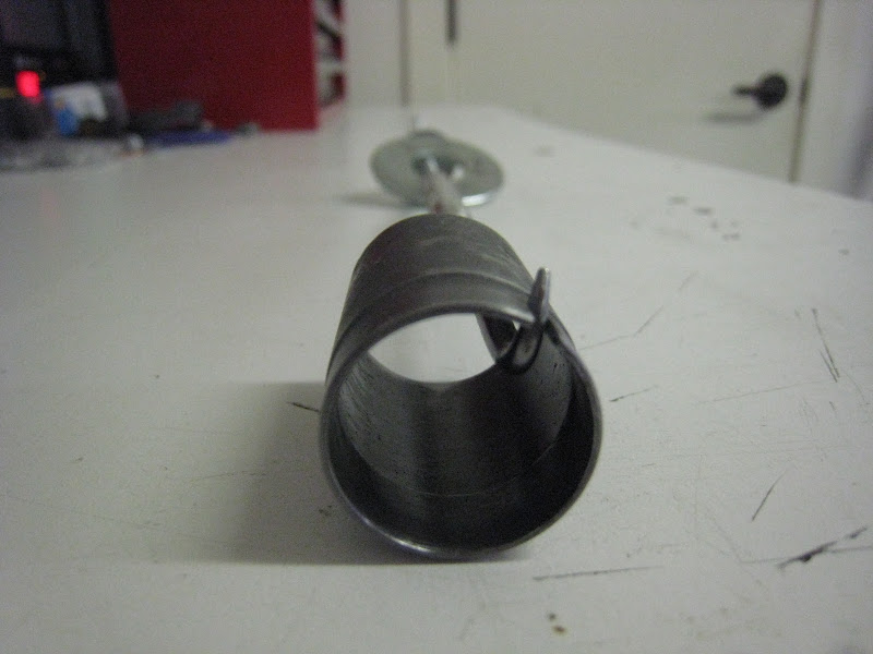
Load the clip into the insertion tool (I chickened out and removed the hook, followed by a pic of the slightly ground off hook compared with the full hook).


After the pin is in, flip the engine back over and get ready to insert the clip. First feed the insertion tool into the hole as far as it will go.

From here, you have the luxury of aligning the slot with the hole in the piston for the hook. You can use mirrors, boroscope, and rotate the insertion tool by hand until it is perfectly aligned. You can even use a standard boat plug to rotate the tool. Of course, without a hook on the clip, it is less a worry!

But... this is not far enough. Careful indexing and marking before hand indicates this is not far enough into the piston. The clip installation will fail.
It requires some more "help" with a hammer carefully tapping on the end of the insertion sleeve until it reaches the marks you made before sealing the case half onto 1-3 bank 1. The sleeve will stop inside of the insertion tool and not push the clip out of it. Hammer gently, regardless... The line I made on the tool should be exactly flush with the case surface. There are other ways to accomplish this as well, such as how Jake did it with a wire bolted onto the case.


Once the insertion tool is all the way in and ready to accept some force, it's time to put in the driver and pound it in with a swift smack. It's terrifying and gratifying all at the same time. The only way to know if you are truly 100% successful is a.) your index marks and b.) LOOKING at the clip with your mirror and boroscope. This is number 6.


Next remove the insertion tool from the piston. A hook on the end of a long threaded rod allowed for grabbing onto the slot of the insertion tool and gently tugging it out of the piston, then plucking it out by hand from the adjacent cylinder. If the insertion tube tool was just a little longer, there would be enough purchase to get it out much easier (probably by hand), but this tool did the trick, too bad I didn't think of it until the last piston. Or if the alignment of the installation hole and piston were better... (different story). But long story short is the insertion tool came out without collateral damage and ready for the next piston.

#5 through the mirror and boroscope.


#4 is a "cake walk", since it's just a few inches from the outside of the case.

Short block nearly ready for the heads. At this point some seals, IMS flange, oil pump console, etc., heads, timing, simple !!!. Should be smooth sailing from here since I've been there done that a million times... seen my other threads???? LOL..
Had some time today for the car !!! Can't wait... getting very close. Big update.
First things first, from where I left off, with the alignment tool in the #6 rod. Before getting that far ahead of myself, some careful "indexing" preformed beforehand.
If you think you can just waltz in and complete the 4-6 cylinder wrist pin clips without doing any math or measurements or careful thought you are foolish and fool-hearty. BEFORE even thinking about attempting this, you need a.) practice (as Jake lays out on his engine build site), b.) guts, c.) skills, d.) brains, and e.) plenty of time spent observing how to use the insertion tools. If you have NEW TOOLS, you MUST index them !!!! Or at the very least take measurements and know how to use them. Otherwise, you will waste a ton of time as your clips go springing around in your crank case wasting hours and hours of time to disassemble, retrieve clip, clean, inspect, clean some more, reassemble the case half, piston, align, reinsert piston and back where you were before you lost the clip. So..... measurements shall we?
First off, here is what you have to work through. A little hole. Great. Seriously though, you can "sorta" work through the adjacent cylinder, but all of the business is done through that hole. AND BLIND!!!!
First with the 4-6 case half on the bench, take your clip insertion tool and feed it through with a piston test fitted in #6. No need for a clip here. What you're trying to see is how far in the insertion tool needs to go (FULLY) into the side of the piston.
This is so you KNOW 100% when you are going to put the clip in how far the insertion tool needs to go.
Here, with the case on the bench, it's very easy to see how the tool seats and where it needs to go before you attempt clip insertion. You can use mirrors...
Even "peek" through the hook slot on the side of the tool to see if it is fully seated against the piston where it needs to be.
Next you insert another tool into the clip retaining tool until it reaches the stop, and then make some marks. These marks will help you know 10000% how far in you need to go before you even attempt to hammer in that clip.
Repeat the measurement and indexing process for each of the pistons, noting both how far in the clip retaining tool and the insertion sleeve need to go in.
Once your tools are ready, go for it. First, insert the piston into the cylinder. LNE's tapered ring compressor is great. I can see where in a production line it would be quick and easy to use. Rings carefully cleaned, installed, and lubed. Piston lubed, insertion tool lubed, cylinder lubed, everything cleaned one last time before hand, and engine turned to the appropriate location. Small rod bush lubed.
Once the piston is pushed down to the alignment tool, time to flip over the engine so the 4-6 half/bank 2 faces to the ground. At this point, gravity will help keep the rod aligned and straight before you install the piston wrist pin. Level the top of the engine, then insert a boroscope through the installation hole so you can see the alignment between the piston and rod. Carefully tap the piston so it is as close as possible with the small rod bush bore. You can use the alignment tool to insert, twist, rotate, and get it close. Boroscope and mirror to get it close. Then put a wrist pin on the end of the insertion tool and push it through the piston into the small rod bush bore and against the pin clip on the other side of the piston (that you installed before putting the piston in the cylinder). Once the pin is pushed fully against the clip on the back side of the piston, verify with boroscope and mirror. You should see the oil grooves in the piston in front of the wrist pin. Otherwise, the pin is not in far enough and the clip installation could fail.
Load the clip into the insertion tool (I chickened out and removed the hook, followed by a pic of the slightly ground off hook compared with the full hook).
After the pin is in, flip the engine back over and get ready to insert the clip. First feed the insertion tool into the hole as far as it will go.
From here, you have the luxury of aligning the slot with the hole in the piston for the hook. You can use mirrors, boroscope, and rotate the insertion tool by hand until it is perfectly aligned. You can even use a standard boat plug to rotate the tool. Of course, without a hook on the clip, it is less a worry!
But... this is not far enough. Careful indexing and marking before hand indicates this is not far enough into the piston. The clip installation will fail.
It requires some more "help" with a hammer carefully tapping on the end of the insertion sleeve until it reaches the marks you made before sealing the case half onto 1-3 bank 1. The sleeve will stop inside of the insertion tool and not push the clip out of it. Hammer gently, regardless... The line I made on the tool should be exactly flush with the case surface. There are other ways to accomplish this as well, such as how Jake did it with a wire bolted onto the case.
Once the insertion tool is all the way in and ready to accept some force, it's time to put in the driver and pound it in with a swift smack. It's terrifying and gratifying all at the same time. The only way to know if you are truly 100% successful is a.) your index marks and b.) LOOKING at the clip with your mirror and boroscope. This is number 6.
Next remove the insertion tool from the piston. A hook on the end of a long threaded rod allowed for grabbing onto the slot of the insertion tool and gently tugging it out of the piston, then plucking it out by hand from the adjacent cylinder. If the insertion tube tool was just a little longer, there would be enough purchase to get it out much easier (probably by hand), but this tool did the trick, too bad I didn't think of it until the last piston. Or if the alignment of the installation hole and piston were better... (different story). But long story short is the insertion tool came out without collateral damage and ready for the next piston.
#5 through the mirror and boroscope.
#4 is a "cake walk", since it's just a few inches from the outside of the case.
Short block nearly ready for the heads. At this point some seals, IMS flange, oil pump console, etc., heads, timing, simple !!!. Should be smooth sailing from here since I've been there done that a million times... seen my other threads???? LOL..
Last edited by logray; 01-30-2012 at 01:06 PM.
 looking good logray
  01-20-2012, 11:34 AM
#70
Drifting
Logray
Thanks again for all the work you are doing documenting this. I realize how much extra time is required to take all the photos and to write everything up. Back in 2009 when I was undertaking the fix of my intermix I started with the intent to photograph and document every step. But that intent soon fell by the wayside as it could easily double the time involved.
I have always thought that Flat 6 should produce a DVD/Video on the rebuilding these engines to compliment the classes they offer. Maybe you should beat them to the punch. I for one would gladly pay to have this sort of documentation if I was undertaking a rebuild.
01-20-2012, 12:10 PM
#71
Three Wheelin'
Thread Starter
The rod stays in place by gravity, and a little lube. No joke. You flip the case upside down, and since the piston is at bottom dead center the rod is at a neutral point on the crankshaft centered in the cylinder. As long at the other side of the crank case is level the rod won't swing out of direction. There is an alignment tool you are supposed to feed through the piston into the rod, but I found the tools that I purchased were pretty low quality, and the alignment tool was bent, so it would always nudge the rod out of position as I was twisting it out, despite being lubed up. Let me tell you how fun it is to remove a pin that doesn't want to go in from only that hole in the adjacent cylinder. Good thing it only happened once. In the end I was able to get perfect alignment using the boroscope on a TV and a mirror (it is a very tight fit IIRC =< .001" for the pin in the rod and piston). A cold pin in a warm piston and rod helps too.
#6 is a huge pain in the ***, then it gets easier from there.Doug, I considered "selling" this info, but... the market for DIY M96 engine rebuilds are very small, probably not enough to justify the time put into it (and then I would have to support it/etc.). A shop like flat 6 has a much better chance at doing this based on their experience. But it's interesting their DVD has been "in progress" for so long but perhaps never finished... possibly due to the same reasons? I think Jake's onto other things and would rather teach the classes, which I hope to attend some day. Also a pro shop would be unlikely to buy something from a shadetree DIY'er. So I figured I would post it here for the community. I will archive it off though in case something happens to RL. It's not all here anyways, this is a summary, I could certainly go more detailed but don't have 4x time...
That being said, there isn't much here that hasn't been said before (or posted before, or provided in pictures elsewhere)... and the process basically mirrors the work shop manual. Have you been up to flat 6's site, his engine build web page? It's not drastically different from this thread. Mind you there are some places where you have to get creative, no shop manual or DVD is going to help you.
01-21-2012, 12:21 PM
#74
Race Director

You don't even know the half of it. Insanity is a good term for it. I lost a lot of swear words in the process. It certainly twisted my brain around a few notches to come up with some of this stuff, since it's not all in the work shop manual.
The rod stays in place by gravity, and a little lube. No joke. You flip the case upside down, and since the piston is at bottom dead center the rod is at a neutral point on the crankshaft centered in the cylinder. As long at the other side of the crank case is level the rod won't swing out of direction. There is an alignment tool you are supposed to feed through the piston into the rod, but I found the tools that I purchased were pretty low quality, and the alignment tool was bent, so it would always nudge the rod out of position as I was twisting it out, despite being lubed up. Let me tell you how fun it is to remove a pin that doesn't want to go in from only that hole in the adjacent cylinder. Good thing it only happened once. In the end I was able to get perfect alignment using the boroscope on a TV and a mirror (it is a very tight fit IIRC =< .001" for the pin in the rod and piston). A cold pin in a warm piston and rod helps too. #6 is a huge pain in the ***, then it gets easier from there.
Doug, I considered "selling" this info, but... the market for DIY M96 engine rebuilds are very small, probably not enough to justify the time put into it (and then I would have to support it/etc.). A shop like flat 6 has a much better chance at doing this based on their experience. But it's interesting their DVD has been "in progress" for so long but perhaps never finished... possibly due to the same reasons? I think Jake's onto other things and would rather teach the classes, which I hope to attend some day. Also a pro shop would be unlikely to buy something from a shadetree DIY'er. So I figured I would post it here for the community. I will archive it off though in case something happens to RL. It's not all here anyways, this is a summary, I could certainly go more detailed but don't have 4x time...
That being said, there isn't much here that hasn't been said before (or posted before, or provided in pictures elsewhere)... and the process basically mirrors the work shop manual. Have you been up to flat 6's site, his engine build web page? It's not drastically different from this thread. Mind you there are some places where you have to get creative, no shop manual or DVD is going to help you.
The rod stays in place by gravity, and a little lube. No joke. You flip the case upside down, and since the piston is at bottom dead center the rod is at a neutral point on the crankshaft centered in the cylinder. As long at the other side of the crank case is level the rod won't swing out of direction. There is an alignment tool you are supposed to feed through the piston into the rod, but I found the tools that I purchased were pretty low quality, and the alignment tool was bent, so it would always nudge the rod out of position as I was twisting it out, despite being lubed up. Let me tell you how fun it is to remove a pin that doesn't want to go in from only that hole in the adjacent cylinder. Good thing it only happened once. In the end I was able to get perfect alignment using the boroscope on a TV and a mirror (it is a very tight fit IIRC =< .001" for the pin in the rod and piston). A cold pin in a warm piston and rod helps too.
#6 is a huge pain in the ***, then it gets easier from there.Doug, I considered "selling" this info, but... the market for DIY M96 engine rebuilds are very small, probably not enough to justify the time put into it (and then I would have to support it/etc.). A shop like flat 6 has a much better chance at doing this based on their experience. But it's interesting their DVD has been "in progress" for so long but perhaps never finished... possibly due to the same reasons? I think Jake's onto other things and would rather teach the classes, which I hope to attend some day. Also a pro shop would be unlikely to buy something from a shadetree DIY'er. So I figured I would post it here for the community. I will archive it off though in case something happens to RL. It's not all here anyways, this is a summary, I could certainly go more detailed but don't have 4x time...
That being said, there isn't much here that hasn't been said before (or posted before, or provided in pictures elsewhere)... and the process basically mirrors the work shop manual. Have you been up to flat 6's site, his engine build web page? It's not drastically different from this thread. Mind you there are some places where you have to get creative, no shop manual or DVD is going to help you.
Keep up the good work.