When you click on links to various merchants on this site and make a purchase, this can result in this site earning a commission. Affiliate programs and affiliations include, but are not limited to, the eBay Partner Network.
AiM String Pot Steering Angle Sensor Setup and Configuration
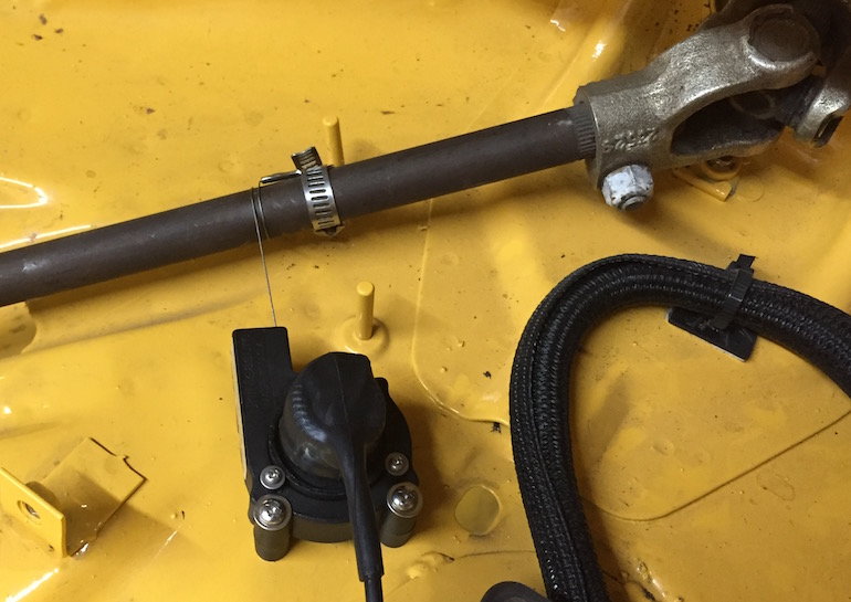
My AiM MXL2 dash install is almost complete and all has gone amazingly well and has been much easier than I expected. One of the last steps was to install, setup, and calibrate the string pot steering angle sensor. Here is a photo of the install:
Unlike most of the sensors on my car, the string pot steering angle sensor requires calibration and there are at least a couple of different ways to do this. I will describe the two I tried and I will say now that I think the second method is the best by a good margin. Note the "steps" in these methods are not "step by step" instructions. Any specific details left out should be easy to fill in. If not, just ask and I will provide more detail.
First Method:
Go to the "Channels" tab and open the channel to which the string pot steering angle sensor is connected. Set the "Function" to "Angle", the "Sensor" to "Angular Pot. Caleb", "Unit of Measure" to "deg", "Total Potentiometer Travel to "360" degrees, and then save it.
Now, with your laptop connected to your dash, go to "Connected Devices" and select your dash. Then, in "Live Measures" click on "Calibrate" and select the steering angle sensor. There you will see that you calibrate the sensor using two positions.
Second Method:
This is a two part method. First, go to the "Channels" tab and open the channel to which the string pot steering angle sensor is connected. Set the "Function" to "Voltage", the "Sensor" to "Generic 0-5 V", "Unit of Measure" to "mV", and then save it. Connect to the dash and transmit the setup to the dash. Then, go to "Connected Devices" and select your dash. Select the "Live Measures" tab. You will see the channel that has the steering wheel sensor attaches has some value in mV. Sit in the car while being able to see the computer screen and have a pen an paper handy. Center the wheel with the from wheels facing straight ahead. Write down the mV value for 0 degrees. Turn the wheel 180 degrees to the left and write down the mV value for -180 degrees. Turn back to 90 degrees to the left and write down the mV value for -90 degrees. Turn the wheel back to 0 degrees. Now turn the wheel 180 degrees to the right and write down the mV value for +180 degrees. Turn back to 90 degrees to the right and write down the mV value for +90 degrees.
Now create a custom angle sensor with the 5 values you just took. I started with -180, then -90, 0, +90, and finally +180. You should end up with a relatively linear line. Now change your setup to use the new custom sensor and transmit it to the dash.
The second method is certainly more complicated but it provided me with significantly better results. Using the first method, I could never get reasonable results at all 5 positions (0, -90, -180, +90, and +180). Using the second method, I did. Even -45 and +45 degrees looked right which was not the case with the first method.
Of course, I would expect to get better results when using 5 points of data versus 2.
Anyway, I thought I would pass this on in case it might help someone else setup their string pot steering sensor.
Interesting. There are many types of sensors, too. String pot, clogged belt and linear pot. All have sufficient resolution to be highly accurate and repeatable, providing the installation is correct.
I've sold or installed myself over ninety steering angle sensors, and never felt the need or realized a benefit from using other than the standard calibration, as opposed to the making of a custom sensor.
Interested more in steered angle, rather than steering angle, so that could come into it.
Thanks for posting. That's the delight in all this, there are many ways to skin a ��
__________________ -Peter Krause www.peterkrause.net www.gofasternow.com
"Combining the Art and Science of Driving Fast!"
Specializing in Professional, Private Driver Performance Evaluation and Optimization
Consultation Available Remotely and at VIRginia International Raceway
I've sold or installed myself over ninety steering angle sensors, and never felt the need or realized a benefit from using other than the standard calibration, as opposed to the making of a custom sensor.
Interested more in steered angle, rather than steering angle, so that could come into it.
The standard calibration method (the first method in my post) does not offer many data points (2) and to me, that seems a bit strange. If you look at the photo of my install, where I have attached the string is pretty good. The shaft is perfectly round. The string does not wrap onto itself. All in all, the string should be very consistent.
Maybe steering wheel angle accuracy is not all that important as long as you get the wheel angles accurate. I haven't looked at the math channel formulas closely enough to know. But, the engineer in me wants to get the steering wheel angles accurate too and the second method is much better than the first for that in my install.
Scott, I still don't see why your five-point sensor setup is better than knowing the linear values established when you know the two end points, in this application.
The only reason to set up a custom sensor (to me) is if a sensor calibration curve doesn't exist OR the sensor values between full deflection or range of measures are NOT linear.
As I described in my first post, using just 2 data points results in inaccurate results. I tried -180 and +180. But at 0 degrees my steering wheel was clearly not centered. I tried -90 and +90. I tried 0 and +180. Doing this always resulted with some positions not being correct. Clearly something is not linear.
Scott, Peter is correct regarding the steering calibration routine should work well by using 2 points on what most of the time is a simple linear relationship. Seems you are getting different results and I will test later today.
This response is more focused on helping you with a shortcut to accomplishing your task of getting mV of the sensor at different points for your Custom Sensor. When you are in RS3 and in the 'Live Measures' screen, simply click on the 'mV Values' button near the top of the screen and the software will show you the raw mV values. No need for you to change your configuration to have the sensors show voltage, you can get the same values at the Live Measures page.
I've never done it with a custom sensor, so I don't have a comparison. The picture is not coming across , so I can't see the setup, but it should be linear if it's just wrapping around the steering column. There is no reason it shouldn't be.
What is the delta from your high to low mV reading?
I fixed the install photo problem with my first post.
I am at a loss. I tried setting up the sensor again using the first method and both 90 degree positions are clearly not right sitting in the car. You can see from the mV values I listed in post #5 that the 0 and 180 degree spots make perfect sense. But the 90 degree values would seem to be off yet are correct in the car.
Umm, no. 360 degrees at the wheel should be 360 degrees at the steering box/rack.
Umm, yes! The cardan joint (u-joint) is not a constant velocity joint. It slows down and speeds up the shaft during the rotation. So, while there is 360 degrees of rotation on one side of the joint and 360 degrees of rotation on the other, there is variation in linearity in between. This would explain what I am seeing. What I need to do is put the sensor on the steering column directly and not on a rod past the cardan joint.
Wait a second, aren't u-joints nonlinear by nature and the greater the angle the more non-linear they become?
Originally Posted by ProCoach
Umm, no. 360 degrees at the wheel should be 360 degrees at the steering box/rack.
I've never looked to see if they are linear throughout the travel. At 0 and 360 degrees they are equal, but I'm not sure if they are linear through the rotation. I assume the are, but there is a saying about that.
Also, you're measurement on a 10" string is pretty small.
I looked at my 911 steering setup and there is no easy way to get to the steering column directly. The shaft after the second cardan joint will turn with the same linearity as the shaft the steering wheel is attached to. So, if I move the sensor and set it up to measure that shaft's rotation, I should get the linear values desired.
 10-02-2016, 05:37 AM