S2 Supercharger Build Thread UPDATE 22 Feb 2012 - DYNO PLOTS
 11-19-2011, 06:12 AM
#1
Three Wheelin'
Thread Starter
So after a year of planning, thinking and procuring it is now time to start construction of my S2 supercharger system. My reasons for this project is an aim to move the car's performance up to where I can compete with GT3s for club sprints. I'll end up this year as a class E winner (7.5 to 8.5 kg/kw P/w) so I'm looking for another challenge next year - moving into class C (5.5 - 6.5 kg/kw). For the small cost associated with upgrading the S2, I think I can be competitive against cars in class C and also those GT3's in the classes above. I know I won't be able to beat the better GT3 drivers, but I'm sure it will be fun nonetheless.
The kit will be a Rotrex C30-94 running about 6-7 psi and utilising a 951 intercooler. Interestingly for some, I will be keeping the AFM in the first instance and perhaps later upgrading to a MAF depending on how the AFM fares. Other parts of the system includes 951 injectors, and a retune using an Ostrich II emulator, fast response IAT, MAP sensor and LM-2 for logging.
Anyway, preparation work is continuing and I have sorted out a few of the things necessary.
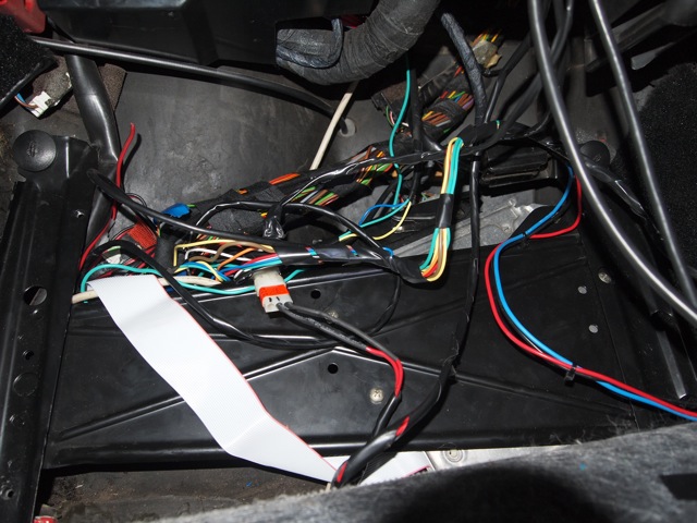
The first thing to do was to wire in the LM-2 analogue inputs into the DME harness. This is not such a fun thing to do having to use a certain amount of acrobatics to work in the passenger footwell to get to all the wires.
DME wiring splice. Note I have also connected wires to both the variant and coding plugs to allow remote switching of maps.
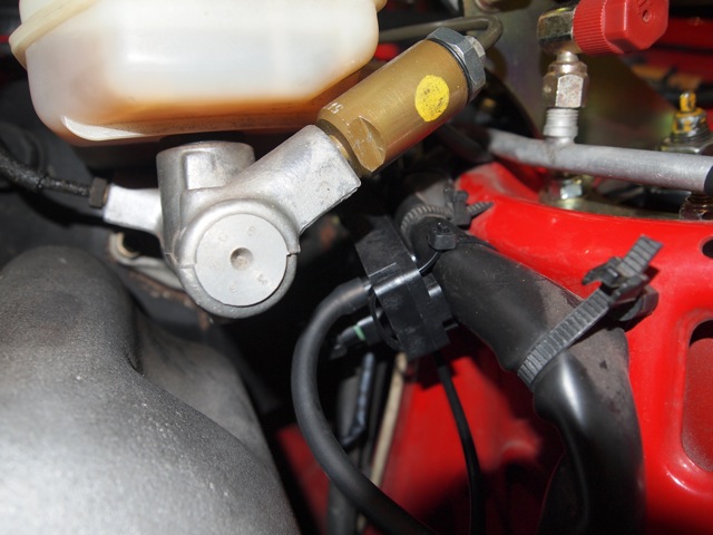
2 bar Delphi MAP sensor installed to intake manifold vacuum line and connected to LM-2 inputs.
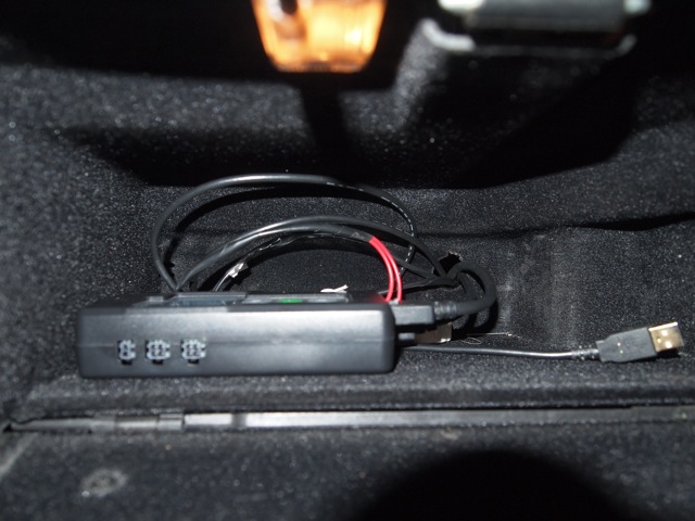
LM-2 sits in the glovebox, all wires are routed through that convenient hole that Porsche put in the back of the glovebox.
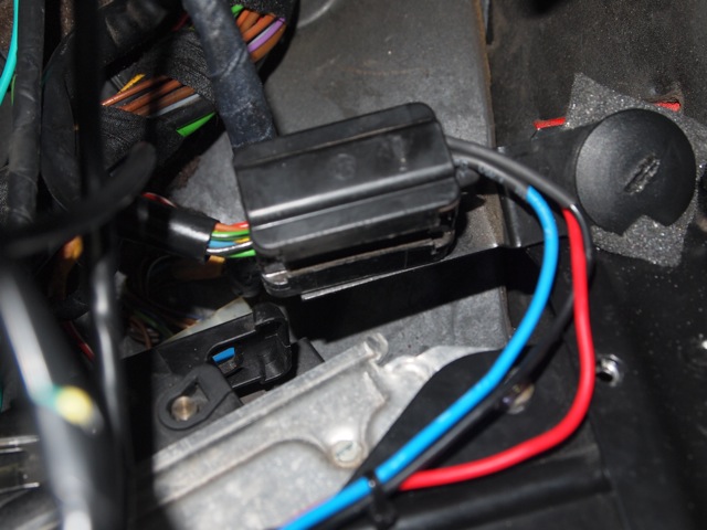
Wiring for knock sensor has been connected to the diagnostic plug in the passenger footwell.
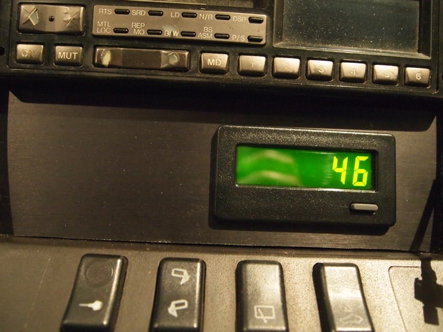
Rather than go to the hassle of getting a custom faceplate done, why not make your own? I made this from a faceplate used in equipment racks. It is anodised aluminium (we can't buy aluminum here ). The hole was simply cut using a jigsaw and the panel is held in with some double sided foam tape). The left side will eventually house a SPA design dual boost/oil temp digitial gauge. The knock counter is a Redlion CUB400 counter with a nice backlight powered on when the engine is switched (powered by diagniostic plug).
A made up a wiring table for the connections - may be of use to someone:
DME Terminal Assignment2.pdf
The kit will be a Rotrex C30-94 running about 6-7 psi and utilising a 951 intercooler. Interestingly for some, I will be keeping the AFM in the first instance and perhaps later upgrading to a MAF depending on how the AFM fares. Other parts of the system includes 951 injectors, and a retune using an Ostrich II emulator, fast response IAT, MAP sensor and LM-2 for logging.
Anyway, preparation work is continuing and I have sorted out a few of the things necessary.
The first thing to do was to wire in the LM-2 analogue inputs into the DME harness. This is not such a fun thing to do having to use a certain amount of acrobatics to work in the passenger footwell to get to all the wires.
DME wiring splice. Note I have also connected wires to both the variant and coding plugs to allow remote switching of maps.
2 bar Delphi MAP sensor installed to intake manifold vacuum line and connected to LM-2 inputs.
LM-2 sits in the glovebox, all wires are routed through that convenient hole that Porsche put in the back of the glovebox.
Wiring for knock sensor has been connected to the diagnostic plug in the passenger footwell.
Rather than go to the hassle of getting a custom faceplate done, why not make your own? I made this from a faceplate used in equipment racks. It is anodised aluminium (we can't buy aluminum here
). The hole was simply cut using a jigsaw and the panel is held in with some double sided foam tape). The left side will eventually house a SPA design dual boost/oil temp digitial gauge. The knock counter is a Redlion CUB400 counter with a nice backlight powered on when the engine is switched (powered by diagniostic plug).A made up a wiring table for the connections - may be of use to someone:
DME Terminal Assignment2.pdf
Last edited by Eric_Oz_S2; 05-07-2012 at 07:02 AM.
 11-19-2011, 06:25 AM
#2
Three Wheelin'
Thread Starter
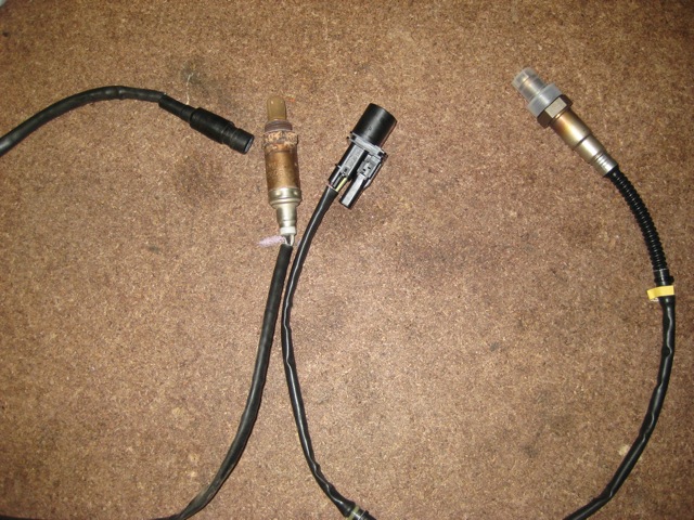
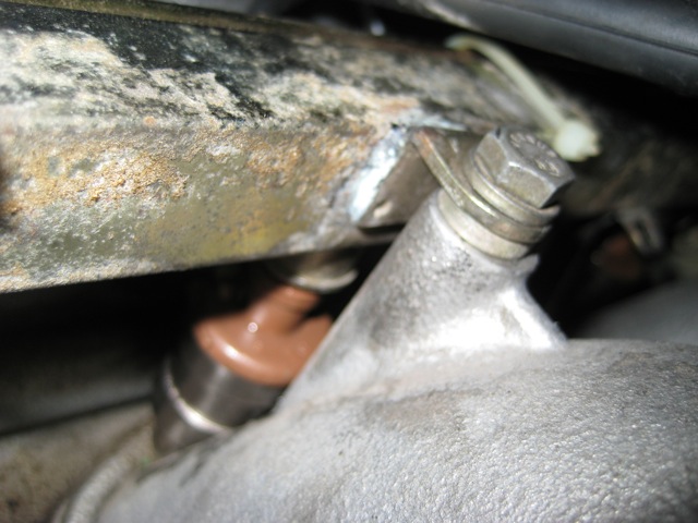
Next up is the install of the WBO2 sensor. I will be using the LM-2 's NBO2 simulation for tuning, so I can use the stock bung.
The WBO2 is interchangeable with the stock NBO2 thread.
WBO2 installed.
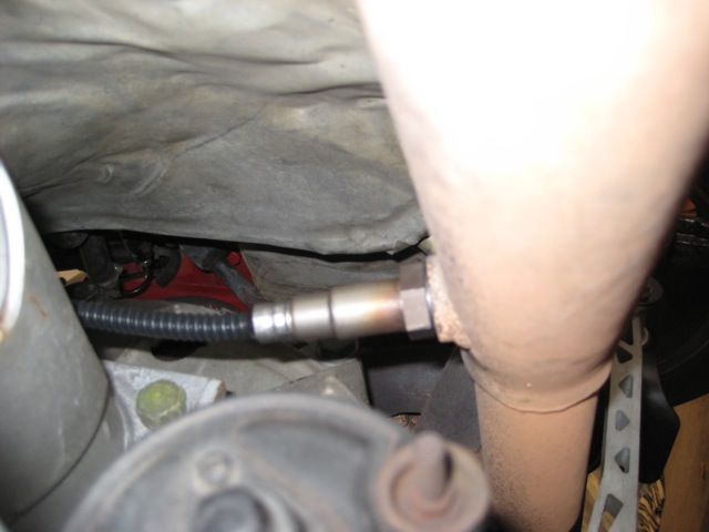
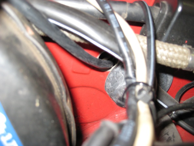
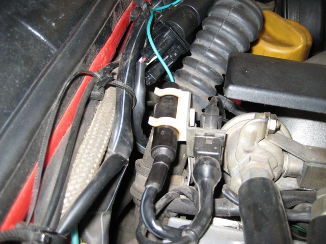
There is a convenient hole covered with a grommet that is next to the main harness penetration through the firewall. It is perfect for use for feeding the WBO2 lead through to the passenger compartment and certainly a lot simpler than the sometimes used shifter hole solution.
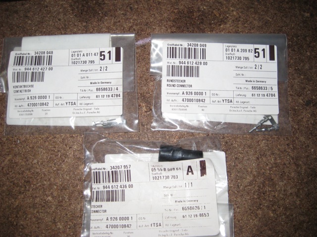
Some special order parts from Porsche Germany - in this case the 3 pin round plug and pins for connecting the LM-2 NBO2 output back into the DME harness. Effectively I am plugging the LM-2 output into where the NBO2 sensor normally connects - very neat.
Here is the plug assembled. I haven't connected the heater outputs to anything as it doesn't seem to matter if these are left disconnected. I have sean some in the 964 forum where load resistors are connected to the power feed to prevent errors being generated by the DME.
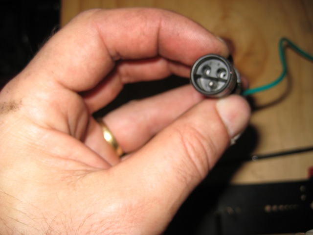
This thing was a bugger to get together, the plug is rubber and the wire and pin must be pushed through from the back quite a way. A small screw driver and some force were in order.
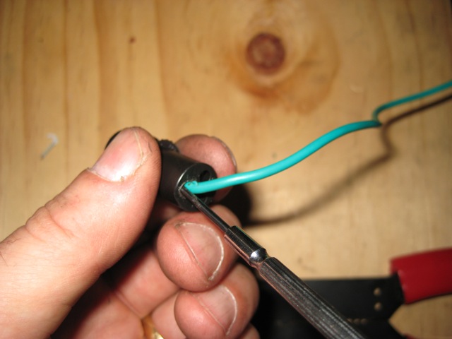
All wired up. The green wire is the output from the LM-2.
The WBO2 is interchangeable with the stock NBO2 thread.
WBO2 installed.
There is a convenient hole covered with a grommet that is next to the main harness penetration through the firewall. It is perfect for use for feeding the WBO2 lead through to the passenger compartment and certainly a lot simpler than the sometimes used shifter hole solution.
Some special order parts from Porsche Germany - in this case the 3 pin round plug and pins for connecting the LM-2 NBO2 output back into the DME harness. Effectively I am plugging the LM-2 output into where the NBO2 sensor normally connects - very neat.
Here is the plug assembled. I haven't connected the heater outputs to anything as it doesn't seem to matter if these are left disconnected. I have sean some in the 964 forum where load resistors are connected to the power feed to prevent errors being generated by the DME.
This thing was a bugger to get together, the plug is rubber and the wire and pin must be pushed through from the back quite a way. A small screw driver and some force were in order.
All wired up. The green wire is the output from the LM-2.
11-19-2011, 06:36 AM
#3
Three Wheelin'
Thread Starter
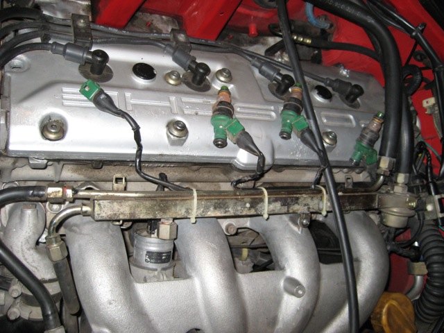
Next up is to replace the stock injectors with turbo injectors. The S2 injectors flow at 264 cc/min at 3.0 bar and the turbo injectors flow at 370 cc/min (968 injectors flow at 296 cc/min). From a calculation of the S2 injector capacity, these would need to flow at 130% for the expected boost. Some have used a RRFPR for this, but on these old injectors the spray patterns break down at higher pressure and they become inefficient. The turbo injectors have been calculated to run at 90% and should provide enough fuel with the S2 3.8 FBR and expected 300hp target output (flywheel). I actually got reconditioned Mustang SVO brown top injectors which are identical to the turbo ones.
This is one job I always hate. Removing the plug on the fuel rail (the one with the ball bearing seal) always results in a heap of fuel spill. You can't get a container under so you use paper towels and stink out the garage.
Injectors removed from fuel rail:
Old and new.
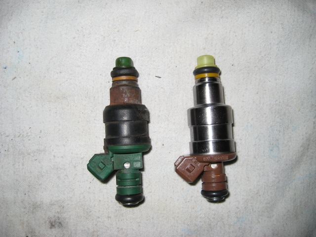
New injectors in:
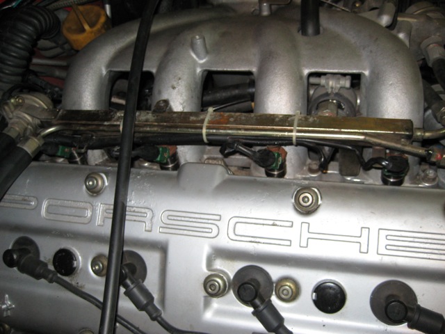
The S2 fuel rail has an unusual washer arrangement for the fuel rail connection. You need to be careful not to loose these spacer washers that sit between the rail and manifold:
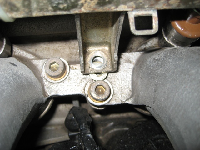
There's one on top too:
Next up is to reprogram the DME to put in a new injector factor. Basically I'm changing the stock (Position 0) of the FQS address in the DME and reducing this value to compensate for the larger flows. Hopefully my estimated value will be OK.
This is one job I always hate. Removing the plug on the fuel rail (the one with the ball bearing seal) always results in a heap of fuel spill. You can't get a container under so you use paper towels and stink out the garage.
Injectors removed from fuel rail:
Old and new.
New injectors in:
The S2 fuel rail has an unusual washer arrangement for the fuel rail connection. You need to be careful not to loose these spacer washers that sit between the rail and manifold:
There's one on top too:
Next up is to reprogram the DME to put in a new injector factor. Basically I'm changing the stock (Position 0) of the FQS address in the DME and reducing this value to compensate for the larger flows. Hopefully my estimated value will be OK.
11-19-2011, 09:05 AM
#4
Three Wheelin'
Thread Starter
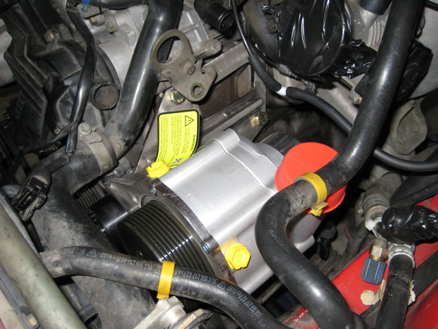
Thought I'd post a picture of the SC unit that is going in soon. Currently fitted with a 100mm pulley for initial tuning. Probably go smaller depending on boost levels achieved.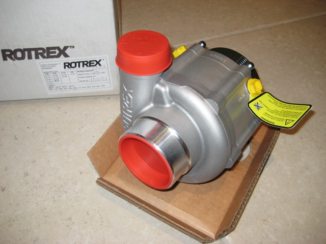
11-19-2011, 11:49 PM
#5
Three Wheelin'
Thread Starter
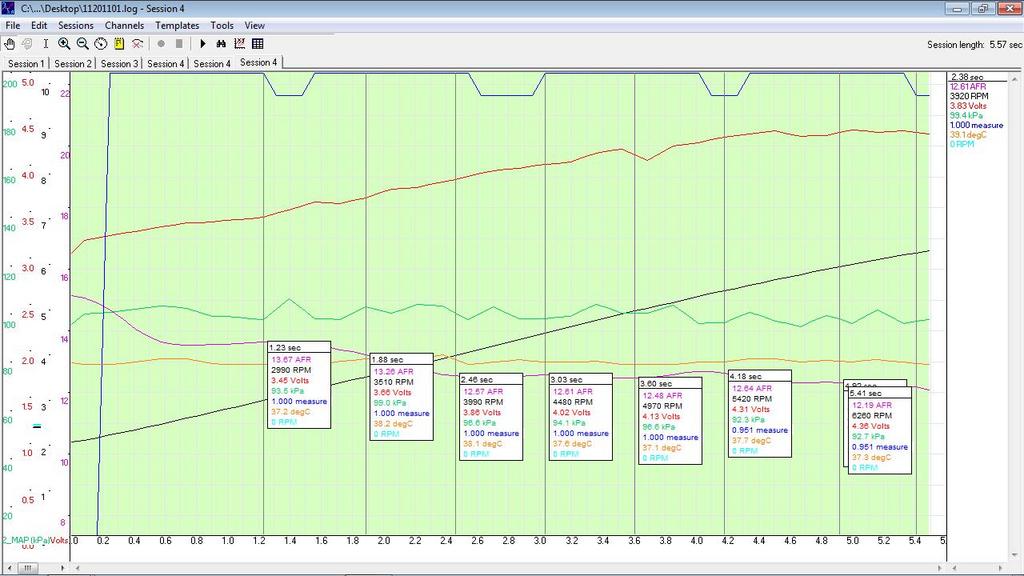
A bit of tuning today. First I logged the stock injectors so I had a baseline. AFRs are 13.9 at 3000, 13.5 at 2500, 12.7 to 5000, 12.4 to 5500, 12.3 to 6300.
Next was using the Ostrich to alter the FQS setting. Surprisingly, the required factor was only 0.9, or about -10%. Not sure why the scale factor is not proportional to the specified injector flows which would be about 0.72. I hope I can get enough fuel out of these suckers.
Here is a plot at WOT with the 0.90 scaling.
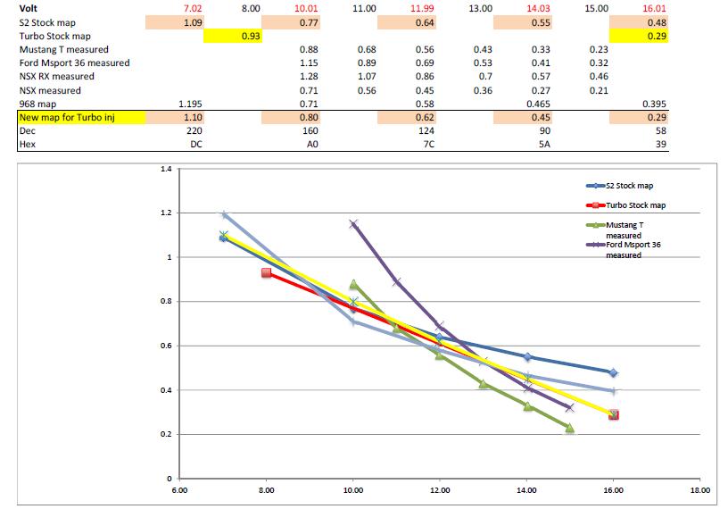
This ran a little clunky at idle, so I adjusted the lag values in the Motronic maps. I found a range of values for similar injectors and turbo injectors. It is interesting that the turbo code only has 2 values, but the S2 has 5. Turbo injectors appear to have less lag. Here is the graph I used to set the lag values. The yellow line is the adopted values.
Anyone had similar experience with scaling larger injectors?
Next up is to start dismantling the airbox, remove alternator, AFM etc and install the supercharger so I can measure up the hoses etc.
Next was using the Ostrich to alter the FQS setting. Surprisingly, the required factor was only 0.9, or about -10%. Not sure why the scale factor is not proportional to the specified injector flows which would be about 0.72. I hope I can get enough fuel out of these suckers.
Here is a plot at WOT with the 0.90 scaling.
This ran a little clunky at idle, so I adjusted the lag values in the Motronic maps. I found a range of values for similar injectors and turbo injectors. It is interesting that the turbo code only has 2 values, but the S2 has 5. Turbo injectors appear to have less lag. Here is the graph I used to set the lag values. The yellow line is the adopted values.
Anyone had similar experience with scaling larger injectors?
Next up is to start dismantling the airbox, remove alternator, AFM etc and install the supercharger so I can measure up the hoses etc.
11-20-2011, 02:55 AM
#7
Three Wheelin'
Thread Starter
Thanks Mike.
I'll be routing the inlet from behind the left headlight. Plan to run the SC inlet under to the AFM and then 90 degrees upwards through where the receiver dryer for the now removed a/c sits. The cone filter should j-u-s-t fit between the coolant tank, headlight and sc outlet pipe.
I'll be routing the inlet from behind the left headlight. Plan to run the SC inlet under to the AFM and then 90 degrees upwards through where the receiver dryer for the now removed a/c sits. The cone filter should j-u-s-t fit between the coolant tank, headlight and sc outlet pipe.
Trending Topics
11-23-2011, 12:04 AM
#9
Three Wheelin'
Thread Starter
More tuning reveals that the S2 DME is a little more complex than the older ML3.1. WOT fuel maps have adaptation applied to them, that is depending on the trim values set by closed loop at part throttle, the WOT fuel maps are scaled by these same trim values. This is evidenced by being able to get the same WOT AFRs using 0.9FQS and trimmed AFRs and then disconnecting power to the DME, setting the FQS at 0.8x (running open loop) and getting the same AFR values. Reconnect O2 and let it adapt, and AFRs have stablised. On earlier runs, setting the FQS to 0.8x resulted in leaner AFR values.
11-27-2011, 04:41 AM
#10
Three Wheelin'
Thread Starter
Progress update.
This weekend I started removing all of the bits that need to come off for the SC install.
Removed header panel, alternator and bracket, left side wheel well liner, batwing, AFM, airbox, alternator cooling duct, receiver dryer, ac pipes etc.
I also worked out where to install the oil cooler - it will go in the left hand side behind the fog light area. This will be a mirror image of the S2 oil cooler location on the right side. The two tone horns need to be swivelled out of the way so they sit further forward so they can clear the oil cooler and pipes.
I also installed the intercooler and air duct. Luckily the S2 has four of the little rubber intercooler mounting feet already provided, 3 are used to support the airbox and one supports the AFM intake pipe. Simple matter of reusing the AFM one for the intercooler support. Very handy that Porsche used the same part so you don't need to buy these. It is interesting that I needed to wind up the rear support feet and put spacers between them and the bracket/support. Without these the intercooler pipe will hit the headlight linkage bar. Not sure how the turbo gets this to work?
I also installed the Rotrex and bracket so I can now measure up all the pipework. Some dremelling was required so the bracket cleared the plastic belt covers. Very minor clash here. Here are some pics of where I am at:
Intercooler in:
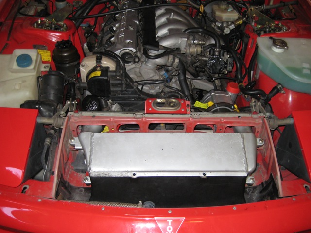
Rotrex in:
This weekend I started removing all of the bits that need to come off for the SC install.
Removed header panel, alternator and bracket, left side wheel well liner, batwing, AFM, airbox, alternator cooling duct, receiver dryer, ac pipes etc.
I also worked out where to install the oil cooler - it will go in the left hand side behind the fog light area. This will be a mirror image of the S2 oil cooler location on the right side. The two tone horns need to be swivelled out of the way so they sit further forward so they can clear the oil cooler and pipes.
I also installed the intercooler and air duct. Luckily the S2 has four of the little rubber intercooler mounting feet already provided, 3 are used to support the airbox and one supports the AFM intake pipe. Simple matter of reusing the AFM one for the intercooler support. Very handy that Porsche used the same part so you don't need to buy these. It is interesting that I needed to wind up the rear support feet and put spacers between them and the bracket/support. Without these the intercooler pipe will hit the headlight linkage bar. Not sure how the turbo gets this to work?
I also installed the Rotrex and bracket so I can now measure up all the pipework. Some dremelling was required so the bracket cleared the plastic belt covers. Very minor clash here. Here are some pics of where I am at:
Intercooler in:
Rotrex in:
11-27-2011, 07:31 PM
#12
3rd Gear
Join Date: Jan 2010
Location: Bordeaux - France
Posts: 3
Likes: 0
Received 0 Likes
on
0 Posts
Congratulation Eric, i follow your posts for a long time, i want to sc my S2 too, and it's great to see that you do it....
Just a question, where did you buy the rotrex bracket ? Thanks, cant wait to see what happen !
K�vin

Just a question, where did you buy the rotrex bracket ? Thanks, cant wait to see what happen !
K�vin
11-27-2011, 09:17 PM
#13
Three Wheelin'
Thread Starter
There are two suppliers. I got mine from Clubsport nl (in Holland). You can also get it from CustomConcepts nl. It has been a long journey (and in some ways is still only beginning). I'm willing to share all the details of the installation and tuning I do myself as I progress so hopefully it will make it easier for others to undertake a similar installation.
11-28-2011, 10:06 PM
#15
3rd Gear
Join Date: Jan 2010
Location: Bordeaux - France
Posts: 3
Likes: 0
Received 0 Likes
on
0 Posts
Thanks a lot Eric for the information.
I've installed a Split Second MAF on mine, with a Large Band lambda sensor and zt-2 zeitronix. I think it's a good way to begin the sc modification, but your solution is cheaper and works great too. If you're interested by the MAF wiring on the future, do not hesitate to ask...
Sadly, i can't start the sc installation now, my engine is on work, but i follow you with interest!